
Related Manuals for Advantech TPC-71W Series


Summary of Contents for Advantech TPC-71W Series
- Page 1 User Manual TPC-71W Series 電腦 ® ® 7" ARM Cortex -A9 Touch Panel Computer 製造商 : 研華股份有限公司 地址 : 台北市內湖區瑞光路 26 巷 20 弄 1 號 電話 :02-27927818...
- Page 2 Note 2. “○” indicates that the content of the restricted substance does not exceed the defined concentration limit. 備考 3.“ - ” 係指該項限用物質為排除項目。 Note 3. “-” indicates that the restricted substance is not present in the product. TPC-71W Series User Manual...
- Page 3 No part of this manual may be reproduced, copied, translated or transmitted in any form or by any means without the prior written permission of Advantech Co., Ltd. Information provided in this manual is intended to be accurate and reliable. How- ever, Advantech Co., Ltd.
- Page 4 Because of Advantech’s high quality-control standards and rigorous testing, most of our customers never need to use our repair service. If an Advantech product is defec- tive, it will be repaired or replaced at no charge during the warranty period. For out- of-warranty repairs, you will be billed according to the cost of replacement materials, service time and freight.
- Page 5 This product has passed the CE test for environmental specifications when shielded cables are used for external wiring. We recommend the use of shielded cables. This type of cable is available from Advantech. Please contact your local supplier for ordering information.
- Page 6 This equipment is not suitable for use in locations where children are likely to be present. Caution! Danger d'explosion si la batterie est mal remplace. Remplacer unique- ment par le meme type ou equivalent recommandé par le fabricant. Jeter les piles usagées selon les instructions du fabricant. TPC-71W Series User Manual...
- Page 7 設備有明顯的外觀破損。 請不要把設備保存在超出我們建議的溫度範圍的環境,即不要低於 -20°C (-4 °F)或高於 60°C (140°F) ,否則可能會損壞設備。 注意:如果電池放置不正確,將有爆炸的危險。因此,只可以使用製造商推薦的 同一種或者同等型號的電池進行替換。請按照製造商的指示處理舊電池。 根據 IEC 704-1:1982 的規定,操作員所在位置的音量不可高於 70dB(A)。 限制區域:請勿將設備安裝於限制區域使用。 免責聲明:該安全指示符合 IEC 704-1 的要求。研華公司對其內容的準確性不承 擔任何法律責任。 使用過度恐傷害視力。 使用 30 分鐘請休息 10 分鐘。 未滿 2 歲幼兒不看螢幕,2 歲以上每天看螢幕不要超過 1 小時。 本產品為國內裝置使用時,其電源僅限使用架構電源模組所提供電源直流輸入, 不得使用交流電源及附加其他電源轉換裝置提供電源這者,其電源輸入電壓及電 流請依說明書規定使用。 TPC-71W Series User Manual...
- Page 8 Der arbeitsplatzbezogene Schalldruckpegel nach DIN 45 635 Teil 1000 beträgt 70dB(A) oder weiger. Haftungsausschluss: Die Bedienungsanleitungen wurden entsprechend der IEC-704-1 erstellt. Advantech lehnt jegliche Verantwortung für die Richtigkeit der in die- sem Zusammenhang getätigten Aussagen ab. TPC-71W Series User Manual...
- Page 9 Don't touch any components on the CPU card or other cards while the PC is on. Disconnect power before making any configuration changes. The sudden rush of power as you connect a jumper or install a card may damage sensitive elec- tronic components. TPC-71W Series User Manual...
- Page 10 TPC-71W Series User Manual...
-
Page 11: Table Of Contents
Time And Date Setting ................16 CAN Setting .................... 16 Watchdog Setting..................17 Brightness Setting ................... 18 X11vnc Setting ..................18 Appendix A Pin Assignments .......21 MINI PCI Express Slot ................22 4-pin USB Connector ................23 COM Port ....................23 TPC-71W Series User Manual... - Page 12 TPC-71W Series User Manual...
-
Page 13: Chapter 1 General Information
Chapter General Information... -
Page 14: Introduction
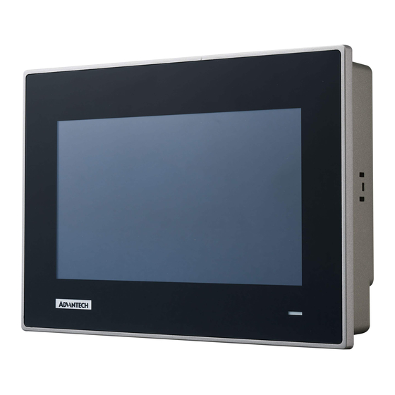
Introduction The TPC-71W series of touch panel computers consist of state-of-the-art 7” operator interface combined with ARM-based computing platform offers these key features: NXP® ARM Cortex®-A9 i.MX6 Dual/Quad core processor 7" 16:9 WSVGA LCD wide screen with PCAP multi-touch ... -
Page 15: Touchscreen
This product is intended to be supplied by IEC/UL 60950-1 and/or IEC/UL 62368-1 Listed adapter complies with Limited Power Source and rated from : 24 Vdc, mini- mum 0.6A, minimum operating temperature 50°C. 1.2.8 External I/O The arrangement of I/O ports is shown below TPC-71W Series User Manual... -
Page 16: Mounting
Le capot arrière du TPC-71 dispose de quatre trous de montage VESA (75 x 75 mm). Le kit de montage VESA doit être installé à l’aide de 4 vis M4x10L et de 4 vis M4x8L. Veuillez utiliser un appareil de montage approprié pour éviter tout risque de blessure. TPC-71W Series User Manual... - Page 17 (Torque: 2 kgf-cm) These screws will push the mounting panel and secure the unit. Accrocher la pince dans les trous et serrer les vis (couple: 2 kgf-cm) Ces vis vont pousser le panneau de montage et sécuriser l'unité. TPC-71W Series User Manual...
-
Page 18: Dimensions And Cutout
Dimensions and Cutout Cutout Dimension:192 x 138.5(7.56 x5.45inch) TPC-71W Series User Manual... -
Page 19: Chapter 2 System Setup
Chapter System Setup... -
Page 20: Transport And Unpacking
Configuration can be set via the switch on the TPC-71W rear board as shown below. The default setting is RS232 mode and eMMC Boot. Kindly refer to the following pin definition table for mode switch. TPC-71W Series User Manual... - Page 21 Bit 2,4,5,6 ON Bit 1,3,7,8 OFF CAN Mode termination Bit 1,2,3,4 OFF resistor Boot Mode: eMMC/SD Card SD boot the sys- Bit 2 ON Bit 1 OFF eMMC boot the Bit 1 ON system Bit 2 OFF TPC-71W Series User Manual...
-
Page 22: Mini Pci Express Module Installation
TPC-71W provides additional 1 internal 4-pin USB connector and allows users to expend the function like NFC or the other USB type modules. Please open the rear bracket and configure the USB module by USB connector. (Refer to Appendix B for the detailed USB connector pin assignments) TPC-71W Series User Manual... -
Page 23: System Power On
24 Vdc, minimum 0.6A, with minimum operating temperature 50°C, and has to be evaluated according to IEC/UL 60950-1 and/or IEC/UL 62368-1. Warning! The system may get damaged when the power is turned on and the power source is not connected to the correct pins. TPC-71W Series User Manual... - Page 24 TPC-71W Series User Manual...
-
Page 25: Chapter 3 Linux Ubuntu
Chapter Linux Ubuntu... -
Page 26: Arm Ubuntu16.04
Get New Software Package List: # sudo apt-get update Upgrade Software If There Is Updated Version Software Available: # sudo apt-get upgrade Search Needed Software Package: #apt-cache search packagename List More Command and Option: # apt-get help TPC-71W Series User Manual... -
Page 27: Tpc-71W Module Extension
This chapter will take mPCIe Wi-Fi module as an example to demon- strate how to use a mPCIe module on TPC-71W 3.3.1 Module Information Advantech WiFi Module Part Number?EWM-W151H01E 3.3.2 The Configuration and Connection of WIFI Module Configure by User Interface Setp1: Open terminal and load Wi-Fi module document #insmod /lib/modules/4.1.15/kernel/drivers/net/wireless/88x2bu.ko... -
Page 28: Time And Date Setting
Link encap:UNSPEC HWaddr 00-00-00-00-00-00-00-00-00-00-00-00-00-00-00-00 UP RUNNING NOARP MTU:16 Metric:1 RX packets:0 errors:0 dropped:0 overruns:0 frame:0 TX packets:0 errors:0 dropped:0 overruns:0 carrier:0 collisions:0 txqueuelen:10 RX bytes:0 (0.0 B) TX bytes:0 (0.0 B) Interrupt:31 TPC-71W Series User Manual... -
Page 29: Watchdog Setting
WDT start. WDT timeout has been set to 20 seconds. After that, WDT will reset CPU. WDT keep alive. WDT keep alive..Disable wdt: root@tpc71wn10pa:~# cd /usr/Advantech/EAPI_test root@tpc71wn10pa:/usr/Advantech/EAPI_test# ./testdl_wdt -d MaxDelay:0 MaxEventTimeout:0 MaxResetTimeout:6553 WDT stop. TPC-71W Series User Manual... -
Page 30: Brightness Setting
Current bright: 4 Current bright: 4 Current bright: 5 Current bright: 5 Current bright: 6 Current bright: 6 Current bright: 7 Current bright: 7 X11vnc Setting Step 1: login with debug console Step 2: get current ethernet IP TPC-71W Series User Manual... - Page 31 Step 3: start x11vnc server Step 4: Remote desktop (use VNC Viewer 6.18.625) TPC-71W Series User Manual...
- Page 32 TPC-71W Series User Manual...
-
Page 33: Appendix A Pin Assignments
Appendix Pin Assignments... -
Page 34: Mini Pci Express Slot
PCI1.1 was +3.3V, WAKE# Open Drain active Low sig- +3.3V PCI1.2 was +3.3Vaux nal. This signal is used to request that the system return from a sleep/sus- pended state to service a function initiated wake event. TPC-71W Series User Manual... -
Page 35: 4-Pin Usb Connector
1.25 mm 4-pin USB connector Signal Description USB VBUS USB Power output ,USB2.0 5V/0.5A USB_P- USB2.0 date - USB_P+ USB2.0 date + Ground for Power return COM Port 9-Pin Com Port Connector RS232 RS485 TPC-71W Series User Manual... - Page 36 No part of this publication may be reproduced in any form or by any means, electronic, photocopying, recording or otherwise, without prior written permis- sion of the publisher. All brand and product names are trademarks or registered trademarks of their respective companies. © Advantech Co., Ltd. 2019...
Need help?
Do you have a question about the TPC-71W Series and is the answer not in the manual?
Questions and answers