Advertisement
Quick Links
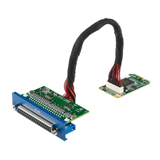
MOS-1120Y-0201E Isolated RS-232 iDoor Module,
MOS-1120Y-1401E Non-Isolated RS-232 iDoor Module,
MOS-1121Y-0201E Isolated RS-422/485 iDoor Module,
MOS-1121Y-1401E Non-Isolated RS-422/485 iDoor Module
User Manual
MOS-1120Y/MOS-1121Y is serie of industrial Serial Communication Module.
P/N
MOS-1120Y-0201E
MOS-1121Y-0201E
MOS-1120Y-1401E
MOS-1121Y-1401E
This manual gives you inspection and installation of hardware and drivers.
1. Packing List
MOS-1120/MOS-1121
miniPCIe Card x 1
DB37 I/O Plate x 1 with iDoor bracket x 1
Wire cable x 1
Startup Manual x 1
DB37 to DB9(4 ports) cable (MOS-1121Y-1401E only)
Note: If any of these items are missing or damaged, please contact your distributor or sales representative immediately.
2. Initial Inspection
MOS-1120/MOS-1121 was carefully inspected mechanically and electrically before it was shipped. It should be
free of marks and scratches and in perfect working order when received.
As you unpack the MOS Module, check for signs of shipping damage (damaged box, scratches, dents, etc.). If it is
damaged or it fails to meet specifications, notify our service department or your local sales representative immediately. Also
notify the carrier. Retain the shipping carton and packing material for inspection by the carrier.
After inspection we will make arrangements to repair or replace the unit. When you handle the MOS Module, remove
it from its protective packaging by grasping the rear metal panel. Keep the anti-vibration packing. Whenever you remove
the card from the PC, store it in this package for protection.
Description
Isolated RS-232, 2-Ch, DB9, PCIe I/F
Isolated RS-422/485, 2-Ch, DB9, PCIe I/F
Non-Isolated RS-232, DB37, 4-Ch, PCIe I/F
Non-Isolated RS-422/485, DB37, 4-Ch, PCIe I/F
MOS-1120/MOS-1121 User Manual 1
Advertisement

Related Manuals for Advantech MOS-1120Y-0201E


Summary of Contents for Advantech MOS-1120Y-0201E
- Page 1 MOS-1120Y-0201E Isolated RS-232 iDoor Module, MOS-1120Y-1401E Non-Isolated RS-232 iDoor Module, MOS-1121Y-0201E Isolated RS-422/485 iDoor Module, MOS-1121Y-1401E Non-Isolated RS-422/485 iDoor Module User Manual MOS-1120Y/MOS-1121Y is serie of industrial Serial Communication Module. Description MOS-1120Y-0201E Isolated RS-232, 2-Ch, DB9, PCIe I/F MOS-1121Y-0201E Isolated RS-422/485, 2-Ch, DB9, PCIe I/F...
- Page 2 Avoid touching the exposed circuit connectors. We also recommend that you use a grounded wrist strap and place the card on a static dissipative mat whenever you work with it. Advantech provides WDM CAN driver that allows you to configure your hardware and store the settings in your Windows 3. Driver Setup & Installation registry.
-
Page 3: Pin Assignments
The following table and figure shows the pin assignments of two male DB9 connectors on the iDoor bracket for MOS-1120Y-0201E card in RS-232 Mode. Table 4.1: MOS-1120Y-0201E Male DB9 on iDoor bracket 4.2 MOS-1121Y-0201E The following table and figure shows the pin assignments of two male DB9 connectors on the iDoor bracket for MOS-1121Y-0201E card in RS-422 and RS-485 Modes. - Page 4 4.3 MOS-1120Y-1401E The following tables and figures show the pin assignments of 1 female DB37 connector one the iDoor bracket to male DB9 for MOS-1120Y-1401E card in RS-232 mode. Male DB9 on Cable Table 4.3: MOS-1120Y-1401E Table 4.4: MOS-1120Y-1401E Female DB37 on iDoor bracket 4.4 MOS-1121Y-1401E The following tables and figures show the pin assignments of 1 female DB37 connector one the iDoor bracket to male DB9 for MOS-1121Y-1401E card in RS‐422 and RS‐485 modes.
- Page 5 Table 4.5: MOS-1121Y-1401E Male DB9 on Cable Table 4.6: MOS-1121Y-1401E Female DB37 on iDoor bracket MOS-1120/MOS-1121 User Manual 5...
-
Page 6: Jumper And Switch Settings
5. Jumper and Switch Settings 5.1 MOS-1121Y-0201E Settings Table 5.1: MOS-1121Y-0201E Master/Slave Settings Table 5.2: MOS-1121Y-0201E Terminal Resistor Settings 5.2 MOS-1121Y-1401E Settings Table 5.3: MOS-1121Y-1401E Master/Slave Settings MOS-1120/MOS-1121 User Manual 6... - Page 7 Table 5.4: MOS-1121Y-1401E Terminal Resistor Settings 6. Wiring 6.1 RS-232 Signal Wiring Since the RS-232 interface is not strictly defined, many devices have their own connection methods which may ignore some signal lines or define reserved lines for other functions. It is best to refer to the user’s manual for your device for installation instructions.
- Page 8 Table 6.2: Modem Connections For DTE to DCE connections, use a straight through cable (i.e., you don't have to reverse lines 2 and 3, lines 4 and 5, and lines 6 and 20 since, in general, the DCE RS-232 interfaces are reversed themselves). Table 6.3: Terminal without Handshake Therefore, if you are not using CTS, RTS, DSR,DTR and DCD signals, short pins 4 and 5 together, and please short pins 6, 8,and 20 together.
- Page 9 6.3 RS-485 Signal Wiring The RS-485 standard supports half-duplex communication. This means that just two wires are needed to both transmit and receive data. Handshaking signals (such as RTS, Request To Send) are normally used to control the direction of the data flow and to switch the transmission accordingly. In RS-485 mode, the PCM-24D2R4/24D4R4 cards automatically sense the direction of the data flow and switch the transmission direction —...
Need help?
Do you have a question about the MOS-1120Y-0201E and is the answer not in the manual?
Questions and answers