Advertisement
Quick Links
Advertisement

Related Manuals for NXP Semiconductors S32V234-EVB2


Summary of Contents for NXP Semiconductors S32V234-EVB2
- Page 1 S32V234-EVB2 QUICK START GUIDE REV 2. FEBRUARY 2018 EXTERNAL USE...
- Page 2 Table of Contents • Board Overview • Power & Reset • Serial communications • Boot sources and boot configurations • Displays • Camera inputs EXTERNAL USE...
-
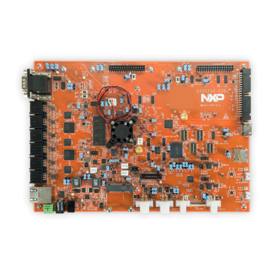
Page 3: Board Overview
Board Overview (On back) MIPI 1 (On back) MIPI 0 HDMI Auto UART1 UART0 POWER FlexRay FlexRay EXTERNAL USE LIN0/1 mPCIE... - Page 4 Power • EVB2 uses 12V barrel jack power supply, or wire-ended jack • DO NOT USE BOTH SIMULATENOUSLY OR YOU WILL LIKELY DAMAGE YOUR BOARD • 12V hot goes to Pin 1 of Barrel jack or wire-end plug. See rear of board for pin marking •...
- Page 5 Reset EVB2 provides “SOFT RESET” and • “POR RESET” buttons Pressing “POR RESET” pulls active low • “EXT_POR” signal on S32V234 chip to Pressing “SOFT RESET” pulls active low • “RESET” signal on S32V234 chip to • Refer to S32V234 Reference Manual for specifics on levels of reset and device reset flow EXTERNAL USE...
-
Page 6: Serial Communications
Serial Communications • EVB2 has an FTDI chip to convert UART signals to USB friendly format, to be connected to host PC • UART 0 (with arrow) is default serial output for Linux BSP boot images. • Default comms rate is 115200 baud with 8 data bits, 1 stop bit, no parity. - Page 7 Boot configurations The S32V234 has are three ‘Boot modes’: • Serial download: Allows external tool to use CAN or UART to download code into RAM and start execution. Code must be redownloaded on every reset in this mode. Uses 48kbps baud rate, see S32V234 reference manual, system boot chapter, for specifics.
- Page 8 Display • EVB2 has TFT display or HDMI. Jumper J36 (circled) set to 1&2 for HDMI (yellow arrow), 2&3 for LVDS (blue arrow) • NOTE: Power off board before changing any jumpers or switches. EXTERNAL USE...
-
Page 9: Camera Inputs
Camera inputs • EVB2 two MIPI camera inputs, and two VIU (parallel) inputs • NXP and distributors sell MIPI cameras designed for use with this board • Additionally can be added and 5V/12V external power can be provided (see schematics for pinout) •... -
Page 10: Camera Configurations
Camera configurations • By default, jumpers J6 & J4 should be set to 2&3 to keep optional voltage disabled. • This configuration is suitable for most MIPI cameras that do not require additional voltage supply. It is also the safest configuration when using a new camera. - Page 11 Camera configurations • Another NXP-endorsed camera module is the OV10635/10640 with MAXIM 9271 Serializer, paired with the MAXIM 9286 Deserializer (both pictured). This camera set requires the optional 12V to be enabled. • To prepare to use the MAX9271/86 Ser/Des setup, first ensure power is off and unplugged from the board.
- Page 12 RCON Table See schematics for RCON to BOOTCFG switch mapping. Note: The Linux BSP has only been validated on certain configurations. Please see the User Manual for more information on validated settings. EXTERNAL USE...
Need help?
Do you have a question about the S32V234-EVB2 and is the answer not in the manual?
Questions and answers