
Related Manuals for NXP Semiconductors S32K144 EVB


Summary of Contents for NXP Semiconductors S32K144 EVB
- Page 1 S32K144 EVB QUICK START GUIDE REV4.2 APPLIES FOR: S32K144 EVB (SCH-29248 REV B) EXTERNAL USE...
- Page 2 Contents: Get to Know S32K144 EVB • Out of the Box Setup • Out of the Box Experience (OOBE) based on the FreeMASTER tool • Introduction to OpenSDA • Creating a new S32DS project for S32K144 • S32DS Debug basics •...
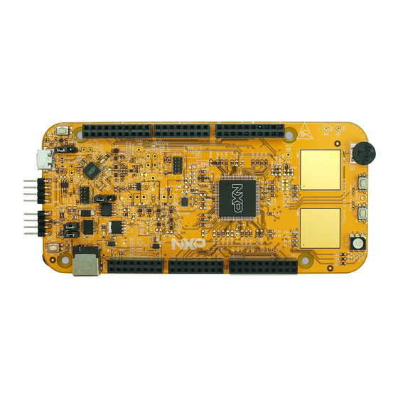
- Page 3 Get to know S32K144-EVB CAN Communication Bus LIN Communication Bus OpenSDA USB SBC UJA1169 Reset Button External Power Supply (5-12V) OpenSDA MCU OpenSDA JTAG J2 Header J3 Header J14 SWD connector J1 Header J4 Header S32K144 MCU J6 Header J5 Header Touch electrodes RGB LED Potentiometer...
- Page 4 Features: S32K144 EVB • Supports S32K144 100LQFP • Small form factor size supports up to 6” x 4” • Arduino™ UNO footprint-compatible with expansion “shield” support • Integrated open-standard serial and debug adapter (OpenSDA) with support for several industry-standard debug interfaces •...
- Page 5 Header/Pinout Mapping for S32K144 PORT FUNCTION PORT FUNCTION J2-19 PTE10/PTA3 D15/I2C_SDA J2-20 GPIO PORT FUNCTION PORT FUNCTION J2-17 PTE11/PTA2 D14/I2C_CLK J2-18 GPIO J3-02 PTB6* GPIO J3-01 J2-15 ANALOGUE REF J2-16 PTA14 GPIO J3-04 PTB7* GPIO J3-03 IOREF J2-13 J2-14 PTE7 GPIO GPIO RESET...
-
Page 6: Jumper Settings
Jumper Settings Jumper Configuration Description Reset signal to OpenSDA, use to enter into J104 OpenSDA Bootloader mode Reset signal direct to the MCU, use to reset 2-3 (Default) S32K144. J107 S32K144 powered by 12V power source. 2-3 (Default) S32K144 powered by USB micro connector. -
Page 7: Hmi Mapping
HMI mapping Component S32K144 Red LED PTD15 (FTM0 CH0) Blue LED PTD0(FTM0 CH2) Green LED PTD16(FTM0 CH1) Potentiometer PTC14 (ADC0_SE12) PTC12 PTC13 OpenSDA UART TX PTC7(LPUART1_TX) OpenSDA UART RX PTC6(LPUART1_RX) CAN TX PTE5(CAN0_TX) CAN RX PTE4 (CAN0_RX) LIN TX PTD7(LPUART2_TX) LIN RX PTD6 (LPUART2_RX) SBC_SCK... - Page 8 S32K144 EVB OUT OF THE BOX EXTERNAL USE...
- Page 9 Step 1: Power up the Board – EVB Power Supplies The S32K144-EVB evaluation board powers from a USB • or external 12V power supply. By default USB power is enabled with J107 (check slide 5) Connect the USB cable to a PC using supplied USB •...
- Page 10 Step 1: Power up the Board – Is it powered on correctly? When powered through USB, LEDs D2 and D3 should light green • Once the board is recognized, it should appear as a mass storage • device in your PC with the name EVB-S32K144. EXTERNAL USE...
- Page 11 Step 1: Power up the Board – Is it powered on correctly? Board is preloaded with a software, in • which the red, blue and green leds will toggle at different rates. EXTERNAL USE...
- Page 12 S32K144 EVB OUT OF THE BOX EXPERIENCE BASED ON THE FREEMASTER TOOL EXTERNAL USE...
-
Page 13: Install The Freemaster Tool
Install the FreeMASTER tool Download and install the FreeMASTER PC application www.nxp.com/FreeMASTER Open the FreeMASTER application on your PC. You should see Welcome page: EXTERNAL USE... -
Page 14: Power Up The Evb Board
Power up the EVB board Powers the S32K144EVB evaluation board from a USB. By default, the USB power is enabled by J107 jumper (2-3 closed). Connect the USB cable to a PC and connect micro USB connector of the USB cable to micro-B port J7 on the S32K144EVB. -
Page 15: Setup Serial Connection In The Freemaster Tool
Setup serial connection in the FreeMASTER tool Setup communication port to „opensda“ and speed to 115200 b/s: Setup communication manualy: „Project > Options > Comm“ Setup communication automatically: „Tools > Connection Wizard“ EXTERNAL USE... - Page 16 The FreeMASTER Out-Of-Box-Experience (OOBE) project will be automaticaly downloaded from www.nxp.com Once the FreeMASTER application detects the web address stored as an TSA active content in the flash memory of the S32K144 MCU, the download of the FreeMASTER project from www.nxp.com will be initiated.
- Page 17 The FreeMASTER OOBE project is loaded EXTERNAL USE...
- Page 18 The FreeMASTER OOBE project description Pins of the J2, J1 and J6 connectors are configured as outputs. By single click on each pin you can change their logical level to log0 Touch Sense Electrodes or log1. User can connect e.g. LED diodes to these ouput pins. Potentiometer Links to S32K14x docs: Fact Sheet...
- Page 19 The FreeMASTER OOBE oscilloscope feature examples Display main project panel „Project > View > Project Tree“. Display real-time oscilloscope graph examples such as „Potentiometer“ or „Touch Sense Electrodes“. Analog values from potentiometer. Responses from touch sense electrodes. EXTERNAL USE...
-
Page 20: Introduction To Opensda
INTRODUCTION TO OPENSDA EXTERNAL USE... - Page 21 OpenSDA software includes a flash-resident USB mass-storage device (MSD) bootloader and a collection of OpenSDA Applications. S32K144 EVB comes with the MSD Flash Programmer OpenSDA Application preinstalled. Follow these instructions to run the OpenSDA Bootloader and update or change the installed OpenSDA Application.
- Page 22 The new application should now be running on the Examples for Windows include Tera Term, PuTTY, and S32K144 EVB. Starting with v1.03 of the MSD Flash HyperTerminal Programmer, you can program repeatedly without the 3. Press and release the Reset button (SW0) at anytime to need to unplug and reattach the USB cable before restart the example application.
-
Page 23: Installing S32Ds
INSTALLING S32DS EXTERNAL USE... -
Page 24: Download S32Ds
Download S32DS Download S32DS from: http://www.nxp.com/S32DS EXTERNAL USE... -
Page 25: Create A New Project In S32 Design Studio
CREATE A NEW PROJECT IN S32 DESIGN STUDIO EXTERNAL USE... -
Page 26: Create New Project: First Time - Select A Workspace
Create New Project: First Time – Select a Workspace Start program: Click on “S32 Design Studio for ARM v1.3” icon • Select workspace: • Choose default (see below example) or specify new one − Suggestion: Uncheck the box “Use this as the default and do not ask again” −... -
Page 27: Create New Project: Top Menu Selection
Create New Project: Top Menu Selection File – New –Project • EXTERNAL USE... -
Page 28: Create New Project: S32Ds Project
Create New Project: S32DS Project Project Name: • Example: FirstProject − Project Type: • Select from inside − executable or library folder Next • EXTERNAL USE... - Page 29 Create New Project: S32DS Project Select Debugger Support and Library Support • Click Finish • EXTERNAL USE...
-
Page 30: Opensda Configuration
OpenSDA Configuration To Debug your project with OpenSDA, it is necessary to select the OpenSDA in the • Debug Configuration. Select your project, and click on debug configuration • EXTERNAL USE... - Page 31 OpenSDA Configuration Select the Debug configuration under GDB PEMicro Interface Debugging • Click on Debugger tab • EXTERNAL USE...
- Page 32 OpenSDA Configuration Select OpenSDA as the interface, if your board is plugged should appear in the • Port field. Click Apply and debug to finish. • EXTERNAL USE...
-
Page 33: Debug Basics
DEBUG BASICS EXTERNAL USE... -
Page 34: Debug Basics: Starting The Debugger
Debug Basics: Starting the Debugger Debug configuration is only required once. Subsequent starting of debugger does • not require those steps. Three options to start debugger: • If the “Debug Configuration” has not been closed, click on “Debug” button on bottom right −... -
Page 35: Debug Basics: Step, Run, Suspend, Resume
Debug Basics: Step, Run, Suspend, Resume Step Into (F5) • Step Over (F6) • Step Return (F7) • • Suspend • Resume (F8) • EXTERNAL USE... - Page 36 Debug Basics: View & Alter Variables View variables in “Variables” tab. • Click on a value to allow typing in a different value. • EXTERNAL USE...
- Page 37 Debug Basics: View & Alter Registers View CPU registers in the “Registers” tab • Click on a value to allow typing in a different value • View peripheral registers in the EmbSys Registers tab • EXTERNAL USE...
- Page 38 Debug Basics: View & Alter Memory Add Memory Monitor • Select Base Address • to Start at : 40000000 View Memory • EXTERNAL USE...
-
Page 39: Debug Basics: Breakpoints
Debug Basics: Breakpoints Add Breakpoint: Point and Click light blue dot represents debugger breakpoint • EXTERNAL USE... - Page 40 Debug Basics: Reset & Terminate Debug Session Reset program counter • Terminate Ctl+F2() • EXTERNAL USE...
- Page 41 CREATE A P&E DEBUG CONFIGURATION (OPTIONAL) EXTERNAL USE...
- Page 42 New P&E debug configuration Click in debug configurations • EXTERNAL USE...
- Page 43 New P&E debug configuration Create a new P&E launch configuration • Click on the debugger tab. Click to create a new P&E launch EXTERNAL USE...
- Page 44 New P&E debug configuration • Select S32K144 device Select device • Click Apply and debug your application EXTERNAL USE...
Need help?
Do you have a question about the S32K144 EVB and is the answer not in the manual?
Questions and answers