
Related Manuals for Industrial Scientific GasBadge Pro


Summary of Contents for Industrial Scientific GasBadge Pro
- Page 1 Personal Single Gas Monitor Activation • Operation • Troubleshooting Part Number: 17123100-1 Edition: Release Date: Oct. 1, 2018...
-
Page 2: Table Of Contents
Contents Warnings and Cautionary Statements ..........................4 Recommended Practices ..............................5 Procedure Frequency ............................... 6 Recommended procedure frequency ........................7 First Use ................................... 7 Hardware Overview ............................... 8 Unpacking the Instrument.............................. 8 Display Overview ................................9 Activation ..................................10 Countdown Screen ..............................10 Operating Quick Start Guides ............................ - Page 3 Bump Test Interval ..............................62 Bump Test Timeout ............................... 63 The DS2 Docking Station (Optional Accessory) ......................65 Datalink (Optional Accessory) ............................ 65 Troubleshooting and Maintenance ..........................65 Diagnosing Common Problems ..........................65 Alarm Screen ................................. 65 Battery Failure ............................... 66 Sensor Missing Error .............................
-
Page 4: Warnings And Cautionary Statements
The INMETRO Certificate is DNV 13.0126 X, with marking code Ex ia I Ma / Ex ia IIC T4 Ga, -40°C ≤ Ta ≤ +60°C. The GasBadge Pro is marked with the symbol “Exia,” which is used by the Canadian Standards Association to designate the instrument as INTRINSICALLY SAFE. Note that the intrinsic safety is not certified by CSA when this instrument is used in atmospheres containing oxygen concentrations above 21%. -
Page 5: Recommended Practices
Contact your service representative immediately if you suspect that the GasBadge Pro is working abnormally. WARNING: The use of leather cases can produce inaccurate readings with diffusion (non-aspirated) gas detection instruments for specific monitoring applications. -
Page 6: Procedure Frequency
Procedure Frequency Industrial Scientific Corporation (ISC) minimum frequency recommendations for each procedure are summarized in the table below. These recommendations are based on field data, safe work procedures, industry best practices, and regulatory standards to enhance worker safety. -
Page 7: Recommended Procedure Frequency
The GasBadge Pro single-gas monitor (instrument) is powered by a user replaceable lithium, non-rechargeable battery with a 2,600 hour runtime (typical). Note that the LCD on the GasBadge Pro shows the status of the battery. If the battery level indicates full, qualified personnel should configure and calibrate... -
Page 8: Hardware Overview
17123100 Manual 17124033 Cal-Cup 17093659 Urethane Tubing After unpacking, if any listed item is missing, contact either your local distributor of Industrial Scientific products or call Industrial Scientific Corporation at 1-800-DETECTS (338-3287) in the United States and Canada, or 412-788-4353. -
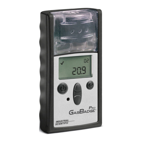
Page 9: Display Overview
Display Overview LCD Display Panel Overview... -
Page 10: Activation
Zero Initiate screen (for toxic sensors) or Cal Initiate screen (for O sensors) is displayed. If no buttons are pressed, the GasBadge Pro proceeds to the Gas Monitoring screen after the countdown reaches zero. The confidence Checkmark indicator is active at this point, indicating that all... -
Page 11: Operating Quick Start Guides
Operating Quick Start Guides Basic Operating Flowchart... -
Page 12: Configuration Mode Flowchart
Configuration Mode Flowchart... - Page 13 Configuration Mode Flowchart (Continued)
-
Page 14: General Operation
General Operation Normal operation modes include the following: • Gas Monitoring • Days Since/Until Calibration (if enabled) • Zero Initiate (if enabled) • Calibration (if enabled) • Peak Reading • Time Weighted Average (TWA) Reading (except O • Short Term Exposure Limit (STEL) Reading (except O •... -
Page 15: Days Since Calibration
In the presence of a gas concentration that exceeds the low or high level threshold, the instrument enters an alarm screen. Alarm detection in any of the instrument’s normal operating screens – the battery life, peak, or initiate print screens – forces a transition back to the Gas Monitoring screen. -
Page 16: Days Until Calibration
This screen is displayed if the View Cal Date option is turned on, and the View Last/Next Cal Date option is set to view the last cal date. Days Since Calibration Screen Actions Available from the Days Since Calibration Screen Action Response If View Cal Date is set, go to Days Since/Until... -
Page 17: Zero Initiate (Toxic Sensors Only - For Oxygen Sensors, Skip To Calibration Section)
Actions Available from the Days Until Calibration Screen Action Response If Zero In Field is enabled, go to Zero Initiate screen (for toxic sensor) or Cal Initiate (for O Up Arrow sensor). button press If Zero In Field is disabled, go to Peak Gas Reading screen. -
Page 18: Zeroing Failed
Zeroing Failed The Zeroing Failed screen (with the Zero icon and a flashing Warning icon) indicates to the user that the zeroing process could not achieve a sensor offset correction within the allowable limits of the instrument. The instrument is placed in periodic alarm (one alarm burst every Zeroing Failed Screen 15 seconds) while in this condition. -
Page 19: Calibration
Calibration Gas detection instruments are potentially life-saving devices. Recognizing this fact, Industrial Scientific Corporation recommends that a functional (“bump”) test be performed on every instrument prior to each day’s use. A functional test is defined as a brief exposure of the monitor to a concentration of gas(es) in excess of the... - Page 20 On the Calibration screen, the Cal Gas Bottle icon flashes, notifying you to apply the gas concentration shown and press Enter to begin calibration. Calibrate using a flow rate of 0.5 LPM. Upon completion of calibration, the instrument beeps once and either the Cal Passed () or Cal Failed (!) icon is displayed along with the sensor span reserve.
-
Page 21: Calibration Passed
Calibration Passed The Calibration Passed screen indicates that the instrument spanning process has completed successfully. The primary character display indicates the sensor span reserve. Checkmark indicator is active to announce that the calibration process has passed. Once the Enter button is pressed, or after 30 seconds Cal Passed Screen displaying this screen, a transition is made back to the Zero or Cal Initiate screen. -
Page 22: Bump Test
Actions Available from the Calibration Failed Screen Cal Failed (!) Response Action Toxic Sensor Oxygen Sensor Enter Go to Zeroing In Process Go to Cal Leveling Off button screen. screen. press Bump Test The bump test screen allows the user to initiate and perform a manual bump test of the instrument using calibration gas. -
Page 23: Twa Gas Reading Screen
Pressing the Enter button on the Peak Gas Reading screen clears the peak value. On O instruments, the depletion peak is cleared to 20.9%. NOTE: The GasBadge Pro retains the maximum gas reading (for a toxic sensor) and the minimum gas reading (for an O sensor) for later viewing. - Page 24 appropriate. Clearing the TWA from this menu creates a new datalog session. The TWA value is saved in non-volatile memory when power is turned off. TWA Screen and TWA Alarm Screen If there is a TWA alarm, the Alarm indicator is also active, and the LED, speaker, and vibrator all act as if a low gas alarm had occurred.
-
Page 25: Stel Gas Reading Screen
STEL Gas Reading Screen The STEL Gas Reading screen is one of the normal operating states. The primary character display of the instrument presents the STEL over the last 15 minutes. The STEL reading is accompanied by the PPM concentration indicator and the STEL indicator. - Page 26 Actions Available from the Create Session Screen Action Response Enter button Create a new datalog session. press Up Arrow Go to Gas Monitoring screen. button press 30 second Go to Gas Monitoring screen. timeout The logging interval is programmable from 2 seconds to 5 minute in 2 second increments.
-
Page 27: Event Log
Event Log The GasBadge Pro stores alarm events in non-volatile memory. The last 15 gas alarm events are stored with continuous-loop logging. Alarms occur if the... -
Page 28: Shutdown Password Screen
Shutdown Password Screen If there is a security code set (i.e., the value is greater than 0), and if the Always On option is enabled, holding the Mode button for 5 seconds on the Shutdown screen goes to the Shutdown Password screen. -
Page 29: Configuration Mode
Configuration Mode Configuration modes include the following screens: • Security Code Setting • Calendar Setting • Zero/Calibrate Initiate • Data Log Interval • Days Since/Until Calibration • Display Setting • Initiate Print • Always On Option • Low Alarm Setting •... -
Page 30: Security Code
Security Code The Security Code Screen is the first screen in the configuration mode which is outside of the normal operating mode. The configuration mode is reached from the countdown screen by pressing the Up and Down Arrow buttons simultaneously. The default security code is 000. -
Page 31: Calibration
Calibration For information on calibration, refer to the Calibration section on page 19. Days Since Calibration For information on viewing the Days Since Calibration screen, refer to the Days Since Calibration section on page 15. Days Until Calibration For information on viewing the Days Until Calibration screen, refer to the Days Until Calibration section on page 16. -
Page 32: Low Alarm Setpoint
Low Alarm Setpoint The Low Alarm Setpoint screen is used to set the threshold for the low alarm. For an oxygen sensor, this threshold indicates the depletion oxygen concentration at which the alarm is activated. On entering this state, the primary character display shows the present threshold value. - Page 33 Down Arrow Decrement value on display. button press Low-level and high-level alarms have a setpoint stored in the GasBadge Pro. The calibration gas concentration setpoint is also stored in the instrument. Default Setpoints for GasBadge Pro Sensors High STEL...
-
Page 34: High Alarm Setpoint
High Alarm Setpoint The High Alarm Setpoint screen is used to set the threshold for the high alarm. For an Oxygen sensor, this threshold indicates the enrichment oxygen concentration at which the alarm is activated. On entering this state, the primary character display shows the present threshold value. -
Page 35: Twa Alarm Setpoint
Edit Mode Options for the High Alarm Setpoint Screen Action Response Cancel changes, stop blinking value, go to Mode button press TCM. Save changes, stop blinking value, go to Enter button press TCM. Up Arrow button Increment value on display. press Down Arrow Decrement value on display. -
Page 36: Set Twa Interval
Editing a Value: All characters of the primary display blink to indicate that they are ready to change. The threshold is incremented by pressing the Up Arrow button and is decremented by pressing the Down Arrow button. Simple momentary presses increment/decrement the value by 1 unit. Holding either button for an extended time increments/decrements the value much faster. -
Page 37: Stel Alarm Setpoint
Up Arrow button Go to STEL Alarm Setpoint screen. press Down Arrow Go to TWA Alarm Setpoint screen. button press 30 second timeout Go to Gas Monitoring screen. Editing a Value: All characters of the primary display blink to indicate that they are ready to change. - Page 38 Actions Available from the STEL Alarm Setpoint Screen (TCM) Action Response Mode button press Go to Gas Monitoring screen. Enter button press Blink value. See the edit options table. Up Arrow button Go to Cal Gas Setup screen. press Down Arrow Go to TWA Interval screen.
-
Page 39: Set Calibration Gas Concentration
Set Calibration Gas Concentration This screen allows the user to set the calibration gas concentration. On entering this state, the primary character display shows the present calibration gas value. To edit the calibration gas value, press the Enter button. Cal Gas Concentration PPM and %Vol Setup Screens Actions Available from the Set Cal Gas Concentration Screen (TCM) Action Response... -
Page 40: Set Clock
value rolls over to the maximum. Pressing the Mode button aborts the editing process and takes the user to the TCM. Edit Mode Options for the Set Cal Gas Concentration Screen Action Response Cancel changes, stop blinking value, go to Mode button press TCM. - Page 41 Editing a Value – Hours: The hours value blinks to indicate that it is the value to be edited. The hours value is incremented by pressing the Up Arrow button and decremented by pressing the Down Arrow button. Simple momentary presses increment/decrement the value by 1 unit.
-
Page 42: Set Calendar Month/Day
Down Arrow Decrement value on display. button press Set Calendar Month/Day This screen allows the user to set the month, day, and year. On entering this state, the primary character display shows the present month and day, and also shows the check mark and month icons. - Page 43 Edit Mode Options (Month) for the Set Calendar Month/Day Screen Action Response Cancel changes, stop blinking value, go to Mode button press TCM. Save month, stop blinking month, blink days, Enter button press remove month icon, display day icon, and go to edit day options table.
-
Page 44: Set Security Code
Editing a Value - Year: This screen displays the year as “20xx.” The year value blinks to indicate that it is the value to be edited. The year value is incremented by pressing the Up Arrow button and is decremented by pressing the Down Arrow button. - Page 45 Blink value. See the edit options table. Enter button press (Default value is 000.) Up Arrow button Go to Set Datalog Interval screen. press Down Arrow Go to Set Calendar screen. button press 30 second timeout Go to Gas Monitoring screen. Editing a Value: Upon pressing the Enter button, the first digit of the code blinks, indicating that it may be edited by the user with the Up and Down Arrow buttons.
-
Page 46: Set Data Log Interval
Set Data Log Interval This screen allows the user to set the datalog interval, from 2 to 300 seconds (in 2 second increments). On entering this state, the primary character display shows the current logging interval in seconds, the check, the time, and the logging icon. To edit the logging interval, press the Enter Set Datalog Interval Screen button. -
Page 47: Primary Display Setting
Edit Mode Options for the Set Data Log Interval Screen Action Response Mode button press Cancel changes, stop blinking value, go to TCM. Save changes, stop blinking value, and go to Enter button press TCM. Up Arrow button Increment value on display. press Down Arrow Decrement value on display. - Page 48 Actions Available from the Primary Display Setting Screen (TCM) Action Response Mode button press Go to Gas Monitoring screen. Blink value. See the edit options table. Enter button press (Default is Monitor PPM/% Vol.) Up Arrow button Go to Always On Option screen. press Down Arrow Go to Logging Interval screen.
-
Page 49: Always On Option
Always On Option The Set Always On screen is used to disable turning off of the instrument. The rightmost character of the primary display shows either a “0” or a “1.” A value of “0” indicates that the instrument can be powered off by the user and a value of “1”... -
Page 50: Set Confidence Indicator
“1.” Pressing the Mode button aborts the editing process and takes the user to the TCM. Pressing the Enter button saves the setting and displays the TCM. Edit Mode Options for the Always On Option Screen Action Response Cancel changes, stop blinking value, go to Mode button press TCM. - Page 51 Actions Available from the Set Confidence Indicator Screen Action Response Mode button press Go to Gas Monitoring screen. Blink value. See the edit options table. Enter button press (Default is “0” = Indicator disabled.) Up Arrow button Go to Alarm Latch Setup screen. press Down Arrow Go to Always On Option screen.
-
Page 52: Alarm Latch Setup
Alarm Latch Setup The Alarm Latch Setup screen is used to toggle the user option of alarm latching. When alarms are latched (1), any gas alarm continues to be indicated to the user, even after the gas concentration subsides. This continues until the user acknowledges the alarm by pressing the Enter button from the Gas Monitoring screen. -
Page 53: Zero In Field Option
Zero In Field Option This screen allows the user to enable/disable the Zero In Field feature (to lock out zeroing) in monitor mode. The default for this option is "1". If set to "1", then zeroing is not locked and the zero initiate menu is available to the user in monitoring mode. -
Page 54: Cal In Field Option
Edit Mode Options for the Zero Lock Screen Action Response Mode button press Cancel changes, stop blinking value, go to TCM. Save changes, stop blinking value, and go to Enter button press TCM. Up Arrow button Toggle option. press Down Arrow Toggle option. -
Page 55: Cal Date View Option Screen
editing process and takes the user to the TCM. Pressing the Enter button saves the setting and displays the TCM. Edit Mode Options for the Cal In Field Option Screen Action Response Cancel changes, stop blinking value, go to Mode button press TCM. - Page 56 30 second timeout Go to Gas Monitoring screen. Edit Mode Options for the Cal Date View Option Screen Action Response Cancel changes, stop blinking value, go to Mode button press TCM. Save changes, stop blinking value, and go to Enter button press TCM.
-
Page 57: Calibration Past Due Alarm
Calibration Past Due Alarm This screen allows the user to turn on or off a “calibration past due” alarm. This alarm is active in the Gas Monitoring mode. When the calibration is past due, the cal bottle icon flashes and the instrument beeps every 5 seconds. -
Page 58: Calibration Due Setpoint
Edit Mode Options for the Calibration Past Due Alarm Screen Action Response Cancel changes, stop blinking value, go to Mode button press TCM. Save changes, stop blinking value, and go to Enter button press TCM. Up Arrow button Toggle option. press Down Arrow Toggle option. -
Page 59: Bump In Field Option
momentary presses increment/decrement the value by 1 unit. Holding either button for an extended time increments/decrements the value much faster. Upon reaching the maximum value (365), the display rolls over to the minimum value of 1. Scrolling down below the minimum value rolls over to the maximum. Pressing the Mode button aborts the editing process and takes the user to the TCM. - Page 60 Actions Available from the Bump in Field screen(TCM) Action Response Mode button press Go to Gas Monitoring screen. Blink value. See the edit options table. Enter button press (Default is “0” = Bump in Field disabled If value = 0, Go to Zero/Calibrate initiate screen.
-
Page 61: Bump Overdue Alarm Enable
Bump Overdue Alarm Enable If the bump test option has been enabled, this screen allows the user to enable an alarm that indicates when the instrument is overdue for bump testing. If the bump overdue alarm is enabled, the user will be notified by the appearance of the flashing bump test screen and an audible chirp every 30 seconds. -
Page 62: Bump Test Interval
Edit Mode Options for the Bump Overdue Alarm Screen Action Response Cancel changes, stop blinking value, go to Mode button press TCM. Save changes, stop blinking value, and go to Enter button press TCM. Up Arrow button Toggles value from 0 to 1 or 1 to 0. press Down Arrow Toggles value from 0 to 1 or 1 to 0. -
Page 63: Bump Test Timeout
30 second timeout Go to Gas Monitoring screen. Editing a Value: The value on the primary display blinks to indicate that it is ready to be changed. Pressing the up or down button causes the value to increment or decrement in 0.5 day intervals from 0.5 to 7.0. The default value of this screen is set to 1.0 days. - Page 64 Blink value. See the edit options table. Enter button press (Default is “45” = Bump Test Timeout is 45seconds. Up Arrow button Go to Zero/Calibrate Initiate screen press Down Arrow Go to Bump Test Interval screen. button press 30 second timeout Go to Gas Monitoring screen.
-
Page 65: The Ds2 Docking Station (Optional Accessory)
The DS2 Docking Station (Optional Accessory) The DS2 Docking Station is available for the GasBadge Pro instrument. The DS2 provides the ultimate flexibility for managing your gas monitors, where ever they are used. The DS2 provides automatic calibrations, bump testing, record keeping and instrument diagnostics for your GasBadge Pro instrument. -
Page 66: Battery Failure
Battery Failure Screen Sensor Missing Error The GasBadge Pro performs a self-test without initiation from the operator. The self test occurs at intervals of 2 seconds. The self test ensures the presence of the sensor and validates that the instrument is working properly. -
Page 67: Unexpected Instrument Error
Unexpected Error Screen Replacing Parts The battery and of the GasBadge Pro may be replaced as a water/dust sensor barriers part of the routine maintenance schedule. These items are shown in the detailed components drawing below, with reference callouts 2 and 3, respectively. To... - Page 68 Item Part # Description 17051666 Case Screws (Australia and MSHA) 17120528 Suspender Clip 17120908 Belt Clip 17126335 Clip attachment screw 17126350 PCB mounting screw 17124504 Replacement water/dust barriers (5 count) 17120635 Sensor Gasket...
- Page 69 Detailed Components Drawing Showing Replacement Parts...
-
Page 70: Replacing The Sensor
Replacing the Sensor To replace a GasBadge Pro sensor, follow the steps below. 1. Turn off the instrument. 2. Remove the four screws holding the case halves together. 3. Place the instrument face down on a flat surface. 4. Locate the sensor tail connector on the printed circuit board (PCB) and remove it. - Page 71 Sensor Replacement Components...
-
Page 72: Sensor Specifications
The accuracies stated below are over the entire operating range of the sensor and defined over the range of calibration. Sensor Specifications for the GasBadge Pro % Accuracy Sensor temperature... - Page 73 -20 to +40 ± 10.0 ± 15 0 – 30 ppm 0.1 ppm 20 – 95 % (-4 to 104) -20 to +40 ± 15 0 – 2,000 ppm 1 ppm -2% to +16% 20 – 95 % (-4 to 104) 1 –...
-
Page 74: Ordering Information - Accessories And Peripheral Equipment
Ordering Information – Accessories and Peripheral Equipment Part Numbers for the GasBadge Pro and Related Components Part # Description 18100060-1 GasBadge Pro with carbon monoxide (CO) sensor 18100060-2 GasBadge Pro with hydrogen sulfide (H S) sensor 18100060-3... -
Page 75: General Specifications
General Specifications Item Description Rugged, water-resistant polycarbonate shell with protective concussion-proof Case overmold. RFI resistant. 3.7″ × 2.0″ × 1.1″ (94.0 mm × 50.8 mm × 27.9 mm) (H×W×L) Dimensions Weight 3 oz (85 g) HCN, Sensors and CO/H null CO range: 0-1,500 ppm in 1 ppm increments S range:... -
Page 76: Warranty Policy
Industrial Scientific Corporation’s portable GasBadge Pro gas monitoring instrument is warranted to be free from defects in material and workmanship under normal and proper use and service for as long as the instrument is supported by Industrial Scientific Corporation. The above warranty does not include the sensors, battery, or filters; however the sensors carry their own separate warranty. -
Page 77: Agency Certifications
It is expressly agreed by the parties that any technical or other advice given by Industrial Scientific with respect to the use of the goods or services is given without charge and at Buyer’s risk; therefore, Industrial Scientific assumes no obligations or liability for the advice given or results obtained. -
Page 78: Contacts
服务热线:+86 400 820 2515 如 需 查 找 就 近 的 产 品 经 销 商 或 Industrial Scientific 服 务 中 心 或 业 务 办 事 处 , 请 访 问 我 们 的 网 站 www.indsci.com。...
Need help?
Do you have a question about the GasBadge Pro and is the answer not in the manual?
Questions and answers