Industrial Scientific Radius BZ1 Product Manual
Area monitor
Hide thumbs
Also See for Radius BZ1:
- Product manual (104 pages) ,
- Quick start manual (3 pages) ,
- Replacement instruction (2 pages)

Related Manuals for Industrial Scientific Radius BZ1


Summary of Contents for Industrial Scientific Radius BZ1
- Page 1 Product Manual The Essential Guide for Safety Teams and Instrument Operators Edition: 11 January 31, 2020 Part Number: 17155915-1...
- Page 2 Industrial Scientific Corporation, Pittsburgh, PA USA Industrial Scientific Co., Ltd. Shanghai, China © 2016, 2017, 2018, 2019, 2020 Industrial Scientific Corporation All rights reserved. Published 2020. Version 13 www.indsci.com/radius...
-
Page 3: Table Of Contents
Contents General Information ............................1 Certifications .............................. 1 Warnings and Cautionary Statements ....................... 2 Recommended Practices ........................... 4 First-use Checklist ..........................4 Placement Guidelines ..........................4 Gas and site factors ........................... 4 Wireless and GPS factors ........................4 Maintenance ............................5 Settings .............................. - Page 4 Quick-status ............................. 14 Compatibilities ............................14 Batteries and Power Supplies ......................14 Sensors ............................... 15 Docking Station and Software ......................15 Sample Tubing Kits ..........................16 Specifications............................16 Instrument............................16 Batteries .............................. 17 Sensors ............................... 17 Getting Started ............................29 Unpacking ..............................
- Page 5 RGX Gateway and TGX Gateway ....................... 58 Smart-device gateway ......................... 59 Gas Readings ............................59 Operating the Instrument ......................... 60 Information............................60 Utilities ..............................60 Alarms, Warnings, and Indicators ......................62 Alarms ..............................62 Warnings ............................. 65 Indicators ............................. 65 Resolving Failures and Errors ........................
- Page 6 Table 2.4 Battery specifications ........................17 Table 2.5 Sensor specifications ........................18 Table 3.1 Package contents ........................29 Figure 3.1.A Hardware overview Radius BZ1 (front view; diffusion) ............30 Figure 3.1.B Hardware overview Radius BZ1 (back view; aspirated) ............31 Figure 3.2 Setup ............................32 Figure 3.3 Display overview (operational instrument) ..................
- Page 7 Figure 6.1 Home screen variations ......................59 Figure 6.2 Operation instruction ........................61 Figure 6.3 Alarm-signal intensity ......................... 62 Figure 6.4 Example alarm and peer-alarm display-screens ................. 63 Figure 6.5 Alarms, possible causes, and relative signal intensity ..............64 Figure 6.6 Example warning display-screens ....................65 Table 6.1 Warnings and indicators;...
-
Page 9: General Information
The following apply to instruments that are to be used in compliance with the CSA certification: Radius BZ1 Area Monitor is CSA-certified according to the Canadian Electrical Code for use in Class I, Division 1 and Zone Classified Hazardous Locations within an ambient temperature range of T : -20 °C to +55 °C. -
Page 10: Warnings And Cautionary Statements
In addition to the certifications listed below, refer to the Industrial Scientific websites for the most up-to-date information about wireless product certifications. Table 1.2 Wireless certifications and directives Agency or authority Identification number or Country or region registration number CE Radio Equipment Directive... - Page 11 CHARGER L'ACCUMULATEUR DANS UN EMPLACEMENT DANGEREUX. The compatible charging power supply (17155923) and cord is to be connected and used only in a nonhazardous location. When the Radius BZ1 or Radius Base is in a hazardous location, the charging power supply cap must be installed...
-
Page 12: Recommended Practices
• Train instrument users. Placement Guidelines To develop a placement plan for each unique, in-field application of Radius BZ1 instruments, keep in mind all relevant gas, site, and LENS™ Wireless (Linked Equipment Network for Safety) factors, which include but are not limited to the following. -
Page 13: Maintenance
Table 1.4 Range guidelines for LENS Wireless connections by LENS power mode setting Line-of-sight distance, maximum World setting CE RED setting Radius BZ1 to Radius BZ1 300 m (328 yd) 185 m (202 yd) Radius BZ1 to Ventis Pro 100 m (109 yd) -
Page 14: Settings
Table 1.5. These recommendations are provided to help support worker safety and are based on field data, safe work procedures, industry best practices, and regulatory standards. Industrial Scientific is not responsible for determining a company’s safety practices or establishing its safety policies, which may be affected by the directives and recommendations of regulatory groups, environmental and operating conditions, instrument use patterns and exposure to gas, and other factors. -
Page 15: Biased Sensors
The instrument performs a self-test during power on. When the instrument remains on, it will complete a self-test during each 12-hour period. The self-test can also be completed on demand through settings. Note: The use of calibration gases not provided by Industrial Scientific may void product warranties and limit potential liability claims. Biased Sensors The functionality of biased sensors is dependent on their receipt of continuous power. -
Page 16: Remote Sampling
When a biased sensor is in use and the Radius BZ1 emits a low battery warning or a low backup battery warning, complete the steps noted below. Low battery warning Low backup battery warning • Replace the SafeCore Module’s backup battery. -
Page 17: Care And Storage
• Industrial Scientific recommends that the SafeCore Module be stored in the Radius Base; this will help conserve the module’s backup battery, a power source that maintains the module's clock and is needed when biased sensors are installed. -
Page 19: Product Information
• Optionally provides instructional messages for a variety of specific hazards. Team-based safety As part of a LENS™ Wireless group, the Radius BZ1 can also operate as a “peer” equipment item. Peer instruments share with one another gas readings, alarms, and other instrument events. This sharing allows workers and their supervisors to learn of hazardous conditions and team members who may be in distress. -
Page 20: Key Features
Instrument data RGX Gateway iNet Now users (live monitoring and subscription-based alerts) Figure 2.1 Industrial Scientific connected safety system Key Features Alarms Gas alarms The instrument will alert workers to the following types of alarm events: gas present, STEL, and TWA using two signal options (visual and audible) and up to four distinct audio patterns. -
Page 21: Connectivity
LENS Wireless LENS Wireless from Industrial Scientific allows gas-detection instruments and other peer equipment items to communicate with one another and form LENS groups. LENS peers can connect to named or ad hoc LENS groups by scanning for nearby groups and joining automatically, via assignment to a named LENS group, and specific instrument types can connect via NFC (Near Field Communication) and instrument pairing. -
Page 22: Quick-Status
Compatibilities Batteries and Power Supplies The battery pack that powers the Radius BZ1 Area Monitor is encased in the Radius Base. It must be charged in a nonhazardous environment using its dedicated power supply and power cord. -
Page 23: Sensors
(see "Mfg. date" YYYY-MM). Biased sensor (see Chapter 1, "Recommended Practices, Biased Sensors”). Docking Station and Software The SafeCore Module is compatible with the DSX™ Docking Station and is supported by iNet or DSSAC software from Industrial Scientific. -
Page 24: Sample Tubing Kits
Specifications Instrument The Radius BZ1 takes gas readings every second and records readings-related data at its settable interval. Data are stored in the instrument data log, which has these characteristics: • Capacity for approximately 90 days of data for a unit that has six installed sensors and is set to record data every ten seconds. -
Page 25: Batteries
Batteries Provided below are battery specifications, which include run time, charge time, charging temperature requirements, and expected lifetime. Table 2.4 Battery specifications Battery Radius Base battery pack SafeCore Module battery Battery type Nickel Metal Hydride Lithium Thionyl Chloride (Li-SOCl Battery lifetime 2 years 2+ years —... - Page 26 Table 2.5 Sensor specifications Gas type (abbreviation) Part number Ammonia (NH 17156650-6 Properties Category Toxic and combustible Technology Electrochemical DualSense capable Installation locations Operating conditions Temperature range -20 to +40 °C (-4 to +104 °F) RH range 15–95% Performance Sensitivity Measurement range 0–500 ppm Measurement resolution...
- Page 27 Table 2.5 Sensor specifications Gas type (abbreviation) Part number Carbon Dioxide (CO 17156650-Q Properties Category Toxic Technology Infrared DualSense capable Installation location 3 or 4 Operating conditions Temperature range -20 to +50 °C (-4 to +122 °F) RH range 0-95% Performance Sensitivity Measurement range...
- Page 28 Table 2.5 Sensor specifications Gas type (abbreviation) Part number Carbon Monoxide (CO) 17156650-1 Properties Category Toxic Technology Electrochemical DualSense capable Installation location Operating conditions Temperature range -20 to +50 °C (-4 to +122 °F) RH range 0-95% Performance Sensitivity Measurement range 0-1500 ppm Measurement resolution 1ppm...
- Page 29 Table 2.5 Sensor specifications Gas type (abbreviation) Part number Carbon Monoxide, high range (CO) Carbon Monoxide, low Hydrogen interference CO-Low H 17156650-H 17156650-G Properties Category Toxic Toxic Technology Electrochemical Electrochemical DualSense capable Installation locations Operating conditions -20 to +50 °C -20 to +50 °C Temperature range (-4 to +122 °F)
- Page 30 Table 2.5 Sensor specifications Gas type (abbreviation) Part number Carbon Monoxide and Hydrogen Sulfide (CO and H 17156650-J Properties Category Toxic Technology Electrochemical DualSense capable Installation locations Operating conditions -20 to +55°C Temperature range -20 to +50 °C (-4 to +122 °F) (-4 to +131°F) RH range 15–90%...
- Page 31 Table 2.5 Sensor specifications Gas type (abbreviation) Part number Chlorine (Cl Hydrogen (H 17156650-7 17156650-C Properties Category Toxic Toxic Technology Electrochemical Electrochemical DualSense capable Installation locations Operating conditions -20 to +50 °C -20 to +50 °C Temperature range (-4 to +122 °F) (-4 to +122 °F) RH range 15–90%...
- Page 32 Table 2.5 Sensor specifications Gas type (abbreviation) Part number Hydrogen Cyanide (HCN) Hydrogen Sulfide (H 17156650-B 17156650-2 Properties Category Toxic Toxic Technology Electrochemical Electrochemical DualSense capable Installation locations Operating conditions Temperature range -20 to +40 °C -20 to +50 °C (-4 to +104 °F) (-4 to +122 °F) RH range...
- Page 33 Table 2.5 Sensor specifications Gas type (abbreviation) Part number LEL (Methane) LEL (Pentane) 17156650-L 17156650-K Properties Category Combustible Combustible Technology Catalytic Catalytic DualSense capable 3 or 4 3 or 4 Installation locations Operating conditions Temperature range -20 to +55°C -20 to +55°C (-4 to +131°F) (-4°F to +131°F) RH range...
- Page 34 Table 2.5 Sensor specifications Gas type (abbreviation) Part number Nitric Oxide (NO) Nitrogen Dioxide (NO 17156650-D 17156650-4 Properties Category Toxic Toxic Technology Electrochemical Electrochemical DualSense capable Installation locations Operating conditions Temperature range -20 to +50 °C -20 to +50 °C (-4 to +122 °F) (-4 to +122 °F) RH range...
- Page 35 Table 2.5 Sensor specifications Gas type (abbreviation) Part number Oxygen (O Phosphine (PH 17156650-3 17156650-9 Properties Category Oxygen Toxic Technology Electrochemical Electrochemical DualSense capable Installation locations Operating conditions Temperature range -20 to +55 °C -20 to +50 °C (-4 to +131 °F) (-4 to +122 °F) RH range 5–95%...
- Page 36 Table 2.5 Sensor specifications Gas type (abbreviation) Part number Sulfur Dioxide (SO Volatile Organic Compounds (VOC) 17156650-5 17156650-R Properties Category Toxic Toxic Technology Electrochemical PID (10.6 eV) DualSense capable 3 or 4 Installation locations Operating conditions Temperature range -20 to +50 °C -20 to +50 °C (-4 to +122 °F) (-4 to +122 °F)
-
Page 37: Getting Started
Unpacking A shipment may include the items listed below in Table 3.1. Each item should be accounted for during the unpacking process. If any item is missing or appears to have been damaged, contact Industrial Scientific (see back cover for Contact Information) or an authorized distributor of Industrial Scientific products. -
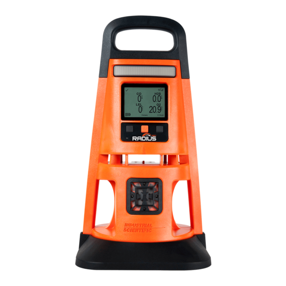
Page 38: Hardware Overview
Handle Lights Display ■ Power button Right button ( ■ Left button ( Gas path (diffusion Ambient-light only) sensor Sensor ports Speaker Handles Boot Figure 3.1.A Hardware overview Radius BZ1 (front view; diffusion) - Page 39 Write-on label (aspirated shown) Air inlet (aspirated only) Module locking screw Intrinsic safety (x2) power port Charging indicator Charging port Handle Boot Air inlet (diffusion Connector only) SafeCore Module port (shown empty) Figure 3.1.B Hardware overview Radius BZ1 (back view; aspirated)
-
Page 40: Setup
Setup Use the supplied screwdriver set to prepare the instrument for operation as described below in Figure 3.2. On the back of the Radius Base, locate Slide the module straight into its port. Push firmly to support the connection of the the SafeCore Module port. -
Page 41: Display Overview
Display Overview As shown below, the main portion of the display is dedicated to gas readings information. Above the gas readings area is a status bar and below it a navigation bar. Status symbols and information display in both bars; the navigation bar also displays control symbols and instructional text. Status bar Gas readings area Navigation bar... - Page 42 Identifies a peer instrument as a Radius BZ1. Identifies a peer instrument as a Ventis™ Pro. Gas readings area This area displays gas-readings information, alarm details, and sensor status messages (e.g., calibration due symbol). Numeric view Text view Gas readings Gas, current reading, and unit of measure.
- Page 43 The navigation bar also displays peer alarms and details about those alarms (event, gas reading, and instrument). At other times, it displays control symbols where each symbol applies to the button directly below it. Navigation bar Network information Identifies an instrument in the LENS peer group that may be experiencing an alarm or a group- Tank 3 peer connection issue.
-
Page 45: Settings
Accessing Settings Radius BZ1 settings, which are stored in the SafeCore Module, can be accessed at any time during operation by simultaneously pressing and holding the instrument's left and right buttons. As shown below, if the security-code screen is activated, settings are protected and you must enter the instrument's security code to access settings. -
Page 46: Settings Overview
When working in settings, the instrument will wait approximately 30 seconds between button presses; when no button is pressed, it will exit the current setting screen and revert to the prior display screen. If that is the home screen, simultaneously press and hold the left and right buttons to re-enter settings. Settings Overview Instrument settings are organized by topic. - Page 47 Status bar When working in settings, the status bar indicates the current topic (Wireless shown here) or the name of the setting that is being edited. It also features the settings symbol and battery indicator. The editing area displays each item that can be set.
-
Page 48: Working In Settings
Peer Lost Warning setting. During editing, the right and left buttons generally perform the same function. Note: The Radius BZ1 will monitor for gas and its alarms will be functional while editing settings. ■ ■... -
Page 49: Reviewing And Editing Settings
Reviewing and Editing Settings The rest of this chapter describes in detail the options available within each settings topic: • Maintenance • Start-up • Operation • Alarm • Sensor • Admin • Wireless From the access instruction and examples provided above, use the instrument buttons to review and adjust the instrument's settings described below in Tables 4.2 through 4.8. -
Page 50: Start-Up Settings
Start-up Settings These settings allow the safety specialist to permit or prohibit all-user access to start-up options, information that will display during the power-on process. ■ ■ Move the Select the Move the highlighted highlight bar highlight bar up option down Table 4.3 Start-up settings Setting... -
Page 51: Alarm Settings
Table 4.4 Operation settings Setting Description and options Permit or prohibit all-user access—during operation—to the information items listed here. To permit access, set the option to "On"; to prohibit access, set it to "Off." Set each item separately. View Instrument Info Set all-user access to view serial numbers, versioning information, installed sensor types, company name, and current user and site assignments. - Page 52 Table 4.5 Alarm settings Setting Description and options Alarm Set the signal type or disable alarm signals. Choose one desired effect from among these options: Option Effect Visual Lights only Audible Speaker only Audible and Visual Speaker and lights No speaker and no lights Note: If Off is selected, the instrument will ask for confirmation Audio Pattern Set the audio pattern for gas alarms;...
-
Page 53: Sensor Settings
Table 4.5 Alarm settings Setting Description and options Allow Shutdown in Use this setting to permit or prohibit instrument shutdown during alarm events. Alarm Option Effect Allows any user to shut down the instrument while it is in alarm. Prohibits shutdown of the instrument when it is in alarm. Alarm Events View details for the most recent alarm events. -
Page 54: Admin Settings
Admin Settings Admin settings allow the safety specialist to control important aspects about how the instrument communicates with its operator. For example, a security code can be set to help restrict access to settings. Note: This will restrict access to settings for all users. The safety specialist can also set the display-screen language, maintenance-related warnings, and other items. - Page 55 Table 4.7 Admin settings Setting Description and options Audible Chirp Visual Blue lights Audible and Visual Chirp and blue lights Sync Interval Select the interval for each maintenance due warning. The "sync" interval controls the dock-due warning. Calibration Interval Interval type Value Bump Interval Sync...
-
Page 56: Wireless Settings
Wireless Settings Wireless settings allow the safety specialist to control LENS Wireless functionality. This includes whether instrument data can be transmitted to iNet for live-monitoring access by users of iNet Now, and how the instrument will behave with respect to its peers, the gas-detection instruments within the LENS group. - Page 57 Default Use the Industrial Scientific encryption key. Custom Use an encryption key other than the Industrial Scientific default option. This option requires the use of iNet or DSSAC. View Wireless Peers Set whether all users can view gas readings—during operation—for peer instruments that are within the instrument's assigned LENS group.
- Page 58 The instrument will not emit an alarm when a peer instrument is lost. Acknowledge Peer Lost When the Peer Lost Warning (above) is set to "On", use the Acknowledge Peer Lost feature to allow the instrument operator to turn off the LED and audible signals when a peer is lost.
-
Page 59: Power
Power Charging the Battery Power On Shutdown Maintaining Battery Charge Charging the Battery Before first use and as needed—in an area known to be nonhazardous—charge the Radius Base battery ® as described below in Figure 5.1. Charging can be done whether or not a SafeCore Module is installed. -
Page 60: Power On
The alarm muffler accessory from Industrial Scientific may be used to further diminish the volume; be sure to remove the muffler before instrument operation. The instrument will perform a self-test; its operator should observe the instrument and its display to verify the unit is functioning as expected. - Page 61 The unit emits a beep. Verify that the If the unit fails any part of its self-test, an error message will display. If the unit or its speakers are functional. operator detect problems, contact Industrial Scientific. Start-up sequence Set date and time Instrument information ■...
- Page 62 Note: A failed pump test may indicate a problem in the sampling line. Check and correct for cracks or other damage, debris, and improper installation in these areas: tubing, all sampling line connections, and the pump inlet water barrier. Maintenance information Gas information The dock information (above) indicates The calibration information (above)
-
Page 63: Shutdown
10 minutes of high alarm per day. Approximate run time when used with the Radius BZ1 Area Monitor that has a fully charged battery powering a diffusion unit that is operating at room temperature (25 °C [77 °F]) with CO, H... -
Page 65: Operation
• Verify the instrument's alarms are not turned off. Contact a supervisor if this message appears in the display's navigation bar: " Alarms Off." • If a compatible power supply from Industrial Scientific is in use, verify that the instrument is receiving power by checking the instrument display screen for the power-supply symbol ( ). -
Page 66: Lens Wireless
(EMI) near the instrument. Live Monitoring iNet Now, a service of Industrial Scientific, is part of a wireless system that provides for the live monitoring of gas-detection instruments. Instrument data is uploaded, via a compatible gateway, to iNet. From iNet, the safety team, using iNet Now, can monitor gas hazards on a live basis. -
Page 67: Smart-Device Gateway
Note: Group size may vary based on gateway settings or other conditions. Smart-device gateway Data from a Radius BZ1 can reach iNet through a smart-device gateway when the following are true. • The smart device is running the iNet Now Sync App. -
Page 68: Operating The Instrument
Operating the Instrument From the home screen, a series of display screens may be accessible during operation. Some are purely informational while others provide access to maintenance utilities such as bump testing and calibration; options vary based on instrument settings. Information Information screens display briefly and may include: •... - Page 69 Instrument information Maintenance information (Calibration and span format) (Docking format) — — — — — — Next display Next display Next display screen screen screen Gas information Gas information (continued) Zero utility — — — — — — Next display Next display Next display screen...
-
Page 70: Alarms, Warnings, And Indicators
Treat all alarms, warnings, and indicators seriously and respond according to company policy. Alarms Alarms notify instrument operators of danger. Alarm intensity is based on the event type and its source. The Radius BZ1 has alarms of four intensities; from highest to lowest they are: • High alarm • Low alarm •... - Page 71 Full-screen format Readings format (numeric view) Peer alarm format indicate the in-alarm peer instrument is Radius BZ1 or a Ventis Pro, respectively. Figure 6.4 Example alarm and peer-alarm display-screens The display screens shown above feature the symbols for a high alarm (...
- Page 72 Peer gas present (high-alarm event) Peer STEL event STEL Peer man down MAN DOWN Peer panic PANIC Peer Low Alarm Peer gas present (low-alarm event) Peer TWA event Figure 6.5 Alarms, possible causes, and relative signal intensity When displayed in the peer alarm format, the in-alarm instrument is a Ventis Pro. The example below describes and illustrates the sharing of alarm information for instruments that are operating as peers in a LENS group.
-
Page 73: Warnings
Warnings Warnings notify the instrument operator of a condition that needs attention. Warnings turn on and off repeatedly. The more urgent the warning, the shorter the time between on-off occurrences: a warning that repeats every ten seconds is more urgent than a warning that repeats every thirty seconds. -
Page 74: Resolving Failures And Errors
When addressing any failure, always respond according to your company safety policy. Some failures and errors are easily resolved by qualified personnel as described below in Table 6.2. For other errors or failures, contact Industrial Scientific. When a recommended action suggested below requires maintenance or service, complete the work in an area known to be nonhazardous and follow all other instructions provided in "Maintenance"... - Page 75 The numeric error code indicates a specific issue or type of issue. When the error is described on the display screen, qualified personnel can attempt to resolve the issue. If no text accompanies the error code, contact Industrial Scientific or an authorized service center for assistance.
- Page 76 Table 6.2 Failures and errors Calibration results indicate the sensor’s span reserve percentage. When that The sensor failed calibration. value is less than 50%, the sensor will not pass calibration and is due for replacement. If the span reserve percentage indicates the sensor is greater than 50% check for the following: •...
-
Page 77: Maintenance
Tones emitted from the speaker during maintenance are lower in volume compared to the audible alarm signals. The alarm muffler accessory from Industrial Scientific may be used to further diminish the volume; be sure to remove the muffler before instrument operation. -
Page 78: Supplies And Preparation
Supplies and Preparation Use Figure 7.1 as a guide to gathering supplies and preparing the calibration gas cylinders. Supplies • Calibration tubing (shipped with the instrument). • Calibration cup (shipped with diffusion instruments only). • Calibration gas cylinders suitable for the installed sensors and the instrument's calibration gas settings. - Page 79 Calibration cup Calibration apply gas For diffusion units (shown), slide the To start the flow of gas, turn the prepared calibration cup into the gas regulator's knob in a counterclockwise Optionally skip the sensor. path. Press firmly; verify that the direction.
- Page 80 Calibration cup Bump test utility — For diffusion units (shown), slide the prepared calibration cup into the gas path. + Hold Press firmly; verify that the calibration cup edge is flush with the surface of the Start the utility SafeCore Module. For aspirated units, connect the calibration tubing to the pump inlet Bump test apply gas Bump test results...
-
Page 81: Service And Warranty
Warranty Service Service tasks that can be completed by Industrial Scientific customers are described in this manual. Table 8.1 indicates which parts and components are customer replaceable. All other service tasks should be performed only by Industrial Scientific or an authorized service center. -
Page 82: Instruction
Instruction Figure 8.1 provides disassembled views of the instrument, the Radius Base and SafeCore Module, identifying their parts and components. Use Table 8.1 to determine which items are customer replaceable and identify their part names and part numbers. SafeCore Module Radius Base Figure 8.1 Parts diagram for SafeCore Module and Radius Base Table 8.1 Parts table for SafeCore Module and Radius Base... - Page 83 Table 8.1 Parts table for SafeCore Module and Radius Base Diagram Part name Part Notes number Radius Base — Radius Base Varies Base without SafeCore Module. Calibration cup and tubing kit 18109498 Speaker grill kit 18109444 Includes speaker grill and replacement screws. Torque: 0.81 newton m (115 ounce-force inch).
- Page 84 Power off the instrument before disassembling or performing any service task. Speaker grill and dust barrier service Speaker grill removal Speaker dust barrier replacement (if needed) Use the supplied screwdriver set to Holding the edge of the grill, pull it away Peel off the dust barrier and discard.
- Page 85 Port cap replacement (charging port cap shown) Open the charging port by removing its Gently pull on the cap to detach it from To attach the replacement port cap, cap. the instrument. place its loop around the port's casing. Boot replacement Carefully place the instrument face down.
- Page 86 Power off the instrument before disassembling or performing any service task. Module removal — Use the supplied screwdriver set to loosen the two locking, captive screws on the To remove the module from its port, back of the SafeCore Module. To remove and replace the screws, use the SafeCore pull it straight away from the base.
- Page 87 Sensor dust barrier replacement — Place the sheet on the work surface and scrape lightly to the barrier’s edge. Using your fingers or needle-nose tweezers, peel off the used dust barrier Gently lift to expose a portion of its adhesive back. Peel the barrier from the sheet. and discard.
- Page 88 Module installation Visually inspect the SafeCore Module With the SafeCore logo facing towards Using the supplied screwdriver set, connector (circled) for dirt and debris. you and right-side up, slide the module tighten both module screws. Push the Clean with compressed air as needed. straight into its port.
-
Page 89: Warranty
(including negligence), strict liability, products liability or any other theory of liability, will be limited to the lesser of Buyer’s actual damages or the price paid to Industrial Scientific for the Products that are the subject of Buyer’s claim. All claims against Industrial Scientific must be brought within one year after the cause of action arises, and Buyer expressly waives any longer statute of limitations. -
Page 91: Supplemental Information About Gases And Sensors
Appendix A Supplemental Information about Gases and Sensors Cross Sensitivity and Toxic Gases A sensor is designed to detect for and measure the presence of a particular gas, the "target gas"; however, it may also respond to other gases. When this is the case, the sensor is said to have "cross-sensitivity" to another gas, which will interfere with the target-gas readings. -
Page 92: Lel And Combustible Gases
LEL and Combustible Gases Table A.2 provides the Lower Explosive Limit (LEL) for select combustible gases. It also provides correlation factors that can help determine the percentage LEL when the actual gas differs from the gas that was used to calibrate the instrument. For example, if the instrument reads 10% LEL in a pentane atmosphere, and was calibrated to methane, the actual percentage LEL is determined as follows: Locate the table cell where the sample gas (pentane) intersects with the calibration gas (methane). -
Page 93: Extended Run Time Power Supply-Supplemental Information
Appendix B Extended Run Time Power Supply—supplemental information Figure B.1 Control drawing 1810D9387-200 revision 3... -
Page 94: Intrinsically Safe Extended Run Time Power Supply-Supplemental Information
Appendix C Intrinsically Safe Extended Run Time Power Supply—supplemental information Figure C.1 Control drawing 1810D9387-200 revision 3... -
Page 95: Contact Information
Vertriebshändler unserer Produkte oder ein Servicecenter bzw. eine Niederlassung von Industrial Scientific zu finden. Para buscar un distribuidor local de nuestros productos o un centro de servicio u oficina comercial de Industrial Scientific, visite www.indsci.com. 如需查找就近的产品经销商或 Industrial Scientific 服务中 心或业务办事处,请访问我们的网站 www.indsci.com...
Need help?
Do you have a question about the Radius BZ1 and is the answer not in the manual?
Questions and answers