ABB Ability 800xA Series User Manual
Device management foundation fieldbus
Hide thumbs
Also See for Ability 800xA Series:
- Operation (332 pages) ,
- User manual (189 pages) ,
- Operations (36 pages)

Related Manuals for ABB Ability 800xA Series


Summary of Contents for ABB Ability 800xA Series
- Page 1 SYSTEM VERSION 1.0 ABB Ability™ System 800xA - User Manual Device Management FOUNDATION™ Fieldbus LD 810HSE Ex...
- Page 3 SYSTEM VERSION 1.0 ABB Ability™ System 800xA - User Manual Device Management FOUNDATION™ Fieldbus LD 810HSE Ex Document Number: 2PAA114135-610 Release: November 2018 Trace back information Main Publication: Tool version: 5.2.025 Build date: 2018-12-13 at 10:06:27 Domain: ABBPA Workspace, version, checked in: 800xA Main, a195, (working edition) Master: ix-357601-Device Management FOUNDATION Fieldbus LD 810HSE Ex User Manual.xml...
- Page 4 This document contains information about one or more ABB products and may include a description of or a reference to one or more standards that may be generally relevant to the ABB products. The presence of any such description of a standard or reference to a standard is not a representation that all of the ABB products referenced in this document support all of the features of the described or referenced standard.
-
Page 5: Table Of Contents
Table of Contents Table of Contents Safety Summary About this User Manual User Manual Conventions ................. Warning, Caution, Information, and Tip Icons ........Terminology ....................... Released User Manuals and Release Notes ............ Introduction Features of the Linking Device ................1.1.1 Functionality in the HSE Subnet ............ - Page 6 Table of Contents 2.4.3 Connecting the Power Supply ............. 2.4.4 Ethernet Ports ..................2.4.5 Redundancy Link Interface ..............2.4.6 FF-H1 Interfaces .................. Interfaces and Display Elements ............... 2.5.1 Status Indicators - LEDs ..............Commissioning the Hardware ................Replacing a Defective Linking Device in a Redundant Set of Linking Devices .. Adding a Second Linking Device to Form a Redundant Set of Linking Devices .
- Page 7 Table of Contents Appendix A Limits and Performance Data Limits of the HSE Stack ..................A.1.1 Maximum Limits ................... A.1.2 Performance of HSE Communication ..........Limits per H1 Channel ..................A.2.1 General Maximum Limits ..............A.2.2 Performance ..................A.2.3 H1 Slot Time ..................Duration of Redundancy Switch-Over ...............
- Page 8 Table of Contents Appendix D Declarations by the Manufacturer Appendix E Glossary 2PAA114135-610...
-
Page 9: Safety Summary
Safety Summary Safety Summary GENERAL Equipment Environment WARNINGS All components, whether in transportation, operation or storage, must be in a noncorrosive environment. Electrical Shock Hazard During Maintenance Disconnect power or take precautions to insure that contact with energized parts is avoided when servicing. Installation in Hazardous Locations For general requirements on installation, rules for installing, commissioning, maintaining and the appropriate use of... - Page 10 Safety Summary SPECIFIC In a redundant set of Linking Devices, removing the power supply, CAUTIONS the Ethernet cable or a H1 link cable from the primary device causes a redundancy change-over. Before doing so, make sure that the secondary device is operational (and not still booting due to a prior change-over) and the redundancy link interface cable is intact and connected.
- Page 11 Safety Summary SPECIFIC Do not combine different module types in redundant pairs, i.e. do CAUTIONS not combine a Linking Device of type LD 810HSE Ex with other types such as LD 800HSE or LD 800HSE Ex. See page When exchanging an LD 810HSE Ex, make sure not to permute the H1 terminal blocks.
- Page 12 2PAA114135-610...
-
Page 13: About This User Manual
About this User Manual User Manual Conventions About this User Manual Any security measures described in this User Manual, e. g. for user access, password security, network security, firewalls, virus protection, etc., represent possible steps that a user of an 800xA System may want to consider based on a risk assessment for a particular application and installation. -
Page 14: Terminology
The following is a list of terms associated with the FOUNDATION™ Fieldbus Linking Device LD 810HSE Ex that you should be familiar with. The list contains terms and abbreviations that are unique to ABB or have a usage or definition that is different from standard industry usage. -
Page 15: Released User Manuals And Release Notes
About this User Manual Released User Manuals and Release Notes Released User Manuals and Release Notes A complete list of all User Manuals and Release Notes applicable to System 800xA is provided in System 800xA Released User Manuals (3BUA000263*). System 800xA Released User Manuals (3BUA000263*) is updated each time a document is updated or a new document is released. - Page 16 About this User Manual Released User Manuals and Release Notes Table: Available Technical Documentation (Continued) Category Title Description Software Configuration Manual This manual provides detailed instructions on the System 800xA Device configuration and commissioning of Management, FOUNDATION™ FOUNDATION™ Fieldbus subsystems with the Fieldbus Fieldbus Builder FOUNDATION™...
-
Page 17: Introduction
1 Introduction Introduction FOUNDATION™ Fieldbus (FF) is a fieldbus protocol based on international standards and designed for applications in the manufacturing industry, process automation and buildings automation. The guidelines for this fieldbus standard are published by the Fieldbus Foundation. FF defines two communication profiles, H1 and HSE. The H1 profile, with a transmission rate of 31.25 kbit/s, is preferably used for direct communication between field devices in one link (H1 link). -
Page 18: 1 Introduction
In addition, Windows Group Policy allows for system wide security settings to be managed by a redundant pair of domain controllers (if available, otherwise Local Security Policies may be used). ABB has provided a detailing of the standard group policies for a secure deployment of Operations and Engineering. -
Page 19: Features Of The Linking Device
1 Introduction 1.1 Features of the Linking Device Features of the Linking Device The LD 810HSE Ex is a gateway between an FF High Speed Ethernet (FF-HSE) subnet and FF-H1 links. It supports device redundancy. The Linking Device is registered as class 42c of the HSE profile, therefore providing the following functions: •... -
Page 20: Functionality In The Hse Subnet
1 Introduction 1.1 Features of the Linking Device 1.1.1 Functionality in the HSE Subnet • System Management Agent • Network Management Agent • FMS Server providing object access to H1 devices • Publishing/Subscribing of process data from/to H1 devices • Simple Network Time Protocol (SNTP) Server according to HSE specification (SM time synchronization) •... -
Page 21: Redundancy
1 Introduction 1.2 Integration into the Industrial IT System Structure 1.1.4 Redundancy The Linking Device supports device redundancy. In the redundant mode, a set of two physical Linking Devices forms one logical Linking Device. One operates as primary device, the other as secondary device or backup device. Both devices of a redundant set are connected to the same HSE subnet and to the same H1 links. -
Page 22: Product Support
AC 800M, which acts as HSE host on the HSE subnet. It is also possible to configure and commission an FF network that is not linked to an IEC 61131 controller. Product Support Contact the ABB technical support for assistance in reporting the problem. 2PAA114135-610... -
Page 23: Hardware Installation
Hardware Installation Additional information regarding this product is available in MyABB portal (https.//myportal.abb.com/home). It is required that all applicable revisions and rollups for your system are installed either previously or at the same time this firmware is installed. Industrial IT System 800xA SV 5.x/6.x System Software Versions (3BSE037782*) lists all the revisions... -
Page 24: Specifications
2 Hardware Installation 2.2 Specifications Specifications Table 2.2: Specifications of the LD 810HSE Ex Specification Figure Power supply 18 V DC ... 32 V DC; SELV/PELV supply mandatory Typical input current is 200 mA; maximum is 1 A (considering the rush-in current at switch-on). -
Page 25: Installation In Hazardous Locations
2 Hardware Installation 2.3 Installation in Hazardous Locations Installation in Hazardous Locations The LD 810HSE Ex is suitable for use and installation in areas with potentially explosive atmosphere in accordance to both the Division model (North America) and the Zone model (Europe and IEC countries) of hazardous locations. - Page 26 2 Hardware Installation 2.3 Installation in Hazardous Locations • In explosion group IIC and Zone 2, no protected plastic surfaces > 20 cm allowed; in IIB or dust-Ex, 100 cm may be reached. • The hazard of any objects falling onto a Linking Device must be prevented. •...
-
Page 27: Hazardous Location - North American Approval (Culus)
2 Hardware Installation 2.3 Installation in Hazardous Locations • Additional precautions have to be taken if the presence of hydrosulphide, ethylene oxide and/or carbon monoxide is to be expected. Those substances are of a vary low ignition energy. • Icing is not permitted. Table 2.3: Pair of Values for Fieldbus Voltage and Current for Intrinsic Safety Fieldbus (ic): Pair 1... -
Page 28: Hazardous Location - European And International Approval
2 Hardware Installation 2.4 Mounting and Dismounting 2.3.3 Hazardous Location - European and International Approval (ATEX, IECEx) The equipment was assessed as based on the following standards and editions: a) IEC 60079-0:2011 Ed. 6, modified Cor. 2012 + Cor. 2013 / EN 60079-0:2012 + A11:2013 b) IEC 60079-11:2011 Ed. -
Page 29: Mounting
2 Hardware Installation 2.4 Mounting and Dismounting Depending on the installation position, the maximum ambient operating temperature may differ. For detailed information, refer to tables LD 810HSE Ex Maximum Ambient Operating Temperature for Horizontal Installation on page 30 LD 810HSE Ex Maximum Ambient Operating Temperature for Vertical Installation on page 31 or to Specifications on page... - Page 30 2 Hardware Installation 2.4 Mounting and Dismounting To maintain the operating temperature of the Linking Device, ensure that proper ventilation is maintained in the enclosure: • Depending on the installation position, different ambient operating temperatures are allowed. • Clearance between the Linking Device and the adjacent components or side walls of the housing must be adhered to as illustrated in Figure 2.2.
- Page 31 2 Hardware Installation 2.4 Mounting and Dismounting Figure 2.3: LD 810HSE Ex Vertical Installation Position Provide a minimum space of 50 mm to the air inlet or air outlet. Table 2.5: LD 810HSE Ex Maximum Ambient Operating Temperature for Vertical Installation Maximum permissible Maximum number of Maximum fieldbus...
-
Page 32: Connection Diagram
2 Hardware Installation 2.4 Mounting and Dismounting The maximum permissible ambient temperature values are also valid for a 180° rotated installation position. 2.4.2 Connection Diagram The following connection diagram shows an overview on the different plugs and interfaces: Figure 2.4: LD 810HSE Ex Connection Diagram If ambient temperatures exceed 55 °C at the place of installation, it may occur that the temperatures of connecting cables strongly rise if those cables have been put in place in an unfavorable condition. -
Page 33: Ethernet Ports
The Functional Earth (FE) connection of the device has to be connected at low inductance with the protective earth (PE) of the system. As indicated in the connection diagram, the power can be applied alternatively by a special DIN rail connector (Rail Power Supply). For further information contact ABB. 2.4.4 Ethernet Ports The Linking Device is equipped with two 10/100 Base-T Ethernet interface receptacles (RJ45). -
Page 34: Redundancy Link Interface
2 Hardware Installation 2.4 Mounting and Dismounting Table 2.7: ETH 1 Pin Assignment (Continued) Signal Description Not used Drain wire Not used Drain wire 2.4.5 Redundancy Link Interface When using two LD 810HSE Ex Linking Devices as a redundant set, the redundancy link interfaces (RDL) of both Linking Devices (primary and secondary) must be connected by a cable, thus forming a “redundancy link”. -
Page 35: Ff-H1 Interfaces
2 Hardware Installation 2.4 Mounting and Dismounting 2.4.6 FF-H1 Interfaces The LD 810HSE Ex provides 4 Foundation Fieldbus H1 interfaces. These interfaces are named CH1 to CH4 and are used to connect an FF-H1 bus to the LD 810HSE Ex. FF H1 Bus Line Channel 1 Table 2.9: H1 Channel 1 Connections Signal... - Page 36 2 Hardware Installation 2.4 Mounting and Dismounting FF H1 Bus Line Channel 3 Table 2.11: H1 Channel 3 Connections Signal Description Fieldbus + Fieldbus shield Fieldbus - FF H1 Bus Line Channel 4 Table 2.12: H1 Channel 4 Connections Signal Description Fieldbus + Fieldbus shield...
-
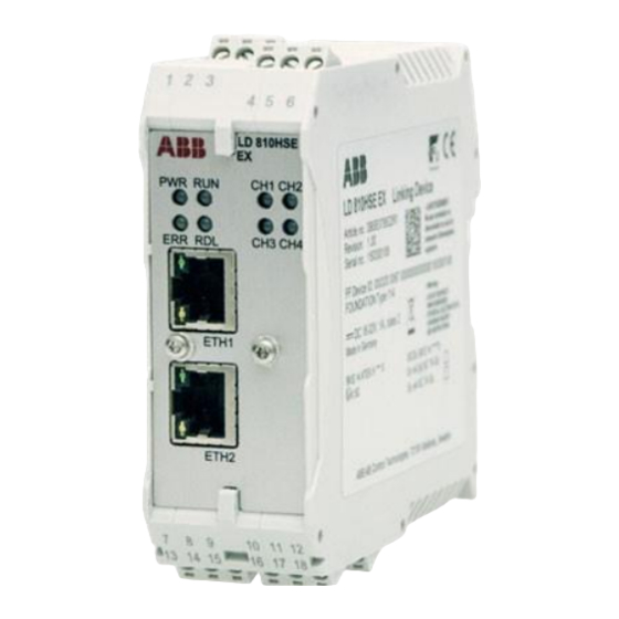
Page 37: Interfaces And Display Elements
2 Hardware Installation 2.5 Interfaces and Display Elements Interfaces and Display Elements Figure 2.5: LD 810HSE Ex 2.5.1 Status Indicators - LEDs The Linking Device is equipped with 8 LEDs on its front side: Figure 2.6: Status Indicators - LEDs 2PAA114135-610... - Page 38 2 Hardware Installation 2.5 Interfaces and Display Elements Table 2.13: Status Indicators - LEDs Item Description For details, refer to ... Power supply ... section Power Supply (PWR) LED Indicator on page 39 Running ... section LED Indicators in Stand-Alone Mode on page 40 Error Redundancy link...
- Page 39 2 Hardware Installation 2.5 Interfaces and Display Elements Table 2.14: Meanings of the LED Symbols (Continued) Symbol Color Lighting Green Flashing slowly (0.5 Hz) Green Flashing quickly (5 Hz) Power Supply (PWR) LED Indicator Table 2.15: Power Supply LED Indicator Symbol Color/Lighting Meaning...
- Page 40 2 Hardware Installation 2.5 Interfaces and Display Elements Table 2.16: LED Indicators in Stand-Alone Mode LEDs Meaning Start-up phase (approx. 7 seconds) During this phase, the redundancy role is determined. Non-redundant device, ready The device is operational; it is not part of a redundant set. Permanent hardware fault detection during startup A fatal error has been detected.
- Page 41 2 Hardware Installation 2.5 Interfaces and Display Elements Table 2.17: Power Supply LED Indicator Symbol Color/Lighting Meaning Flashing green Redundancy link communication is ok (triggered by redundancy link packets) Link communication interrupted or aborted (broken down) No link communication Table 2.18: LED Indicators in Redundant Mode LEDs Meaning Start-up phase (approx.
- Page 42 2 Hardware Installation 2.5 Interfaces and Display Elements Table 2.18: LED Indicators in Redundant Mode (Continued) LEDs Meaning Primary device or non-redundant device, hardware failure The device is acting as non-redundant device, but a minor hardware failure has been detected during start-up. In the case of a primary device in a redundant set, the secondary device is not ready.
- Page 43 2 Hardware Installation 2.5 Interfaces and Display Elements Table 2.18: LED Indicators in Redundant Mode (Continued) LEDs Meaning Secondary device, hardware failure The device is acting as secondary device in a redundant set, but a hardware failure has been detected. Details are available on the Diagnostics page of the web server of the Linking Device.
- Page 44 2 Hardware Installation 2.5 Interfaces and Display Elements Table 2.18: LED Indicators in Redundant Mode (Continued) LEDs Meaning Secondary with H1 error Primary, configuration error Status Indications of the 4 H1 Channels The following table shows the meanings of the 4 H1 channel LEDs (CH1 ... CH4): Table 2.19: LED Indicators of the 4 H1 Channels Symbol Color/lighting...
-
Page 45: Commissioning The Hardware
2 Hardware Installation 2.6 Commissioning the Hardware Table 2.19: LED Indicators of the 4 H1 Channels (Continued) Symbol Color/lighting Meaning Flashing red No token received H1 link unused Commissioning the Hardware For commissioning the hardware, perform the following steps: Connect the H1 links to the terminal blocks of the H1 interfaces. Since the Linking Device does not provide power to the H1 links, a power supply, a power conditioner, and a bus termination is required for each H1 link. -
Page 46: Replacing A Defective Linking Device In A Redundant Set Of Linking Devices
2 Hardware Installation 2.7 Replacing a Defective Linking Device in a Redundant Set of Linking Devices In a redundant set of Linking Devices, removing the power supply, the Ethernet cable or a H1 link cable from the primary device causes a redundancy change-over. Before doing so, make sure that the secondary device is operational (and not still booting due to a prior change-over) and the redundancy link interface cable is intact and connected. -
Page 47: Adding A Second Linking Device To Form A Redundant Set Of Linking Devices
2 Hardware Installation 2.8 Adding a Second Linking Device to Form a Redundant Set of Linking Devices Connect the Ethernet cable and the redundancy link wiring. Make sure that the redundancy link wiring is connected before plugging in the power terminal block. -
Page 48: Replacing A Ld 800 Hse Ex By A New Ld 810Hse Ex
2 Hardware Installation 2.9 Replacing a LD 800 HSE Ex by a New LD 810HSE Ex The second Linking Device will take over the configuration data from the primary device and will start operation in the role “Secondary”. For indication of proper operation as a secondary device, refer to Status Indicators - LEDs on page Configure the Linking Device redundancy with the configuration tool (Fieldbus Builder... - Page 49 2 Hardware Installation 2.9 Replacing a LD 800 HSE Ex by a New LD 810HSE Ex Connect the Ethernet cable and the redundancy link wiring. Make sure that the redundancy link wiring is connected before plugging in the power terminal block. If the new LD 810HSE Ex is powered while the redundancy link is missing, it will behave like an independent, non-redundant primary device.
- Page 50 2 Hardware Installation 2.9 Replacing a LD 800 HSE Ex by a New LD 810HSE Ex Plug in the power terminal block. The boot process and the download of the configuration information take about 1 minute. For indication of proper operation as a secondary device, refer to Status Indicators - LEDs on page Once the old LD 800HSE Ex is replaced by a new LD 810HSE Ex, the module name...
- Page 51 2 Hardware Installation 2.9 Replacing a LD 800 HSE Ex by a New LD 810HSE Ex In Fieldbus Builder FOUNDATION™ Fieldbus, identify and right-click the replaced LD800HSE and start the Linking device initialization and address assignment. Figure 2.8: Linking Device Initialization and Address Assignment in Fieldbus Builder FOUNDATION™...
- Page 52 2 Hardware Installation 2.9 Replacing a LD 800 HSE Ex by a New LD 810HSE Ex Make sure that the connected segment LEDs change from red to blinking green. 2PAA114135-610...
-
Page 53: Configuration
3 Configuration 3.1 Communication Settings Configuration Communication Settings Although the Linking Device is delivered with a pre-configured IP address (192.168.0.10), it must be assigned an IP address from your LAN address range. Furthermore, subnet mask and gateway IP address must be set accordingly. This information is referred to as IP configuration. -
Page 54: Setting Up An Ip Connection Between Pc And Linking Device
3 Configuration 3.1 Communication Settings Table 3.2 shows the possible configuration functions depending on the interface that is used. Those functions available via web browser (HTTPS protocol, recommended) is explained in detail in the following subsections. Table 3.2: Configuration Functions and Interfaces Type of connection protocol HTTPS Port of Linking Device to be used... - Page 55 3 Configuration 3.1 Communication Settings Step 2: Configure your PC in such a way that you have access to the network range from 192.168.0.1 to 192.168.0.254. For this purpose, you may have to assign your PC a second IP address (e. g. IP address 192.168.0.100, net mask = 255.255.255.0). For details refer to Assignment of a Second (Local) IP Address to the Service Computer on page...
- Page 56 3 Configuration 3.1 Communication Settings Assignment of a Second (Local) IP Address to the Service Computer This subsection describes how to assign a second IP address to a PC running on the latest supported operating system. For other operating systems, refer to the corresponding instruction manual or to the online help of the operating system used.
- Page 57 3 Configuration 3.1 Communication Settings • Right-click Local Area Connection, then click Properties. Figure 3.2: Local Area Connection Properties • Click the Internet Protocol (TCP/IP) checkbox, then click the Properties button. Figure 3.3: Internet Protocol (TCP/IP) Properties 2PAA114135-610...
- Page 58 3 Configuration 3.1 Communication Settings In the Internet Protocol (TCP/IP) Properties dialog, the regular (first) IP address, the subnet mask and the default gateway address are shown. To add a second IP address, click the Advanced... button. Figure 3.4: Advanced TCP/IP Settings •...
-
Page 59: System Settings
3 Configuration 3.2 System Settings • Confirm all dialog boxes with OK till you get back to the Local Area Connection Properties window. • Click the Close button. System Settings After an IP connection between PC and Linking Device has been set up as described in subsection Setting Up an IP Connection Between PC and Linking Device on page you may access the Linking Device from your PC by means of a web browser supporting... - Page 60 3 Configuration 3.2 System Settings Table 3.3 shows the list of default users who can log in to the Linking Device using the Linking Device web server page. Table 3.3: Users and Their Roles Default user Default Password Role operat vwit Operation user config...
- Page 61 3 Configuration 3.2 System Settings Figure 3.7: Default Password Page This caution message is displayed for all users until the password is changed. Click the Goto webpage button to continue. After logging in, the System Status page opens, see Figure 3.8.
- Page 62 3 Configuration 3.2 System Settings Table 3.5 shows the menus available from the LD 810HSE Ex web server: Table 3.5: Menu Structure of the Web Server Information Configuration Contact Sub menu System Status Network Configuration Contact System Diagnostics Firmware Update H1 Diagnostics Set Password Hardware Diagnostics...
- Page 63 3 Configuration 3.2 System Settings Figure 3.9: Network Configuration Page Enter the new IP configuration information. • The Host Name is not pre-configured. It is not used and may therefore be left empty. • IP Address and Subnet Mask must be present in any case. •...
- Page 64 3 Configuration 3.2 System Settings Figure 3.10: New Network Settings Page Do not access the web server of the Linking Device before the New Network Settings or Error Occured page is displayed in the browser window. If you do so, you will have to clear the cache of your web browser after the boot process has finished, and then re-establish a connection to the web server of the Linking Device.
- Page 65 3 Configuration 3.2 System Settings Figure 3.11: Firmware Update Page Do not disconnect the power from the Linking Device while firmware download or reboot are in progress. Wait at least 60 seconds after the Success message has shown up. This subsection explains the general mechanism of updating the firmware of a Linking Device.
- Page 66 3 Configuration 3.2 System Settings It is recommended to erase the configuration part of the flash memory by checking Erase Linking Device Configuration. This clears the FF configuration information (plant configuration), but the IP configuration is not changed. If you erase the Linking Device configuration, the password will be reset to its default value (config).
- Page 67 If the Linking Device configuration was erased, download the configuration data to the Linking Device. Downloading configuration data to a Linking Device requires two steps to be carried out in the ABB configuration tools: • initialization and address assignment of the Linking Device •...
- Page 68 3 Configuration 3.2 System Settings Identical Configuration File Formats. The following procedure works only if the configuration file format is the same for the old and new firmware release. The only impact on process operation is that caused by a redundancy switch-over. Check which Linking Device acts as secondary device.
- Page 69 Wait until both devices have completed rebooting. Download configuration data to the redundant set of devices. Downloading configuration data to a Linking Device requires the following steps to be carried out in the ABB configuration tools: • initialization and address assignment of the Linking Device •...
- Page 70 3 Configuration 3.2 System Settings Figure 3.13: Set Password Page Upload Certificates The LD 810HSE Ex is preconfigured with a self-signed certificate, which is usually not trusted by clients. To provide secure communication, you have to ensure secure connection, e. g. by connecting the LD 810HSE Ex directly to your PC and configuring the server certificate, private key file and necessary intermediate certificates.
-
Page 71: Plant Configuration And Commissioning
In general, the Linking Device will be used in a plant with H1 devices and HSE devices, all of which must be configured before commissioning. With 800xA - Device Management FOUNDATION™ Fieldbus, ABB provides the Fieldbus Builder FOUNDATION™ Fieldbus, a tool for the configuration and commissioning of FOUNDATION™ Fieldbus subsystems in the Industrial IT 800xA Plant Explorer. -
Page 72: Using A Redundant Set Of Linking Devices
LD 810HSE Ex Media CD-ROM or is available for download from myABB/My Control System. Additional information, firmware, and capabilities files for this product are available in the MyABB portal (https://myportal.abb.com/home). For details refer to section 2 Hardware Installation. -
Page 73: Speed Up Of Device Assignment
3 Configuration 3.3 Plant Configuration and Commissioning 3.3.3 Speed up of Device Assignment The time needed for an H1 device address assignment can be configured for dynamic adaption to the speed of the H1 device. Set parameter “T3” of an individual H1 link as follows: •... - Page 74 2PAA114135-610...
-
Page 75: Built-In Web Server
4 Built-in Web Server Built-in Web Server General information about the Linking Device can be queried via the web pages of the built-in web server, refer to Logging in to the Web Server Interface on page 59. This requires a standard web browser supporting JavaScript (e. g. Microsoft Internet Explorer) on a PC that is connected to the Linking Device via Ethernet, refer to Setting Up an IP Connection Between PC and Linking Device on page... -
Page 76: System Status
4 Built-in Web Server 4.1 System Status The Contact page as shown in Figure 4.1 provides useful information in the case that • require general information about the product or • need technical support • need to provide feedback about the product Figure 4.1: Contact Page System Status Figure 4.2... - Page 77 Unique device identifier with 22 characters as shown in Figure 4.2: • starting with the manufacturer identifier (string 000320 in the screenshot above for ABB) • followed by the device type (string 0067 in the screenshot above for LD 810HSE Ex) •...
-
Page 78: System Diagnostics
4 Built-in Web Server 4.2 System Diagnostics Table 4.1: System Status (Continued) IP Address IP address of the redundant Linking Device; this is empty, if the (redundant Device) Linking Device operates in non-redundant mode. Subnet Mask IP subnet mask Default Gateway Address of the IP gateway to other subnets Operating State Current operating state of the Linking Device;... - Page 79 4 Built-in Web Server 4.2 System Diagnostics Figure 4.3: System Diagnostics Page This page indicates system diagnostics information of the Linking Device as explained Table 4.2. Table 4.2: System Diagnostics System Uptime Elapsed time since the LD 810HSE Ex has been booted as well as date and time when the system was started.
-
Page 80: H1 Diagnostics
4 Built-in Web Server 4.3 H1 Diagnostics Table 4.2: System Diagnostics (Continued) Date Current date and time HSE Frame Statistics Total number and number per second of HSE frames grouped into categories such as Publisher/Subscriber, ReportDistribution, ClientServer, SystemManagement and Redundancy Synchronization (not supported by AssetMonitor Linking Device). -
Page 81: Hardware Diagnostics
4 Built-in Web Server 4.4 Hardware Diagnostics • Shielding problems • Termination problems • Crosstalk from adjacent cables Besides useful diagnostics during commissioning, this information can also be used to detect deteriorating wiring conditions in the plant before the process is affected. Table 4.3: H1 Diagnostics Framing Errors Total number of framing errors on the H1 channel since last reboot... -
Page 82: Version Information
4 Built-in Web Server 4.5 Version Information Figure 4.5: Hardware Diagnostics Page Version Information The Linking Device consists of an LD Base Module (motherboard) and an H1 Module (daughterboard) with the 4 H1 channels. Both modules as well as the entire device are identified by hardware version numbers and serial numbers. -
Page 83: Linking Device Web Server Diagnostics
4 Built-in Web Server 4.6 Linking Device Web Server Diagnostics Figure 4.6: Version Information Page Linking Device Web Server Diagnostics Figure 4.7 shows the Diagnostics page when the user is logged in as diag. 2PAA114135-610... - Page 84 4 Built-in Web Server 4.6 Linking Device Web Server Diagnostics Figure 4.7: Diagnostics Page in Diag User Mode Click Read log files. The following Redundancy Switch Log page appears as shown in Figure 4.8. 2PAA114135-610...
-
Page 85: Clearing The Log Files
4 Built-in Web Server 4.6 Linking Device Web Server Diagnostics Figure 4.8: Redundancy Switch Log Page For support, save this log files and send them for analysis to the service organization. 4.6.1 Clearing the Log Files To clear the log file, click the back button of the browser window. Then click Clear log files. -
Page 86: Configuring The Syslog Server
4 Built-in Web Server 4.6 Linking Device Web Server Diagnostics The contents of the log files are cleared as shown in Figure 4.10. Figure 4.10: Log Cleared Page 4.6.2 Configuring the Syslog Server Click Enable Trace via Syslog on the indexdebug.html page. The following page appears as shown in Figure 4.11. -
Page 87: Statistic Information
4 Built-in Web Server 4.6 Linking Device Web Server Diagnostics 4.6.3 Statistic Information Detailed statistic information for each channel (LAS Frame, Livelist, Communication Relationship List (CRL), Queued User-Triggered Bidirectional (QUB), and Buffered Network-Triggered Unidirectional Statistic (BNU)) is available. Figure 4.12: Statistics Information Page 2PAA114135-610... - Page 88 4 Built-in Web Server 4.6 Linking Device Web Server Diagnostics In the Statistic Information table, click Read to see the detailed statistics of each channel. Click Clear to delete the statistics of the corresponding channel. Clear the statistics counter only if it is requested by the service organization. To clear all statistics at one time, click Clear all Statistic Counter.
- Page 89 4 Built-in Web Server 4.6 Linking Device Web Server Diagnostics Figure 4.13: Statistics Information Page Displaying the Thread Monitor To display the thread monitor, click Threads on the Statistics Information Page. 2PAA114135-610...
- Page 90 4 Built-in Web Server 4.6 Linking Device Web Server Diagnostics Figure 4.14: Statistics Information Page Displaying Information on Interrupt Resources To display interrupt resources, click Interrupts on the Statistics Information Page. 2PAA114135-610...
- Page 91 4 Built-in Web Server 4.6 Linking Device Web Server Diagnostics Figure 4.15: Statistics Information Page Displaying Network Statistics To display network statistics, click Network on the Statistics Information Page. Figure 4.16: Statistics Information Page Displaying Information on the File System To display file system, click Filesystem on the Statistics Information Page.
-
Page 92: Internal Device Information
4 Built-in Web Server 4.6 Linking Device Web Server Diagnostics Figure 4.17: Statistics Information Page 4.6.4 Internal Device Information These options are for service personnel only. 2PAA114135-610... -
Page 93: Appendix A Limits And Performance Data
4*16 client/server connections can be used in parallel. For the availability with other system environments, check the corresponding system release notes. In ABB system environments, the configuration tools Fieldbus Builder FOUNDATION™ Fieldbus and Control Builder F will take these limits into account automatically depending on the capability of the system version and if not noted otherwise. -
Page 94: Limits Per H1 Channel
Note, that the total size of the LAS schedule domain must not exceed 2000 octets. Additionally for each component of the LAS schedule, the maximum value given in the table applies. The ABB configuration tools Fieldbus Builder FOUNDATION™ Fieldbus and Control Builder F will automatically take into account these limits. A.2.2... -
Page 95: H1 Slot Time
A Limits and Performance Data A.3 Duration of Redundancy Switch-Over A.2.3 H1 Slot Time The H1 bus parameter SlotTime has to be less than 50. Otherwise, the maximum time of inactivity on an H1 link would exceed 200 ms, which in turn would have an impact on the fault detection time, i. -
Page 96: Device Redundancy
A Limits and Performance Data A.4 Device Redundancy Device Redundancy The following fault conditions cannot be detected in the Linking Device itself and need to be covered at application level: • a loss of an H1 connection between the primary device and a subset of devices on an H1 link •... -
Page 97: Appendix B Technical Reference
B Technical Reference B.1 Supported HSE Services Appendix B Technical Reference Supported HSE Services • Open Session • Close Session • FMS Initiate • FMS Abort • FMS Read • FMS Read with Subindex • FMS Write • FMS Write with Subindex •... -
Page 98: Supported H1 Services
B Technical Reference B.2 Supported H1 Services • FMS Resume • FMS Reset • FMS Kill • SM Identify • SM Find Tag Query • SM Find Tag Reply • SM Clear Address • SM Set Assignment Info • SM Clear Assignment Info •... -
Page 99: Hse Object Dictionary
B Technical Reference B.3 HSE Object Dictionary • FMS Start • FMS Stop • FMS Resume • FMS Reset • FMS Kill • SM Identify • SM Find Tag Query • SM Find Tag Reply • SM Clear Address • SM Set Address •... -
Page 100: Technical Reference
B Technical Reference B.3 HSE Object Dictionary Object Index Schedule Activation Variable Schedule List Characteristics NM Characteristics Record Configured Session List Header Record Configured Session Record 277 - 340 Automatic Session List Header Record Automatic Session Record 342 - 373 Session Statistics List Header Record Session Statistics Record 375 - 378... -
Page 101: H1 Interface Object Dictionary
B Technical Reference B.4 H1 Interface Object Dictionary H1 Interface Object Dictionary Object Index H1 SM Directory H1 NM Directory SM Support Current Time Local Time Diff Ap Clock Sync Interval Time Last RCVD Primary Ap Time Publisher Time Publisher Addr Macrocycle Duration Dev Id Pd Tag... - Page 102 B Technical Reference B.4 H1 Interface Object Dictionary Object Index Dlme Basic Characteristics Record Dlme Basic Info Record Dlme Basic Statistics Record not supported Dlme Link Master Capabilities Variable Dlme Link Master Info Record Primary Link Master Flag Variable Live List Status Array Variable Max Token Hold Time Array (access via ReadWithSubindex or...
-
Page 103: Data Format For Schedule Domain
B Technical Reference B.5 Data Format for Schedule Domain Data Format for Schedule Domain The format for the data of a schedule domain is described in IEC 61158-4:2014 Data Link Layer Protocol Specification. A schedule domain consists of the schedule summary and n sub-schedules. -
Page 104: Sequence
B Technical Reference B.5 Data Format for Schedule Domain Meaning Range of values Octets schedule version 1 - 0xffff subschema identifier 1 - 0xffff period 1 - 0xffffffff sequence 1 sequence i sequence m end of sub-schedule 4 * l, I = 1, 2, 3, ... B.5.3 Sequence Meaning... -
Page 105: Redundancy
B Technical Reference B.6 Redundancy Redundancy FOUNDATION™ fieldbus is also a distributed control architecture that provides increased availability compared to centralized control architectures. But as a Linking Device acts as gateway between H1 links and the HSE subnet, it represents a bottleneck concerning the availability of communication paths leading from HSE to H1 and vice versa. -
Page 106: Fault Domain
B Technical Reference B.6 Redundancy The secondary device acts as Backup Link Master on each H1 link attempting to take over the LAS role if required. Additional Link Master devices may be configured to act as Backup Link Master on the H1 links. The two devices forming a redundant set communicate via a redundancy link interface and via Ethernet. - Page 107 B Technical Reference B.6 Redundancy • a failure in the Ethernet communication between the two Linking Devices (3) • a loss of an H1 connection between the primary device and the entire H1 link; this may be caused by disconnecting an H1 cable from the primary device (4) if Linking Device 1 acts as primary device or (5) if Linking Device 2 acts as primary device) Detecting a loss of an H1 connection between the primary device and the entire H1 link requires that at least two H1 devices have been connected to that H1 channel of...
-
Page 108: Redundancy Behavior
B Technical Reference B.6 Redundancy Take Over of Primary Role The secondary device takes over the primary role The serial connection to the primary device is lost. It acts as Link Active Scheduler on all configured H1 links. Its Ethernet port is operational. Restoring Redundancy Only one of the listed faults may be present at a time. - Page 109 B Technical Reference B.6 Redundancy Table B.2: Redundancy Behavior Fault Fault Condition Fault Detection Effect Repair Measures Treatment Primary device Device fails completely or Primary role Redundancy Transient fault: fails due to actively switch-over. Automatic reboot software watchdog expires transferred to System •...
- Page 110 B Technical Reference B.6 Redundancy Table B.2: Redundancy Behavior (Continued) Fault Fault Condition Fault Detection Effect Repair Measures Treatment Secondary device Device fails completely or Secondary System Transient fault: fails due to device degrades to Automatic reboot • software watchdog assumes and non-redundant •...
- Page 111 B Technical Reference B.6 Redundancy Table B.2: Redundancy Behavior (Continued) Fault Fault Condition Fault Detection Effect Repair Measures Treatment TCP connection Time-out on TCP Secondary System Repair Ethernet lost between connection. device degrades to connection. primary device and assumes and non-redundant Detection time less than Secondary device...
- Page 112 2PAA114135-610...
-
Page 113: Appendix C Linking Device For Zone 2 Explosion And Protection Environment
C Linking Device for Zone 2 Explosion and Protection Environment C.1 General Requirements Appendix C Linking Device for Zone 2 Explosion and Protection Environment This section is an extension for the LD 810HSE Ex hardware installation and only refers to aspects that are relevant for explosion protection in a Zone 2 environment. To ensure personal safety and implementation of the functionality of the device, this instruction manual must be read thoroughly before installing the Linking Device. -
Page 114: Commissioning And Installation
C Linking Device for Zone 2 Explosion and Protection Environment C.2 Commissioning and Installation • Electrostatic aspects must be considered when mounting the bus-modules. • The hazard of any objects falling onto the bus-module must be prevented. • If the Linking Device does not meet the requirements of impact protection, protection against impact energy and IP protection must be provided at the place of use as per the requirements stated in section 26.4 of IEC/EN 60079-0. - Page 115 C Linking Device for Zone 2 Explosion and Protection Environment C.2 Commissioning and Installation • The equipment must be protected against accidental opening. The follwoing warning sign must be installed near the plugs: Warning: Do not separate when energized! • The connecting plugs must be secured using a torque of min.
-
Page 116: Linking Device Usage
C Linking Device for Zone 2 Explosion and Protection Environment C.3 Linking Device Usage Linking Device Usage The Linking Device is only approved for intended and appropriate use. In case of non-compliance, the warranty and manufacturer's liability does not apply. •... - Page 117 C Linking Device for Zone 2 Explosion and Protection Environment C.4 Maintenance and Repair Visual inspection: defines an inspection that identifies, without the use of access equipment and tools, those defects, such as missing bolts, that will be apparent to the eye.
- Page 118 2PAA114135-610...
- Page 119 D Declarations by the Manufacturer Appendix D Declarations by the Manufacturer This device complies with the requirements of the EC directive 2014/30/EU, "Electromagnetic Compatibility" (EMC directive) and meets the following requirements: Emission: • EN 55011 Industrial, scientific and medical (ISM) devices - radio disturbance - limits and methods of measurement •...
- Page 120 D Declarations by the Manufacturer Electrical and electronic equipment must be disposed of separately from normal waste at the end of its operational lifetime. Packaging material and worn components shall be disposed of according to the regulations applicable in the country of installation. This is a Class A product.
- Page 121 E Glossary Appendix E Glossary Application Process Compel Data Cyclic Redundancy Check Device Description DHCP Dynamic Host Configuration Protocol DLCEP Data Link Connection Endpoint Function Block FBAP Function Block Application Process Field Device Access FOUNDATION™ Fieldbus Fieldbus Message Specification Bus System High Speed Ethernet Identifier Internet Protocol...
- Page 122 E Glossary Object Dictionary Physical Device Random Access Memory System Management SMIB System Management Information Base System Management Kernel SMKP System Management Kernel Protocol SNMP Simple Network Management Protocol SNTP Simple Network Time Protocol Transmit Control Protocol TFTP Trivial File Transfer Protocol User Datagram Protocol Virtual Communication Relationship Virtual Field Device...
- Page 124 800xA is a registered or pending trademark We reserve all rights to this document www.abb.com/800xA of ABB All rights to other trademarks reside and the items and images it contains www.abb.com/controlsystems with their respective owners The reproduction, disclosure to third parties...
Need help?
Do you have a question about the Ability 800xA Series and is the answer not in the manual?
Questions and answers