Page 1
Instructions-Parts 
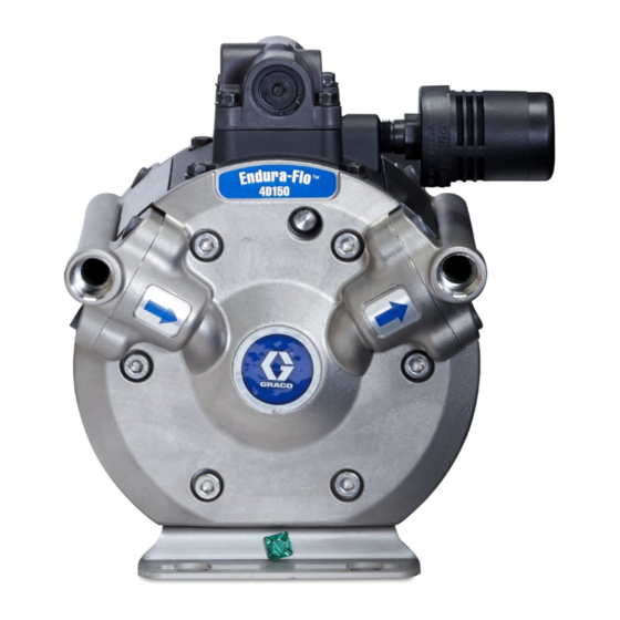
Endura-Flo™ 4D150 and 4D350 333015E Diaphragm Pump Used to pump waterborne and solvent-based paints and catalysts. For professional use only. Important Safety Instructions Read all warnings and instructions in this manual. Save these instructions. See page 3 for model information, including maximum pressures and approvals.
Models Models All models have the following maximum pressures. See Performance Charts, page 36, for actual working pressures and flow rates. • 100 psi (0.7 MPa, 7 bar) Maximum Air Input Pressure • 400 psi (2.8 MPa, 28 bar) Maximum Fluid Working Pressure •...
Warnings Warnings The following warnings are for the setup, use, grounding, maintenance, and repair of this equipment. The exclamation point symbol alerts you to a general warning and the hazard symbols refer to procedure-specific risks. When these symbols appear in the body of this manual or on warning labels, refer back to these Warnings.
Page 5
Warnings WARNING EQUIPMENT MISUSE HAZARD Misuse can cause death or serious injury. • Do not operate the unit when fatigued or under the influence of drugs or alcohol. • Do not exceed the maximum working pressure or temperature rating of the lowest rated system component.
It is not an actual system design. Contact your Graco distributor for assistance in designing a system to suit your particular needs. • Always use Genuine Graco Parts and Accessories, available from your Graco distributor. If you supply your own accessories, be sure they are adequately sized and pressure-rated for your system.
Installation Air Line 1. Install the air line accessories as shown in Typical Installation, page 8. Use adaptors as needed. Be sure the air line supplying the accessories is grounded. a. The fluid pressure can be controlled with either an air regulator (F) to control the air into the pump, or with a fluid regulator (H) to control the fluid out of the pump.
Installation Fluid Suction Line • See Technical Specifications, page 40, to determine the fluid inlet size of your pump. A fluid drain (J) valve is required in your system • For maximum suction lift (wet and dry) information, to relieve pressure in the hose if it is plugged. Technical Specifications, page The drain valve reduces the risk of serious injury, 1.
Page 10
Installation Typical Installation The pump is sold separately from all accessories. Filters, regulators, fittings, hoses, etc., are shown here to depict one possible system setup. 333015E...
Page 11
Installation Pump Pump fluid inlet Bleed-type master air valve (required) Fluid hose Air supply line Gun air hose Air line filter Spray gun Air line shutoff valve Pump air inlet Pump air regulator Agitator Gun air regulator Ground wire Fluid pressure regulator Fluid filter Drain/circulation valve Fluid circulation line...
Installation Grounding Fluid supply drum: • Follow your local code. All fluid pails used when flushing: • Follow your local code. Use only conductive metal pails placed on a grounded surface. Do not place the pail on a nonconductive surface, such as paper The equipment must be grounded to reduce the or cardboard, which interrupts the grounding risk of static sparking.
Operation Operation Start and Adjust the Pump Pressure Relief Procedure 1. Be sure the pump is properly grounded. Refer Follow the Pressure Relief Procedure Grounding, page whenever you see this symbol. 2. Check all fittings to be sure they are tight. Be sure to use a compatible liquid thread sealant on all male threads.
Do not over-lubricate the pump. Oil is exhausted you are unsure how to completely flush your system, through the muffler and could contaminate your contact your Graco distributor. fluid supply or other equipment. Excessive lubrication can also cause the pump to malfunction.
Troubleshooting Troubleshooting • Follow the Pressure Relief Procedure, page before checking or servicing the equipment. • Check all possible problems and causes before disassembly. Problem Cause Solution Replace. Pump cycles at stall or fails to hold The check valve cartridges (9) are pressure at stall.
Page 16
Troubleshooting Problem Cause Solution Air escapes continually from the Air valve cup (112) is damaged. Replace damaged parts. muffler. Foreign matter is inside the pump. Check air filter. Shaft seals (26) are worn. Replace. Pump does not start, or pressure Check valve cartridges (9) are worn.
Repair/Service Repair/Service Repair or Replace the Air Valve 4. Remove screws (17). Remove the air valve (1) and the gasket (13). 5. To repair the air valve, go to Replace Seals or Rebuild Air Valve, page 18, in next section. 6.
Page 18
Repair/Service Replace Seals or Rebuild Air Valve Reassemble the Air Valve NOTE: Apply lithium-based grease whenever Repair Kits, page 35, to find the correct repair instructed to grease. kits for your pump. Parts in Air Valve Seal Kits are marked †. Parts in Air Valve Repair Kits are marked 1.
Page 19
Repair/Service Air Valve Disassembly or Reassembly Apply lithium-based grease. U-cup lips must face piston. 333015E...
313840. assembly. Use only an approved replacement battery, and an approved fuse (see DataTrak manual). Use of an unapproved battery or fuse will void Graco’s warranty and Ex approvals. 333015E...
Repair/Service Disassemble the Fluid Section 3. Remove the check valve cartridges (9). 4. Do not remove the manifold o-rings (38) yet. 5. Use a hex socket wrench (6 mm for 4D150 models; 8 mm for 4D350 models) to remove the bolts (15) from one fluid cover (4).
Page 22
Repair/Service 6. Your replacement diaphragm kit includes two 11. Leave the air on. Use a 3/4 in. claw foot wrench diaphragm tools (AC) and a plug (AD). These to loosen the piston shaft (24) attached to the parts are used to provide an air-assist to make it other diaphragm.
Repair/Service Disassemble the Center Section 1. Use a 10 mm socket wrench to remove the four 6. Pull the piston (20) out of the cylinder (27). bolts (17), then remove the air manifold (6). If Remove the o-ring (28) from the piston. the air valve (1) doesn’t need service, leave it 7.
Repair/Service Reassemble the Center Section 1. Lubricate and install a u-cup (26) in each air 4. The piston assembly should still be one piece. If cover (7). U-cup lips must face out of center the two shafts came apart during disassembly, housing.
Page 25
Repair/Service 5. Lubricate and install the large o-ring (28) on the 8. Align the second air cover (7) and press it down outside of the piston. over the cylinder and piston. Use a 13 mm socket wrench to tighten the bolts on each air cover. 6.
Repair/Service Reassemble the Fluid Section 10. Use four bolts (17) to attach the mounting base (5) to the pump. It can be parallel to or perpendicular to the length of the pump. Torque Follow all notes in the illustrations. These notes the bolts to 100–120 in-lb (11–14 N•m).
Page 27
Repair/Service 4. Align and attach the fluid cover to lock the 5. Supply shop air at about 20 psi (0.14 MPa, diaphragm in place. NOTE: You must use 1.4 bar). Do not use over 30 psi (0.21 MPa, the fluid cover that has the install tools (AC) 2.1 bar).
Page 28
Repair/Service Install the Fluid Manifolds 1. Install new o-rings (38) on the two inlet and two 3. The manifolds are identical, but it is likely that outlet ports. the inlet and outlet manifold will have different fittings. Install the inlet manifold (2) on the 2.
Torque Instructions Torque Instructions 2. Repeat for fluid manifolds. Torque to: 4D150 Models: 20–25 ft-lb (27–34 N∙m) 4D350 Models: 28–33 ft-lb (38–45 N∙m) If fluid cover or manifold fasteners have been 3. Retorque the air valve and air valve manifold loosened, it is important to torque them using the fasteners in a crisscross pattern to 100–120 in-lb following procedure to improve sealing.
Page 31
Parts 4D150 Models Part Description Part Description — — — SCREW, hex flange, VALVE, air; small; 17 includes gasket (ref. 13) M6–1.0 x 20 mm; also and screws (ref. 17) included with air valve (ref. 1), mounting 17H318 Smart (for use with bracket (ref.
Page 32
Parts 4D350 Models Part Description Part Description VALVE, air; small; 17H303 DIAPHRAGM, includes gasket (ref. 13) overmolded, kit; and screws (ref. 17) includes 2 diaphragms, diaphragm replacement 17H316 Smart (for use with tools, and Ref. 38 DataTrak) 20 17H310 PISTON ASSEMBLY; 17H317 Standard kit;...
Technical Specifications Technical Specifications Metric Maximum air input pressure 100 psi 7 bar, 0.7 MPa 70 psi 4.8 bar, 0.48 MPa Maximum inlet feed pressure* Maximum fluid working pressure 400 psi 28 bar, 2.8 MPa Maximum static fluid pressure 430 psi 30 bar, 3.0 MPa Ratio Maximum recommended continuous...
Page 41
Technical Specifications Noise Data Average Sound Pressure Levels in dBA at 20 cpm (measured at 1 meter (3.28 ft) horizontal, 1.5 meter (4.9 ft) above the equipment) At 70 psi (0.5 MPa, 5.0 bar) 4D150 62.3 dBA 4D350 65.1 dBA At 100 psi (0.7 MPa, 7.0 bar) 4D150 62.9 dBA...
With the exception of any special, extended, or limited warranty published by Graco, Graco will, for a period of twelve months from the date of sale, repair or replace any part of the equipment determined by Graco to be defective.
Need help?
Do you have a question about the Endura-Flo 4D150 and is the answer not in the manual?
Questions and answers