Tektronix MDO34 Installation And Safety Manual
Mixed domain oscilloscope
Hide thumbs
Also See for MDO34:
- Declassification and security instructions (24 pages) ,
- Printable help (282 pages) ,
- Quick start manual (39 pages)
Table of Contents
Advertisement
ООО "Техэнком"
Контрольно-измерительные приборы и оборудование
www.tehencom.com
3 Series MDO
Mixed Domain Oscilloscope
Installation and Safety Manual
Warning
The servicing instructions are for use by qualified personnel only. To avoid
personal injury, do not perform any servicing unless you are qualified to do
so. Refer to all safety summaries prior to performing service.
Supports 3 Series MDO Product Firmware V1.1 and above
www.tek.com
071-3608-00
Advertisement
Table of Contents

Related Manuals for Tektronix MDO34


Summary of Contents for Tektronix MDO34
- Page 1 ООО "Техэнком" Контрольно-измерительные приборы и оборудование www.tehencom.com 3 Series MDO Mixed Domain Oscilloscope Installation and Safety Manual Warning The servicing instructions are for use by qualified personnel only. To avoid personal injury, do not perform any servicing unless you are qualified to do so.
- Page 2 Tektronix. All rights reserved. Licensed software products are owned by Tektronix or its subsidiaries or suppliers, and are protected by national copyright laws and international treaty provisions. Tektronix products are covered by U.S. and foreign patents, issued and pending. Information in this publication supersedes that in all previously published material. Specifications and price change privileges reserved.
-
Page 3: Table Of Contents
Identifying items in the time domain display ....................Identifying items in the frequency domain display ..................Badges ................................. Configuration menus ............................ Zoom user interface elements ........................Using the touchscreen interface for common tasks ..................MDO32, MDO34 Installation and Safety Manual... - Page 4 Run Signal Path Compensation (SPC) ......................Compensate TPP0250, TPP0500B, or TPP1000 probes ................Connect to a network (LAN) ......................... EMC safety and environmental compliance Compliance information ..........................EMC compliance ............................ Safety compliance ..........................Environmental compliance ........................MDO32, MDO34 Installation and Safety Manual...
-
Page 5: Important Safety Information
Connect and disconnect properly. Do not connect or disconnect probes or test leads while they are connected to a voltage source. Use only insulated voltage probes, test leads, and adapters supplied with the product, or indicated by Tektronix to be suitable for the product. - Page 6 Be sure your work area meets applicable ergonomic standards. Consult with an ergonomics professional to avoid stress injuries. Use only the Tektronix rackmount hardware specified for this product. Probes and test leads Before connecting probes or test leads, connect the power cord from the power connector to a properly grounded power outlet.
-
Page 7: Service Safety Summary
Use care when servicing with power on. Dangerous voltages or currents may exist in this product. Disconnect power, remove battery (if applicable), and disconnect test leads before removing protective panels, soldering, or replacing components. Verify safety after repair. Always recheck ground continuity and mains dielectric strength after performing a repair. MDO32, MDO34 Installation and Safety Manual... -
Page 8: Terms In The Manual
(This symbol may also be used to refer the user to ratings in the manual.) The following symbols may appear on the product: MDO32, MDO34 Installation and Safety Manual... -
Page 9: Preface
■ User interface optimized for touchscreen use ■ Sample rates of 2.5 GS/s on all analog channels (5 GS/s on 1 or 2 channels for the MDO34 or MDO32 with the 1 GHz ■ option) 10 M points record length on all channels ■... -
Page 10: Related Documents
To learn about Use this document How to use instrument 3 Series MDO (MDO34, MDO32) Installation and Safety Manual (This document, Tektronix part functions number 071-3608-xx); standard accessory with the instrument. Single document with English, Japanese, and Simplified Chinese languages. -
Page 11: Installing Your Instrument
Installing your instrument Check shipped accessories Make sure that you received everything you ordered. If anything is missing, contact Tektronix Customer Support. In North America, call 1-800-833-9200. Worldwide, visit www.tek.com to find contacts in your area. Check the packing list that came with your instrument to verify that you have received all standard accessories and ordered items. -
Page 12: Operating Requirements
Max no damage +33 dBm (2 W) CW Peak Pulse Power: +45 dBm (32 W) Peak Pulse Power defined as <10 μs pulse width, <1% duty cycle, and reference level of ≥ +10 dBm MDO32, MDO34 Installation and Safety Manual... -
Page 13: Secure (Lock) The Oscilloscope
Lock an oscilloscope to a test bench or equipment rack to prevent property loss. Attach a standard laptop security lock to the rear panel of the oscilloscope, to secure the oscilloscope to a workbench, rack, or other location. MDO32, MDO34 Installation and Safety Manual... -
Page 14: Powering The Oscilloscope
Push the front panel power button to power the instrument on and off. The power button color indicates instrument power states: Unlit – no AC power applied Yellow – standby mode Blue – powered on To completely remove power from the instrument, disconnect the power cord. MDO32, MDO34 Installation and Safety Manual... -
Page 15: Check That The Oscilloscope Passes Power-On Self Tests
If one or more power-on self tests shows Failed: Power cycle the oscilloscope. Tap Utility > Self Test. If one or more power-on self tests still shows Failed, contact Tektronix Customer Support. Connecting probes Probes and cables connect the oscilloscope to your device under test (DUT). Use a probe that best matches your signal measurement needs. -
Page 16: Rackmount Information
The optional RM3 Rackmount Kit lets you install the oscilloscope in standard equipment racks. The rack mount requires six rack units (6U) of space to install. Contact Tektronix Customer Support to purchase the rackmount kit option RM3. Follow the instructions that come with the rackmount kit (RM3 Rackmount Kit Instructions, Tektronix part number 071-3609-xx). -
Page 17: Remote Access From A Web Browser
Use a swab to clean narrow spaces around controls and connectors. Do not use any liquid cleaning agents or chemicals that could damage the touchscreen, case, controls, markings or labels, or possibly infiltrate the case. MDO32, MDO34 Installation and Safety Manual... - Page 18 ООО "Техэнком" Контрольно-измерительные приборы и оборудование www.tehencom.com Installing your instrument MDO32, MDO34 Installation and Safety Manual...
-
Page 19: Getting Acquainted With Your Instrument
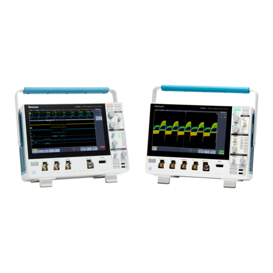
The front panel controls provide direct access to key instrument settings such as vertical, horizontal, trigger, and cursors. The connectors are where you input signals with probes or cables or insert USB devices. Figure 3: 3 Series MDO controls MDO32, MDO34 Installation and Safety Manual... - Page 20 Push a Multipurpose knob to enable the Fine mode for making smaller increment changes. Push the knob again to exit Fine mode. NOTE. If you have a mouse attached, pressing the mouse wheel toggles between Coarse and Fine adjustments. MDO32, MDO34 Installation and Safety Manual...
- Page 21 Normal trigger mode sets the instrument to acquire and display a waveform only when there is a valid trigger ■ event. If no trigger occurs, the last waveform record acquired remains on the display. If no last waveform exists, no waveform is displayed. MDO32, MDO34 Installation and Safety Manual...
- Page 22 If only one Bus waveform is displayed, pushing the button turns off the Bus waveform (removes it from Waveform ■ view). ■ If two Bus waveforms are displayed, pushing the button cycles through selecting each Bus waveform. MDO32, MDO34 Installation and Safety Manual...
- Page 23 Default Setup restores the oscilloscope settings (horizontal, vertical, scale, position, and so on) to the default settings. Default Setup does not change items found in the User Preferences menu. ■ Autoset automatically displays a stable waveform. MDO32, MDO34 Installation and Safety Manual...
- Page 24 USB ports are located at the lower right corner of the front panel and on the rear panel. Connect USB flash drives to which you can save or recall data (such as instrument software updates, waveforms, settings, and screen captures) or connect peripheral devices such as a mouse or keyboard. MDO32, MDO34 Installation and Safety Manual...
-
Page 25: Rear Panel Connections
AFG output. Power cord connector. Use only the power cord specified for this product and certified for the country of use. AFG Out is the signal output for the optional Arbitrary Function Generator (AFG) feature. MDO32, MDO34 Installation and Safety Manual... -
Page 26: The User Interface Screen
The Waveform View area displays analog, digital, math, reference, and bus waveforms. The waveforms include waveform handles (identifiers), trigger position, and level(s) indicators. See Identifying items in the time domain display on page 17. MDO32, MDO34 Installation and Safety Manual... -
Page 27: Identifying Items In The Time Domain Display
Configuration menus Identifying items in the time domain display Each area of the user interface has a specific function that helps manage information or controls. This topic shows and describes the key user interface elements. MDO32, MDO34 Installation and Safety Manual... - Page 28 The Results Bar Handle opens or closes the Results bar to maximize waveform screen viewing when needed. To reopen the Results bar, either tap the handle icon or swipe left from the right side of the display. MDO32, MDO34 Installation and Safety Manual...
- Page 29 Dragging a digital signal handle over another handle swaps location of the signals in the waveform view. Dragging a digital signal handle out of the group, creates a new group. A selected digital group or signal handle can be moved using the Vertical Position control. MDO32, MDO34 Installation and Safety Manual...
-
Page 30: Identifying Items In The Frequency Domain Display
Each area of the user interface has a specific function that helps manage information or controls. Vertical graticule labels Start frequency Reference level Vertical scale Center frequency Span and resolution bandwidth Stop frequency Reference marker MDO32, MDO34 Installation and Safety Manual... - Page 31 13. Average trace: Data from the Normal trace is averaged over multiple acquisitions. This is true power averaging, which occurs before the log conversion. Each power of 2 averaging reduces the displayed noise by 3 dB. MDO32, MDO34 Installation and Safety Manual...
-
Page 32: Badges
Result badges are located in the Results Bar. They show measurement or search results. The badge title also shows the measurement source or sources. To add a Measurement badge, tap the Measure button, select a measurement, and tap Add. Double-tap a Measurement badge to open its configuration menu to change or refine settings. MDO32, MDO34 Installation and Safety Manual... - Page 33 The instrument marks the waveform where those events occur with small down-pointing triangles along the top of the waveform graticule. Double-tap a search badge to open its configuration menu to change or refine search settings. MDO32, MDO34 Installation and Safety Manual...
- Page 34 To close the clipping message, change the vertical scale to show the entire waveform, disconnect the probe tip from the excessive voltage source, and check that you are probing the correct signal using the correct probe. MDO32, MDO34 Installation and Safety Manual...
- Page 35 Double-tap a System badge to open its configuration menu. The Horizontal badge also has Scale buttons, shown by single-tapping the badge. Use the Horizontal Scale buttons to increase or decrease the horizontal time/div setting. MDO32, MDO34 Installation and Safety Manual...
- Page 36 Configuration menu with access to all settings for the badge. Touch and hold Right-click menu with single tap access to common actions. Typical actions include turning off a channel and deleting a measurement or search badge. MDO32, MDO34 Installation and Safety Manual...
-
Page 37: Configuration Menus
Related settings are grouped into 'panels.' Tap the panel name to show those settings. Changes to panel settings can change the values and/or fields shown in that panel and other panels. Tap anywhere outside a configuration menu to close it. MDO32, MDO34 Installation and Safety Manual... -
Page 38: Zoom User Interface Elements
NOTE. Pinch, expand, and drag gestures in the Zoom View only change zoom magnification settings and Zoom Box position. Use the Zoom Title Bar controls to adjust the horizontal size of the zoom area. Click or tap the + or - buttons. MDO32, MDO34 Installation and Safety Manual... -
Page 39: Using The Touchscreen Interface For Common Tasks
Click and drag the Results Bar divider. Not all measurement or search badges display navigation buttons. Some dialog boxes will not close until you click an OK, Close, or other button in the dialog. MDO32, MDO34 Installation and Safety Manual... - Page 40 ООО "Техэнком" Контрольно-измерительные приборы и оборудование www.tehencom.com Getting acquainted with your instrument MDO32, MDO34 Installation and Safety Manual...
-
Page 41: Configure The Instrument
You may also double-tap the fields and use the numeric keypad to set the time. Tap Month and select the month from the list. Tap anywhere outside of the menu to close it. MDO32, MDO34 Installation and Safety Manual... -
Page 42: Download And Install The Latest Firmware
Tap Run SPC. The SPC Status readout shows Running while SPC is running. SPC can take several minutes per channel to run, so wait until the SPC Status message changes to Pass before reconnecting probes and using the oscilloscope. MDO32, MDO34 Installation and Safety Manual... -
Page 43: Compensate Tpp0250, Tpp0500B, Or Tpp1000 Probes
Close the Calibration configuration dialog when SPC has completed. If SPC fails, write down any error message text. Make sure that all probes and cables are disconnected and run SPC again. If SPC still fails, contact Tektronix Customer Support. Compensate TPP0250, TPP0500B, or TPP1000 probes Probe compensation adjusts the high frequency response of a probe for best waveform capture and measurement accuracy. -
Page 44: Connect To A Network (Lan)
Subnet Mask, DNS IP address, and so on). Connect a CAT5 cable from the oscilloscope LAN connector to your network. Select Utility > I/O on the menu bar to open the I/O configuration menu. Tap the LAN panel MDO32, MDO34 Installation and Safety Manual... - Page 45 Tap Test Connection to verify that the network connection is working. The LAN Status icon turns green when the instrument successfully connects to your network. If you have problems connecting to your network, contact your system administration resource for help. MDO32, MDO34 Installation and Safety Manual...
- Page 46 ООО "Техэнком" Контрольно-измерительные приборы и оборудование www.tehencom.com Configure the instrument MDO32, MDO34 Installation and Safety Manual...
-
Page 47: Emc Safety And Environmental Compliance
In all cases, observe all safety instructions for the probes or leads used. For compliance with the EMC standards listed here, high quality shielded interface cables that incorporate low impedance connection between the cable shield and the connector shell should be used. MDO32, MDO34 Installation and Safety Manual... -
Page 48: Safety Compliance
Pollution Degree 2. Normally only dry, nonconductive pollution occurs. Occasionally a temporary conductivity that is caused ■ by condensation must be expected. This location is a typical office/home environment. Temporary condensation occurs only when the product is out of service. MDO32, MDO34 Installation and Safety Manual... -
Page 49: Environmental Compliance
Directives 2012/19/EU and 2006/66/EC on waste electrical and electronic equipment (WEEE) and batteries. For information about recycling options, check the Tektronix Web site (www.tek.com/productrecycling). Perchlorate materials. This product contains one or more type CR lithium batteries. According to the state of California, CR lithium batteries are classified as perchlorate materials and require special handling. - Page 50 ООО "Техэнком" Контрольно-измерительные приборы и оборудование www.tehencom.com EMC safety and environmental compliance MDO32, MDO34 Installation and Safety Manual...
- Page 51 1 knob (horizontal), 9 Cursors button, 9 Position knob, 9 Cursors button (touchscreen), 16 probe compensation connectors, 9 Ref button (front panel), 9 Run/Stop button, 9 Default Setup button, 9 MDO32, MDO34 Installation and Safety Manual...
- Page 52 (rear panel), 15 power requirements, 2 power standby mode, 4 knob A, 9 power-on test results, 5 knob B, 9 powering on or off, 4 probe compensation (TPP0500B, TPP1000), 33 LAN port (rear panel), 15 MDO32, MDO34 Installation and Safety Manual...
- Page 53 29 Results bar, 16 Results Table button, 16 RF, 20 Vertical controls, 9 RM3 rack mount, 6 run signal path compensation, 32 Run/Stop button, 9 waveform expansion point, 17 Save button, 9 MDO32, MDO34 Installation and Safety Manual...
- Page 54 ООО "Техэнком" Контрольно-измерительные приборы и оборудование www.tehencom.com Index record view, 17 zoom icon, 17 waveform badge, 22–26 Zoom overview, 28 Waveform View, 16 Zoom title bar, 28 Zoom box, 28 MDO32, MDO34 Installation and Safety Manual...
Need help?
Do you have a question about the MDO34 and is the answer not in the manual?
Questions and answers