
Related Manuals for Tektronix MDO3104


Summary of Contents for Tektronix MDO3104
- Page 1 MDO3000 Series Oscilloscopes Installation and Safety Instructions *P071324900* 071-3249-00...
- Page 3 MDO3000 Series Oscilloscopes Installation and Safety Instructions www.tektronix.com 071-3249-00...
- Page 4 Copyright © Tektronix. All rights reserved. Licensed software products are owned by Tektronix or its subsidiaries or suppliers, and are protected by national copyright laws and international treaty provisions. Tektronix products are covered by U.S. and foreign patents, issued and pending. Information in this publication supersedes that in all previously published material.
-
Page 5: Table Of Contents
Table of Contents Preface ....................... Warranties ...................... Accessories and Replaceable Parts ................Documentation ....................Important safety information ..................General safety summary ..................Service safety summary ..................Terms in this manual ..................Symbols and terms on the product ................Compliance information ................... EMC compliance .................... - Page 6 Table of Contents アクセサリおよび交換可能部品..............マニュアル...
- Page 7 Table of Contents 维修安全概要 ..................本手册中的术语...
- Page 8 Table of Contents MDO3000 Installation and Safety Instructions...
-
Page 9: Preface
(PDF) user manual P6316, TPP0250, TPP0500B, and TPP1000 probes: One year warranty Accessories and Replaceable Parts Optional Accessories Tektronix part number Description MDO3AERO MIL-STD-1553 Serial Triggering and Analysis MDO3AUDIO Audio Serial Triggering and Analysis (I S, LJ, RJ, TDM) -
Page 10: Documentation
Description MDO3LMT Limit/Mask Test Power Measurement Analysis MDO3PWR TekVPI probes that work with MDO3000 Series Visit the Oscilloscope Probe and Accessory Selector Tool on the Tektronix oscilloscopes website at www.tektronix.com/probes TPA-BNC TekVPI to TekProbe II BNC Adapter Optional Instrument Upgrades... - Page 11 Table 1: Product documentation, (cont.) Item Purpose Location Programmer Manual Command reference for remotely Product Documentation CD and available controlling the instrument. at www.tektronix.com/manuals Service Manual Provides information about adjustments, Available at www.tektronix.com/manuals repair, and replaceable parts. MDO3000 Installation and Safety Instructions...
-
Page 12: Important Safety Information
Important safety information Important safety information This manual contains information and warnings that must be followed by the user for safe operation and to keep the product in a safe condition. To safely perform service on this product, additional information is provided at the end of this section.(See page 7, Service safety summary.) General safety summary Use the product only as specified. - Page 13 Use only insulated voltage probes, test leads, and adapters supplied with the product, or indicated by Tektronix to be suitable for the product. Observe all terminal ratings. To avoid fire or shock hazard, observe all ratings and markings on the product.
- Page 14 Be sure your work area meets applicable ergonomic standards. Consult with an ergonomics professional to avoid stress injuries. Use only the Tektronix rackmount hardware specified for this product. Probes and test leads Before connecting probes or test leads, connect the power cord from the power connector to a properly grounded power outlet.
-
Page 15: Service Safety Summary
Important safety information Connect and disconnect properly. Connect the probe output to the measurement product before connecting the probe to the circuit under test. Connect the probe reference lead to the circuit under test before connecting the probe input. Disconnect the probe input and the probe reference lead from the circuit under test before disconnecting the probe from the measurement product. -
Page 16: Terms In This Manual
Important safety information Terms in this manual These terms may appear in this manual: WARNING. Warning statements identify conditions or practices that could result in injury or loss of life. CAUTION. Caution statements identify conditions or practices that could result in damage to this product or other property. -
Page 17: Compliance Information
IEC 61000-4-6:2003. Conducted RF immunity IEC 61000-4-11:2004. Voltage dips and interruptions immunity EN 61000-3-2:2006. AC power line harmonic emissions EN 61000-3-3:1995. Voltage changes, fluctuations, and flicker European contact. Tektronix UK, Ltd. Western Peninsula Western Road Bracknell, RG12 1RF United Kingdom This product is intended for use in nonresidential areas only. -
Page 18: Safety Compliance
Compliance information Performance Criterion C applied at the 70%/25 cycle Voltage-Dip and the 0%/250 cycle Voltage-Interruption test levels (IEC 61000-4-11). Australia / New Zealand Complies with the EMC provision of the Radiocommunications Act per the following standard, in accordance with ACMA: Declaration of Conformity –... - Page 19 Compliance information Canadian certification CAN/CSA-C22.2 No. 61010-1. Safety Requirements for Electrical Equipment for Measurement, Control, and Laboratory Use – Part 1: General Requirements. CAN/CSA-C22.2 No. 61010-2-030. Safety Requirements for Electrical Equipment for Measurement, Control, and Laboratory Use – Part 2-030: Particular requirements for testing and measuring circuits.
- Page 20 Compliance information Measurement and Measurement terminals on this product may be rated for measuring mains voltages from one or more of the following categories (see specific ratings marked on overvoltage category the product and in the manual). descriptions Category II. Circuits directly connected to the building wiring at utilization points (socket outlets and similar points).
-
Page 21: Environmental Considerations
(WEEE) and batteries. For information about recycling options, check the Support/Service section of the Tektronix Web site (www.tektronix.com). Perchlorate materials. This product contains one or more type CR lithium batteries. According to the state of California, CR lithium batteries are classified as perchlorate materials and require special handling. -
Page 22: Operating Requirements
Operating Requirements Operating Requirements This section provides the specifications that you need to know to operate your product safely and correctly. Refer to the complete product specifications in the MDO3000 Technical Reference for additional information. The MDO3000 oscilloscope is intended for traditional analog signal measurement and analysis, and also for solving problems requiring use of its built-in arbitrary function generator, mixed signal (digital and analog), and spectrum analyzer capabilities. - Page 23 Operating Requirements Figure 1: MDO3000 series TPP0250, TPP0500B, or Maximum input voltage: 300 V CAT II safety requirements TPP1000 Passive Probe Temperature: Operating: –15 °C to +65 °C (+5 °F to +149 °F) Nonoperating: –62 °C to +85 °C ( –80 °F to +185 °F) Humidity: 5% to 95% RH Operating: 5% to 95% relative humidity (%RH) up to +30 °C, 5% to 75% RH above +30 C up to +65 °C.
-
Page 24: Electrical Ratings
Operating Requirements Nonoperating: -20 °C to +60 °C (-4 °F to +140 °F) Altitude: Operating: 3,000 m (9,843 ft) maximum Nonoperating: 12,000 m (39,370 ft) maximum Pollution Degree: 2, Indoor use only Humidity: 5% to 90% up to 40 °C relative humidity Spectrum analyzer Center frequency range: 9k Hz to 3.0 GHz (with MDO3SA installed) -
Page 25: Input Ratings
Operating Requirements The instrument has the following power requirements: A single-phase power source with one current-carrying conductor at or near earth-ground (the neutral conductor). NOTE. Systems with both current-carrying conductors live with respect to ground (such as phase-to-phase in multiphase systems) are not recommended as power sources. -
Page 26: Physical Specifications
Operating Requirements Table 3: Environmental specifications, (cont.) Characteristic Description Altitude Operating 3,000 m (9,842 ft) Nonoperating 12,000 m (39,370 ft) Physical Specifications Table 4: Physical specifications Characteristic Description Dimensions Height 203.2 mm (8 inches) handle down, 254 mm (10.3 inches) handle up Width 416.6 mm (16.4 inches) max Depth... -
Page 27: Installation Procedure
ATE where you want the system to preset probe parameters. 2. Tektronix Versatile Probe Interface (TekVPI) for Passive Probes These probes build upon the functionality of the TekVPI interface. Each probe is matched with its corresponding oscilloscope channel, allowing the oscilloscope to optimize the signal input path. -
Page 28: A Tour Of Your Instrument
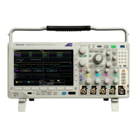
6. The TPA-N-VPI Adapter allows you to use TekVPI probes in the RF input. For more information on the many probes available for use with MDO3000 series oscilloscopes, refer to www.tektronix.com. A Tour of Your Instrument Front-Panel Menus, Controls, and Connectors Overview The front panel has buttons and controls for the functions that you use most often. -
Page 29: Rear-Panel Connectors
A Tour of Your Instrument 8. Dedicated RF input with N-connector 9. Analog channel (1, 2, (3, 4)) inputs with TekVPI versatile probe interface 10. Digital channel input 11. Display: shows frequency or time domain 12. Arbitrary waveform generator (AFG) enable button Rear-Panel Connectors 1. -
Page 30: Power-On And Power-Off Procedure
Power-On and Power-Off Procedure 6. USB 2.0 Host port. Use the USB 2.0 High Speed Host port to connect a USB memory device or USB keyboard. 7. Power input. Attach to an AC power line with integral safety ground. 8. Lock. Use to secure the oscilloscope. Power-On and Power-Off Procedure This instrument operates from a single-phase power source with the neutral conductor at or near earth ground. -
Page 31: Functional Check
Power-On and Power-Off Procedure Functional Check Perform this quick functional check to verify that your oscilloscope is operating correctly. 1. Connect the oscilloscope power cable as described in Powering On the Oscilloscope. (See page 22, Power-On and Power-Off Procedure.) 2. Power on the oscilloscope. 3. -
Page 32: Compensating A Tpp0250, Tpp0500B Or Tpp1000 Passive Voltage Probe
Power-On and Power-Off Procedure 4. Push Default Setup. 5. Push Autoset. The screen should now display a square wave, approximately 5 V at 1 kHz. If the signal appears but is misshapen, perform the procedures for compensating the probe. (See page 24.) If no signal appears, rerun the procedure. - Page 33 Power-On and Power-Off Procedure 1. Connect the oscilloscope power cable. 2. Power on the oscilloscope. 3. Connect the probe connector to the oscilloscope channel, and the probe tip and reference lead to the PROBE COMP terminals on the oscilloscope front panel. NOTE.
-
Page 34: Application Module Free Trial
Power-On and Power-Off Procedure When compensating TPP0250, TPP0500B, and TPP1000 probes on the MDO3000 Series oscilloscopes: Each channel can store compensation values for 10 individual probes. If you try to compensate an 11th probe on a channel, the oscilloscope will delete the values for the least recently used probe and add the values for the new probe. -
Page 35: Upgrading Firmware
Upgrading Firmware To upgrade the firmware of the oscilloscope: 1. Open a Web browser and go to www.tektronix.com/software. Proceed to the software finder. Download the latest firmware for your oscilloscope to your Unzip the files and copy the firmware.img file into the root folder of a USB flash drive. -
Page 36: Connecting Your Oscilloscope To A Computer
Web-enabled tools, and a socket server. Use VISA to communicate with your oscilloscope from your computer through a software application, such as Tektronix OpenChoice Desktop®. Use e*Scope to communicate with your oscilloscope through a Web browser, such as Google Chrome or Microsoft Internet Explorer. - Page 37 Power-On and Power-Off Procedure Setting up the oscilloscope 1. Connect the oscilloscope to your computer with the appropriate USB or Ethernet cable. for connectivity To communicate between the oscilloscope and a GPIB system, connect the oscilloscope to the TEK-USB-488 GPIB-to-USB Adapter with a USB cable. Then connect the adapter to your GPIB system with a GPIB cable.
- Page 38 These include toolbars that speed connectivity with Microsoft Excel and Word. There is also a standalone acquisition program called Tektronix OpenChoice Desktop. The rear-panel USB 2.0 device port is the correct USB port for computer connectivity. Use the rear and front panel USB 2.0 host ports to connect your oscilloscope to USB flash drives.
-
Page 39: Getting Acquainted With The Oscilloscope
Getting Acquainted with the Oscilloscope Getting Acquainted with the Oscilloscope The front panel has buttons and controls for the functions that you use most often. Use the menu buttons to access more specialized functions. Using the Menu System To use the menu system: 1. - Page 40 Getting Acquainted with the Oscilloscope 2. Push a lower button to select a menu item. If a pop-out menu appears, turn multipurpose knob a to select the desired choice. If a pop-up menu appears, push the button again to select the desired choice. 3.
-
Page 41: Using The Menu Buttons
Getting Acquainted with the Oscilloscope Using the Menu Buttons Use the menu buttons to perform many functions in the oscilloscope. 1. Measure. Push to perform automated measurements on waveforms. 2. Search. Push to search through an acquisition for user-defined events/criteria. 3. -
Page 42: Using Spectral Analysis Controls
Getting Acquainted with the Oscilloscope 11. Vertical Position. Turn to adjust the vertical position of the corresponding waveform. Push to center the waveform baseline indicator. 12. Channel 1, 2, 3, or 4 Menu. Push to set vertical parameters for input waveforms and to display or remove the corresponding waveform from the display. -
Page 43: Using Other Controls
Getting Acquainted with the Oscilloscope Using Other Controls These buttons and knobs control waveforms, cursors, and other data input. 1. Cursors. Push once to activate the two vertical cursors. Push again to turn off all cursors. Push and hold to bring up the cursor menu. Use the menu to select the cursor features, such as type, source, orientation, linked status, and units. - Page 44 Getting Acquainted with the Oscilloscope 7. Zoom button. Push to activate zoom mode. 8. Pan (outer knob). Turn to scroll the zoom window through the acquired waveform. 9. Zoom-scale (inner knob). Turn to control the zoom factor. Turning it clockwise zooms in further. Turning it counterclockwise zooms out. 10.
- Page 45 Getting Acquainted with the Oscilloscope 16. Autoset. Push to automatically set the vertical, horizontal, and trigger controls for a usable, stable display. 17. Single. Push to make a single sequence acquisition. 18. Run/Stop. Push to start or stop acquisitions. 19. Trigger Level. Turn to adjust the trigger level. Push Level to Set 50%.
-
Page 46: Identifying Items In The Time Domain Display
Getting Acquainted with the Oscilloscope 22. Power switch. Push to power on or off the oscilloscope. 23. USB 2.0 Host port. Insert a USB peripheral to the oscilloscope, such as a keyboard or a flash drive. 24. Save. Push to perform an immediate save operation. The save operation uses the current save parameters, as defined in the Save / Recall menu. - Page 47 Getting Acquainted with the Oscilloscope 3. The expansion point icon (an orange triangle) shows the point that the horizontal scale expands and compresses around. To make the expansion point the same as the trigger point, push Acquire and set the lower menu Delay item to Off.
- Page 48 Getting Acquainted with the Oscilloscope 9. The trigger readout shows the trigger source, slope, and level. The trigger readouts for other trigger types show other parameters. 10. The top line of the record length/sampling rate readout shows the sampling rate. You can adjust it with the Horizontal Scale knob. The bottom line shows the record length.
- Page 49 Getting Acquainted with the Oscilloscope the expected numerical measurement if a vertical clipping condition exists. Part of the waveform is above or below the display. To obtain a proper numerical measurement, turn the vertical scale and position knobs to make all of the waveform appear in the display.
-
Page 50: Identifying Items In The Frequency Domain Display
Getting Acquainted with the Oscilloscope Identifying Items in the Frequency Domain Display Activate the frequency domain display by pressing the front panel RF button. 1. Vertical graticule labels 2. Start frequency 3. Reference level 4. Vertical scale 5. Center frequency 6. -
Page 51: Identifying Items In The Arbitrary Function Generator Display
Getting Acquainted with the Oscilloscope Identifying Items in the Arbitrary Function Generator Display 1. If visible, the output is on 2. AFG label 3. Waveform type, e.g. “Sine” 4. Additive Noise icon 5. Frequency 6. Amplitude MDO3000 Installation and Safety Instructions... -
Page 52: Identifying Items In The Digital Voltmeter Display
Getting Acquainted with the Oscilloscope Identifying Items in the Digital Voltmeter Display 1. Measurement type 2. Value of current measurement 3. Graphic (min, max, value, five-second rolling range) 4. Min 5. Max 6. Average 7. Frequency MDO3000 Installation and Safety Instructions... -
Page 53: まえがき
まえがき まえがき このマニュアルでは、次のオシロスコープの設置方法と操作方法について説 明します。 MDO3104 MDO3054 MDO3034 MDO3024 MDO3014 MDO3102 MDO3052 MDO3032 MDO3022 MDO3012 人体への損傷を避け、本製品や本製品に接続されている製品への損傷を 防止するための、安全性に関する要注意事項 本製品が適合している EMC 基準、安全基準、および環境基準 本製品を使用するための電圧、電力、および環境要件 設置手順 電源投入、電源切断の手順 前面パネルと後部パネルのコントロールおよびコネクタ 時間、周波数、任意波形ファンクション・ゼネレータ、デジタル電圧計の各 ディスプレイ 保証期間 保証期間 保証期間 説明 MDO3000 オシロスコープ:3 年間保証 詳細については、『electronic (PDF) user manual (エレクトロニック (PDF) ユーザー・ P6316、TPP0250、TPP0500B、TPP1000 マニュアル)』の冒頭にある「warranties... - Page 54 FlexRay シリアル・トリガおよび解析 MDO3USB USB トリガおよび解析 (LS、FS、HS)。 高速はデコード専用で、1 GHz モデルでのみ使用可能。 MDO3LMT Limit/Mask テスト MDO3PWR 電力測定解析 MDO3000 シリーズのオシロスコープと連携し Tektronix Web サイト (www.tektronix.com/probes) の Oscilloscope て機能する TekVPI プローブ Probe and Accessory Selector Tool を参照 TPA-BNC TekVPI-TekProbe II BNC アダプタ。 オプショナル機器のアップグレード 当社部品番号 説明 MDO3AFG 任意波形ファンクション・ゼネレータ...
-
Page 55: マニュアル
まえがき マニュアル 本製品のマニュアルと参照先を、以下の表に示します。マニュアルのメディア には、冊子、CD-ROM、Tektronix Web サイト(www.tektronix.com)の 3 種類が あります。 表 5: 製品マニュアル 項目 内容 参照先 設置と安全性に関する手順書(本マ 印 刷 マ ニ ュア ル 。 PDF 版 は 安全性とコンプライアンスに関する情 ニュアル) 報、ハードウェアの設置手順および www.tektronix.com/manuals で入手 禁止事項(警告)について説明しま できます。 す。英語版、日本語版、簡体字中国 語版の 3 種類があります。 ユーザ・マニュアル 操作方法および用途について説明し 製品マニュアル CD。PDF 版は... -
Page 56: 安全性に関する重要な情報
安全性に関する重要な情報 安全性に関する重要な情報 このマニュアルには、操作を行うユーザの安全を確保し、製品を安全な状態に 保つために順守しなければならない情報および警告が記載されています。 このセクションの最後には、製品を安全に保守するために必要な追加情報が 記載されています。(51 ページ 「安全に保守点検していただくために」 参照)。 安全にご使用いただくために 製品は指定された方法でのみご使用ください。人体への損傷を避け、本製品 や本製品に接続されている製品の破損を防止するために、安全性に関する次 の注意事項をよくお読みください。すべての指示事項を注意深くお読みくださ い。必要なときに参照できるように、説明書を安全な場所に保管しておいてく ださい。 該当する地域および国の安全基準に従ってご使用ください。 本製品を正しく安全にご使用になるには、このマニュアルに記載された注意 事項に従うだけでなく、一般に認められている安全対策を徹底しておく必要が あります。 本製品は訓練を受けた専門知識のあるユーザによる使用を想定しています。 製品のカバーを取り外して修理や保守、または調整を実施できるのは、あらゆ る危険性を認識した専門的知識のある適格者のみに限定する必要があります。 使用前に、既知の情報源と十分に照らし合わせて、製品が正しく動作している ことを常にチェックしてください。 本製品は危険電圧の検出用にはご利用になれません。 危険な通電導体が露出している部分では、感電やアーク・フラッシュによって けがをするおそれがありますので、保護具を使用してください。 本製品をご使用の際に、より大きな他のシステムにアクセスしなければならない 場合があります。他のシステムの操作に関する警告や注意事項については、 その製品コンポーネントのマニュアルにある安全に関するセクションをお読み ください。 本機器をシステムの一部としてご使用になる場合には、そのシステムの構築者 が安全性に関する責任を果たさなければなりません。 火災や人体への損傷を 適切な電源コードを使用してください: 本製品用に指定され、使用される国で 認定された電源コードのみを使用してください。 避けるには 他の製品の電源コードは使用しないでください。 本製品を接地してください: 本製品は、電源コードのグランド線を使用して接 地します。感電を避けるため、グランド線をアースに接続する必要があります。... - Page 57 安全性に関する重要な情報 本製品の入出力端子に接続する前に、本製品が正しく接地されていることを 確認してください。 電源コードのグランド接続を無効にしないでください。 電源の切断: 電源コードの取り外しによって主電源が遮断されます。スイッチ の位置については、使用説明書を参照してください。電源コードの取り扱いが 困難な場所には設置しないでください。必要に応じてすぐに電源を遮断できる ように、ユーザが常にアクセスできる状態にしておく必要があります。 着脱は正しく行ってください: プローブとテスト・リードが電圧源に接続されて いる間は、それらを取り付けたり取り外したりしないでください。 電圧プローブ、テスト・リード、およびアダプタは、製品に付属した絶縁された ものか、当社が製品に使用できると明示したもののみを使用してください。 すべての端子の定格に従ってください: 火災や感電の危険を避けるために、 本製品のすべての定格とマーキングに従ってください。本製品に電源を接続 する前に、定格の詳細について、製品マニュアルを参照してください。測定カ テゴリ(CAT)の定格および電圧と電流の定格については、製品、プローブ、ま たはアクセサリのうちで最も低い定格を超えないように使用してください。1:1 の テスト・リードを使用するときは、プローブ・チップの電圧が直接製品に伝送さ れるため注意が必要です。 コモン端子を含むいかなる端子にも、その端子の最大定格を超える電圧をか けないでください。 コモン端子の定格電圧を超えてコモン端子をフローティングさせないでくださ い。 カバーを外した状態で動作させないでください: カバーやパネルを外した状 態やケースを開いたまま動作させないでください。危険性の高い電圧に接触 してしまう可能性があります。 露出した回路への接触は避けてください: 電源が投入されているときに、露出 した接続部分やコンポーネントに触れないでください。 故障の疑いがあるときは使用しないでください: 本製品に故障の疑いがある 場合には、資格のあるサービス担当者に検査を依頼してください。 製品が故障している場合には、使用を停止してください。製品が故障してい る場合や正常に動作していない場合には、製品を使用しないでください。安 全上の問題が疑われる場合には、電源を切って電源コードを取り外してくださ い。誤って使用されることがないように、問題のある製品を区別できるようにし...
- Page 58 安全性に関する重要な情報 使用する前に、製品の外観に変化がないかよく注意してください。ひび割れや 欠落した部品がないことを確認してください。 指定された交換部品のみを使用するようにしてください。 適切なヒューズを使用してください: 本製品用に指定されたヒューズ・タイプお よび定格のみを使用してください。 湿気の多いところでは動作させないでください: 機器を寒い場所から暖かい 場所に移動する際には、結露にご注意ください。 爆発性のガスがある場所では使用しないでください: 製品の表面を清潔で乾燥した状態に保ってください: 製品の清掃を開始する 前に、入力信号を取り外してください。 適切に通気してください: 適切な通気が得られるように製品を設置できるよう に、マニュアルの設置手順を参照してください。 製品には通気用のスロットや開口部があります。その部分を覆ったり、通気が 妨げられたりすることがないようにしてください。開口部には異物を入れないで ください。 安全な作業環境を確保してください: 製品は常にディスプレイやインジケータ がよく見える場所に設置してください。 キーボードやポインタ、ボタン・パッドは正しく使用し、長時間の連続使用は避 けてください。キーボードやポインタの使用方法を誤ると、身体に深刻な影響 が及ぶ可能性があります。 作業場が該当する人間工学規格を満たしていることを確認してください。ストレ スに由来するけががないように、人間工学の専門家に助言を求めてください。 本製品には指定された当社のラック取り付け金具のみを使用してください。 プローブやテスト・リードを接続する前に、電源コードを使用して本機を適切に プ ロ ー ブ お よ び テ ス ト ・ 接地された...
-
Page 59: 安全に保守点検していただくために
安全性に関する重要な情報 上記の 2 つの電圧定格はプローブと用途によって異なります。詳細について は、プローブのマニュアルの仕様関連セクションを参照してください。 警告: 感電を防止するために、オシロスコープの入力 BNC コネクタ、プロー ブ・チップ、またはプローブ基準リードの最大測定電圧や最大フローティング 電圧を超えないように注意してください。 着脱は正しく行ってください: プローブ出力を測定器に接続してから、プロー ブを被測定回路に接続してください。被測定回路にプローブの基準リードを 接続してから、プローブ入力を接続してください。プローブ入力とプローブの 基準リードを被測定回路から切断した後で、プローブを測定器から切断してく ださい。 着脱は正しく行ってください: 電流プローブの接続や切断は、被測定回路か ら電力が失われた後に行ってください。 プローブの基準リードは、グランドにのみ接続してください。 電流プローブを、その定格電圧を超える電圧の電線に接続しないでください。 プローブとアクセサリを検査してください: 使用前には必ずプローブとアクセ サリに損傷がないことを確認してください(プローブ本体、アクセサリ、ケーブル 被覆などの断線、裂け目、欠陥)。損傷がある場合には使用しないでください。 グランド基準のオシロスコープの使用: グランド基準のオシロスコープで使用 する場合、プローブの基準リードはフローティングさせないでください。基準リー ドは接地電位(0 V)に接続しなければなりません。 安全に保守点検していただくために 「安全に保守点検していただくために」のセクションには、製品の保守点検を 安全に行うために必要な詳細な情報が記載されています。資格のあるサービ ス担当者以外は、保守点検手順を実行しないでください。保守点検を行う前 には、この「安全に保守点検していただくために」と「安全にご使用いただくた めに」を読んでください。 感電を避けてください: 露出した接続部には触れないでください。 保守点検は単独で行わないでください: 応急処置と救急蘇生ができる人がい ないかぎり、本製品の内部点検や調整を行わないでください。... -
Page 60: 本マニュアル内の用語
安全性に関する重要な情報 け、コンポーネントの交換をする前に、電源の切断、バッテリの取り外し(可能 な場合)、テスト・リードの切断を行ってください。 修理後の安全確認: 修理を行った後には、常にグランド導通と電源の絶縁耐 力を再チェックしてください。 本マニュアル内の用語 このマニュアルでは次の用語を使用します。 警告: 人体や生命に危害をおよぼすおそれのある状態や行為を示します。 注意: 本機やその他の接続機器に損害を与えるおそれのある状態や行為を 示します。 本製品に使用される記号と用語 本製品では、次の用語を使用します。 危険: ただちに人体や生命に危険をおよぼす可能性があることを示しま す。 警告: 人体や生命に危険をおよぼす可能性があることを示します。 注意: 本製品を含む周辺機器に損傷を与える可能性があることを示しま す。 製品にこの記号が表記されているときは、マニュアルを参照して、想定 される危険性とそれらを回避するために必要な行動について確認し てください。(マニュアルでは、この記号はユーザに定格を示すため に使用される場合があります)。 本製品では、次の記号を使用します。 MDO3000 Installation and Safety Instructions... -
Page 61: 適合性に関する情報
IEC 61000-4-2:2001:静電気放電イミュニティ IEC 61000-4-3:2002:RF 電磁界イミュニティ IEC 61000-4-4:2004:電気的ファースト・トランジット/バースト・イミュニティ IEC 61000-4-5:2001:電力線サージ・イミュニティ IEC 61000-4-6:2003:伝導 RF イミュニティ IEC 61000-4-11:2004:電圧低下と停電イミュニティ EN 61000-3-2:2006: AC 電源高調波エミッション EN 61000-3-3:1995: 電圧の変化、変動、およびフリッカ 欧州域内連絡先: Tektronix UK, Ltd. Western Peninsula Western Road Bracknell, RG12 1RF United Kingdom 本製品は住居区域以外での使用を目的としたものです。住居区域で使用すると、電磁干 渉の原因となることがあります。 本製品をテスト対象に接続した状態では、この規格が要求するレベルを超えるエミッショ ンが発生する可能性があります。 ここに挙げた各種 EMC 規格に確実に準拠するには、高品質なシールドを持つインタフェー... -
Page 62: 安全性
適合性に関する情報 70%/25 サイクルの電圧低下および 0%/250 サイクル瞬断の各テスト・レベルにおいて、性 能基準 C を適用します(IEC 61000-4-11)。 オーストラリア/ニュー ACMA に従い、次の規格に準拠することで Radiocommunications Act の EMC 条項に適合しています。 ジ ー ラ ン ド 適 合 宣 言 - CISPR 11:2003 : グ ル ー プ 1 、 ク ラ ス A 、 放 射 お よ び 伝 導 エ ミ ッ シ ョ ン (EN61326-1:2006 および... - Page 63 適合性に関する情報 その他の適合性 IEC 61010-1:測定、制御、および実験用途の電子装置に対する安全基準 – 第 1 部:一般要件。 IEC 61010-2-030:測定、制御、および研究用途の電子装置に対する安全 基準、第 2-030 部:試験および測定回路に固有の必要条件。 機器の種類 テスト機器および計測機器。 感電保護クラス クラス 1 - アース付き製品。 汚染度について 製品内部およびその周辺で発生する可能性がある汚染度の尺度です。通常、 製品の内部環境は外部環境と同じとみなされます。製品は、その製品に指定 されている環境でのみ使用してください。 汚染度 1:汚染なし、または乾燥した非導電性の汚染のみが発生します。 このカテゴリの製品は、通常、被包性、密封性のあるものか、クリーン・ルー ムでの使用を想定したものです。 汚染度 2:通常、乾燥した非導電性の汚染のみが発生します。ただし、結 露によって一時的な導電性が発生することもまれにあります。これは、標準 的なオフィスや家庭内の環境に相当します。一時的な結露は製品非動作 時のみ発生します。 汚染度 3:伝導性のある汚染、または通常は乾燥して導電性を持たないが 結露時に導電性を帯びる汚染。これらは、温度、湿度のいずれも管理され ていない屋内環境に相当します。日光や雨、風に対する直接の曝露から は保護されている領域です。 汚染度 4:導電性のある塵、雨、または雪により持続的に導電性が生じて いる汚染。これは一般的な屋外環境に相当します。...
- Page 64 適合性に関する情報 測定および過電圧カテゴ 本製品の測定端子は、測定する電源電圧について次の 1 つまたは複数のカ テゴリに評価されます。 リについて カテゴリ II:固定設備の屋内配線に直接接続される回路(壁コンセントお よび類似する設備)。 カテゴリ III:屋内配線および配電系統。 カテゴリ IV:建物に電気を供給する起点部分。 注: 過電圧カテゴリ定格に該当するのは主電源回路のみです。測定カテゴリ 定格に該当するのは測定回路のみです。製品内部のその他の回路にはいず れの定格も該当しません。 過電圧カテゴリ II(IEC 61010-1 の定義による)。 主電源過電圧カテゴリ定 格 MDO3000 Installation and Safety Instructions...
-
Page 65: 環境条件について
リに関する指令 2002/96/EC および 2006/66/EC に基づき、EU の 諸要件に準拠していることを示しています。リサイクル方法について は、当社の Web サイト(www.tektronix.com)のサービス・セクションを 参照してください。 過 塩 素 酸 塩 の 取 り 扱 い : 本 製 品 に は CR リ チ ウ ム 電 池 が 搭 載 さ れ て... -
Page 66: 動作の要件
動作の要件 動作の要件 このセクションでは、製品を安全かつ正しく使用するために把握しておくべき 仕様について説明します。詳細については、『MDO3000 Technical Reference (MDO3000 テクニカル・リファレンス)』の製品仕様を参照してください。 MDO3000 オシロスコープは、従来のアナログ信号の測定と分析を行うための ものです。また、組込みの任意波形ファンクション・ゼネレータ、(デジタルとア ナログの) 混合信号、スペクトラム・アナライザの各機能を使用する必要がある 問題を解決するためのものでもあります。 電源入力周波数: MDO3000 シリーズ・オシ 100 V ~ 240 V、50/60 Hz ロスコープ 115 V、400 Hz (±10%) 電源入力電圧範囲:100 V ~ 240 V 最大電力入力 (ワースト・ケース):最大 120 ワット 最大測定入力電圧: アナログ入力:1 MΩ 最大入力電圧:前面パネル・コネクタでは 300 V 、イン... - Page 67 動作の要件 図 2: MDO3000 シリーズ TPP0250 、 TPP0500B 、 最大入力電圧:300 V CAT II 安全基準 TPP1000 受動プローブ 温度: 動作時:–15 ℃ ~ +65 ℃ 非動作時:–62 ℃ ~ +85 ℃ 湿度:相対湿度 5 ~ 95% 動作時:相対湿度 5% ~ 95% (+30 ℃ 以下)、相対湿度 5% ~ 75% (+30 ℃ 超、 +65 ℃...
-
Page 68: 電気定格
動作の要件 非動作時:-20 ℃~ +60 ℃ 高度: 動作時:最高 3,000 m 非動作時:最高 12,000 m 汚染度:2、ただし、屋内使用のみ 湿度: 40 ℃以下で相対湿度 5% ~ 90% 中心周波数範囲: スペクトラム・アナライザ 9k Hz から 3.0 GHz (MDO3SA をインストールした場合) 9k Hz から 1.0 GHz (MDO310X、標準) 9k Hz から 500 MHz (MDO305X、標準) 9k Hz から... -
Page 69: 入力定格
動作の要件 本製品の電源要件は次のとおりです。 片方の通電導体が接地またはその近傍の電位の(中性線)単相電源。 注: 両方の通電導体が接地に対して電位を持つ方式(多相方式における相 間など)は、電源として推奨されません。 電源周波数および電圧の仕様については、「動作の要件」を参照してくだ さい。 . (58 ページ参照)。 ライン側にのみ、過電流保護のためにヒューズが付けられています。この内蔵 ヒューズ ヒューズはユーザによる交換を想定したものではありません。ヒューズの交換 はしないでください。ヒューズが飛んでいると思われる場合は、認定サービス・ センターに機器を返送して修理を受けてください。 バッテリ 本機器には、ユーザが交換可能なバッテリは含まれていません。 入力定格 表 6: 最大入力電圧 入力 定格 前面パネル BNC コネクタ、 1 300 V 、インストール・カテゴリ II。4.5MHz から 45MHz までは 20 dB/decade、 45Mhz から 450MHz までの範囲では 14db の低下。450Mhz を超える場合、5VRMS。 MΩ... -
Page 70: 物理仕様
動作の要件 表 7: 環境仕様, (続き) 特性 説明 湿度 動作時 +40 ℃以下で 5% ~ 90% の相対湿度(RH) +40 ℃ 超、+55 ℃ 以下で 5% ~ 60% の相対湿度(RH)、結露なし。 非動作時 +40 ℃ 以下で 5% ~ 90% の相対湿度(RH) +40 ℃ 超、+55 ℃ 以下で 5% ~ 60% の相対湿度(RH) +55 ℃... -
Page 71: 設置手順
設置手順 設置手順 オシロスコープとプローブは次の方法で接続できます。 プローブの接続 1. Tektronix 汎用プローブ・インタフェース(TekVPI) これらのプローブは、画面上のメニューおよびリモート設定可能な機能を 通して、オシロスコープとの双方向通信をサポートしています。リモート・コ ントロールは、システムがプローブのパラメータをプリセットする ATE のよう なアプリケーションで役に立ちます。 2. 受動プローブ用 Tektronix 汎用プローブ・インタフェース(TekVPI) これらのプローブは TekVPI インタフェースの機能に基づいています。各プ ローブをオシロスコープの対応するチャンネルとマッチさせ、オシロスコー プの入力パスを最適化します。 これにより、全周波数帯域に AC 補正が 適用されます。 3. TPA-BNC 型アダプタ TPA-BNC アダプタにより、プローブに電源を供給したりスケーリング情報 や単位情報をオシロスコープに送るような、TEKPROBE II プローブの機能 が使用可能になります。 4. BNC インタフェース MDO3000 Installation and Safety Instructions... -
Page 72: ご使用機器のツアー
ご使用機器のツアー これらのインタフェースの中には TEKPROBE 機能を使用して波形信号と スケーリング情報をオシロスコープに送るものもありますが、波形信号のみ を送るものもあります。 5. ロジック・プローブ・インタフェース P6316 型プローブは、16 チャンネルのデジタル(オン/オフ状態)情報を 提供します。 6. TPA-N-VPI アダプタを使用すると、RF 入力で TekVPI プローブを使用で きます。 MDO3000 シリーズ・オシロスコープで使用可能な各種プローブの詳細につい ては、www.tektronix.com を参照してください。 ご使用機器のツアー 前面パネルのメニュー、コントロール、コネクタ 概要 前面パネルには、頻繁に使用する機能に対するボタンとコントロールが備えら れています。メニュー・ボタンを使用すると、さらに高度な機能にアクセスできま す。 1. 従来のオシロスコープ前面パネル・コントロール 2. 10 個の数字で構成されたキーパッド 3. アプリケーション・モジュール・スロット 4. グランド・ストラップ・コネクタ 5. グランド... -
Page 73: 後部パネル・コネクタ
ご使用機器のツアー 6. PROBE COMP(プローブ補正) 7. スペクトラム解析専用コントロール 8. RF 専用入力 (N コネクタ) 9. アナログ・チャネル (1、2、(3、4)) (TekVPI 汎用プローブ・インタフェース) 10. デジタル・チャンネル入力 11. ディスプレイ:周波数領域または時間領域を表示します。 12. 任意波形ゼネレータ (AFG) を有効にするボタン 後部パネル・コネクタ 1. AFG OUT (AFG 出力)。AFG OUT ポートは、任意波形ファンクション・ゼ ネレータからの信号を送信する場合に使用します。 2. AUX OUT (AUX 出力) 3. LAN。LAN(イーサネット)ポート(RJ-45 コネクタ)を使用して、10/100 Base-T ローカル・エリア・ネットワークにオシロスコープを接続します。... -
Page 74: 電源投入、電源切断の手順
電源投入、電源切断の手順 5. USB 2.0 Device port (USB 2.0 デバイス・ポート)。USB 2.0 高速デバイス・ ポートに PictBridge 対応プリンタを接続します。また、USBTMC プロトコル を使用して、PC からオシロスコープを直接制御することもできます。 注: USB 2.0 デバイス・ポートとホスト・コンピュータを接続するケーブルは、高 速ホスト・コントローラに接続する場合の高速動作に関する USB2.0 仕様に準 拠していなければなりません。 6. USB 2.0 ホスト・ポート。USB メモリ・デバイスまたは USB キーボードに接続 する場合、USB 2.0 高速ホスト・ポートを使用します。 7. Power input (電源入力)。アース付きの AC 電源ケーブルを接続します。 8. -
Page 75: 機能チェック
電源投入、電源切断の手順 電源の遮断 1. 前面パネルの電源ボタンを押して、本製品をオフにします。 2. 電源を完全に遮断するには、後部パネルから電源コードを引き抜きます。 機能チェック 以下の簡単な機能チェックを実行して、オシロスコープが正常に動作している か確認します。 1. 「オシロスコープの電源の投入」の説明に従って、オシロスコープの電源 ケーブルを接続します。 (66 ページ 「電源投入、電源切断の手順」 参照)。 2. オシロスコープの電源をオンにします。 3. 適切な TPP0250、TPP0500B、TPP1000 型プローブ・チップと基準リードを、 オシロスコープの PROBE COMP コネクタに接続します。 MDO3000 Installation and Safety Instructions... -
Page 76: Tpp0250 型、Tpp0500B 型、Tpp1000 型受動電圧プローブの補正
電源投入、電源切断の手順 4. Default Setup(工場出荷時設定)を押します。 5. オートセットを押します。振幅約 5 V、周波数 1 kHz の方形波が画面に表 示されます。 信号は表示されているのに形状がゆがんでいる場合は、プローブの補正 手順を実行します。 (68 ページ参照)。 信号が表示されない場合は、同じ手順を再度実行します。それでも問題 が解消されない場合は、資格のあるサービス担当者にオシロスコープの修 理を依頼してください。 TPP0250 型、TPP0500B 型、TPP1000 型受動電圧プローブの補正 MDO3000 シリーズ・オシロスコープは、TPP0250 型、TPP0500B 型、TPP1000 型プローブを自動的に補正することができます。これにより、他のプローブで は必要な手動によるプローブの補正作業が不要となります。 補正では、特定のプローブとチャンネルの組み合わせに応じて、複数の値が 生成されます。そのプローブを他のチャンネルで使用するために、プローブと チャンネルの新たな組み合わせで補正する場合は、その組み合わせについて 一連の新規補正ステップを実行しなければなりません。 MDO3000 Installation and Safety Instructions... - Page 77 電源投入、電源切断の手順 1. オシロスコープの電源コードを接続します。 2. オシロスコープの電源をオンにします。 3. プローブ・コネクタをオシロスコープのチャンネルに接続し、プローブのチッ プと基準リードをオシロスコープの前面パネルにある PROBE COMP 端子 に接続します。 注: 同時に複数のプローブをプローブの補正端子に接続することはできませ ん。 4. 補正するプローブに接続している入力チャンネルの前面パネル・ボタンを 押します (1、2、3、4 のいずれか)。 5. 下のメニューに、プローブの終端値が自動的に設定されていることに注意 してください。 6. More(次へ)を繰り返し押して、表示されるポップアップ・メニューからProbe Setup(プローブ設定)を選択します。 7. 補正ステータスは、Default(デフォルト)から始まることに注意してください。 8. Compensate probe(プローブの補正)を押して、画面に表示される指示に 従います。 MDO3000 Installation and Safety Instructions...
-
Page 78: アプリケーション・モジュールの無料トライアル
電源投入、電源切断の手順 MDO3000 シリーズ・オシロスコープで TPP0250 型、TPP0500B 型、TPP1000 型プローブの補正を行う場合は次のことに注意してください。 各チャンネルには、プローブ 10 本分の補正値が保存されます。特定の チャンネルで 11 本目のプローブの補正を行うと、使用された最も古いプ ローブの値が削除され、新しいプローブの値が追加されます。 Aux In (Aux 入力) チャンネルに接続された TPP0250 型、TPP0500B 型、 TPP1000 型プローブには、デフォルトの補正値が割り当てられます。 注: 工場での校正を行うと格納された補正値はすべて消去されます。 注: プローブの補正が失敗した場合、その原因の多くは、プローブ・チップま たはグランド接続の補正中の断続的な接続不良です。補正に失敗した場合、 プローブ補正の失敗前に補正値が存在すれば、その補正値が引き続き使用 されます。 アプリケーション・モジュールの無料トライアル オシロスコープにインストールされていないアプリケーション・モジュールは、ど れも 30 日間無料で試用できます。トライアル期間は、初めてオシロスコープの 電源をオンにした時点から起算されます。 30 日経過後も継続使用するには、モジュールをご購入いただく必要がありま す。トライアル期間の終了日を確認するには、次のようにします。 前面パネルの... -
Page 79: ファームウェアのアップグレード
電源投入、電源切断の手順 ファームウェアのアップグレード: オシロスコープのファームウェアをアップグレードするには、次の手順を実行 します。 1. Web ブラウザを開いて、www.tektronix.com/software にアクセスし、ソフト ウェア・ファインダを実行します。ご使用のオシロスコープ用の最新ファー ムウェアを PC にダウンロードします。 ダウンロードしたファイルを解凍し、firmware.img ファイルを USB フラッシュ・ ドライブのルート・フォルダにコピーします。 2. オシロスコープの電源を切ります。 3. USB フラッシュ・ドライブをオシロスコープの前面パネルにある USB ポート に挿入します。 4. オシロスコープの電源をオンにします。アップグレード用ファームウェアが 自動的に認識され、インストールされます。 ファームウェアのインストールが開始されない場合は、同じ手順を再度実 行します。手順を繰り返してもインストールできない場合は、別の USB フ ラッシュ・ドライブを試してください。それでも問題が解決しない場合は、当 社営業所にご連絡ください。 注: ファームウェアのインストールが完了するまで、オシロスコープの電源を 切ったり、USB フラッシュ・ドライブを取り外したりしないでください。 5. オシロスコープの電源を切って、USB フラッシュ・ドライブを取り外します。... -
Page 80: オシロスコープとコンピュータの接続
のブラウザを使用してください。 注: スクリーン・イメージや波形データを保存する方法を含め、オシロスコープ をコンピュータに接続する方法について詳しくは、『electronic (PDF) MDO3000 User Manual (エレクトロニック (PDF) MDO3000 ユーザ・マニュアル)』を参照し てください。 VISA の使用 VISA を使用すると、オシロスコープから Windows コンピュータへデータを取り込 み、そのデータを Microsoft Excel、National Instruments LabVIEW、Tektronix OpenChoice デスクトップ・ソフトウェア、その他の解析パッケージ(独自開発プ ログラムを含む)で使用することができます。USB、イーサネット、GPIB などの 一般的な通信接続を使用して、コンピュータをオシロスコープに接続すること もできます。 VISA 用に、VISA ドライバをコンピュータに読み込みます。また、OpenChoice デ スクトップなどのアプリケーションを読み込みます。VISA ドライバと OpenChoice デスクトップ・ソフトウェアは、オシロスコープに付属の CD に収録されています。... - Page 81 電源投入、電源切断の手順 LAN ポートを使用して、オシロスコープをご使用のネットワークに接続します。 組込み LXI Web インタフェース (Core 2011 バージョン 1.4) には、編集およ びカスタマイズ可能なネットワーク構成情報が備わっています。また、e*Scope ユーザ・インタフェースを使用してリモート機器制御を行うこともできます。ここ では、機器設定の制御、スクリーン・イメージの保存、機器データまたはセット アップの保存などを行うことが可能です。これらの操作すべては、パスワードで 保護可能な Web インタフェースを使用して行います。 接 続 の た め の オ シ ロ ス 1. 適切な USB ケーブルまたはイーサネット・ケーブルを使用して、オシロス コープをコンピュータに接続します。 コープの設定 オシロスコープと GPIB システム間で通信を行うには、USB ケーブルを使用 してオシロスコープを TEK-USB-488 GPIB-USB アダプタに接続します。次 に、GPIB ケーブルを使用して、アダプタを...
- Page 82 5. 必要に応じて、メニュー項目を選択します。詳細については、『MDO3000 User Manual (MDO3000 ユーザ・マニュアル』を参照してください。 ヒント オシロスコープに付属している CD には、オシロスコープとコンピュータ間 を効率的に接続するためのさまざまな Windows 用ソフトウェア・ツールが収 録されています。Microsoft Excel および Word との接続を迅速化するツー ルバーが用意されています。Tektronix OpenChoice デスクトップというスタ ンドアローンのアクイジション・プログラムも備わっています。 後部パネルの USB 2.0 デバイス・ポートは、コンピュータとの接続に使用 します。後部パネルおよび前面パネルの USB 2.0 ホスト・ポートを使用し て、オシロスコープと USB フラッシュ・ドライブを接続します。USB デバイ ス・ポートを使用して、PC または PictBridge 対応プリンタに接続します。 USB ホスト・ポート...
-
Page 83: オシロスコープの概要
オシロスコープの概要 オシロスコープの概要 前面パネルには、頻繁に使用する機能に対するボタンとコントロールが備えら れています。メニュー・ボタンを使用すると、さらに高度な機能にアクセスできま す。 メニュー・システムの使用 メニュー・システムを使用するには、次の手順を実行します。 1. 前面パネルのメニュー・ボタンを押して、使用するメニューを表示します。 MDO3000 Installation and Safety Instructions... - Page 84 オシロスコープの概要 2. 下部のボタンを押して、メニュー項目を選択します。ポップアウト・メニュー が表示された場合は、汎用ノブ a を回して目的の項目を選択します。さら にポップアップ・メニューが表示された場合は、ボタンを再度押して、目的 の項目を選択します。 3. 側面ボタンを押して、サイド・メニュー項目を選択します。 メニュー項目が複数の選択肢を含む場合は、側面ボタンを繰り返し押し て、選択肢を繰り返し表示させます。 ポップアウト・メニューが表示された場合は、汎用ノブ a を回して目的の項 目を選択します。 MDO3000 Installation and Safety Instructions...
-
Page 85: メニュー・ボタンの使用
オシロスコープの概要 メニュー・ボタンの使用 メニュー・ボタンを使用すると、オシロスコープのさまざまな機能が実行できま す。 1. 波形測定。このボタンを押すと、波形の自動測定を実行します。 2. 検索。このボタンを押すと、取り込んだ波形を調べてユーザ定義のイベン ト/基準の状況を確認することができます。 3. オートセット。このボタンを押すと、オシロスコープの設定を自動的にセッ トアップできます。 4. テスト。このボタンを押すと、高度なあるいはアプリケーション固有のテスト 機能が起動します。 5. 波形取込。このボタンを押すと、アクイジション・モードを設定してレコード 長を調節することができます。 6. 「トリガ」の「メニュー」。このボタンを押すと、トリガ設定が指定できます。 7. M。このボタンを押すと、演算波形の管理(表示/非表示の切り替えなど) ができます。 8. R。このボタンを押すと、リファレンス波形の管理(表示/非表示の切り替え など)ができます。 9. B1 または B2。適切なアプリケーション・モジュールがある場合は、これらの ボタンを押すことで、シリアル・バスを定義または表示することができます。 MDO3000 製品ではパラレル・バスも使用できます。 MDO3000 Installation and Safety Instructions... -
Page 86: スペクトラム解析コントロールの使用
オシロスコープの概要 さらに、B1 または B2 ボタンを押すと、対応するバスを表示したり、削除し たりもできます。 10. AFG。押すと、任意波形ファンクション・ゼネレータが有効になります。 11. 「垂直軸」の「位置」。このボタンを回すと、対応する波形の垂直軸位置が調 整できます。押すと、波形ベースライン・インジケータが中心位置に来ます。 12. チャンネル 1、2、3、4 の「メニュー」。これらのボタンを押すと、入力波形 の垂直軸パラメータを設定したり、対応する波形をディスプレイに表示した り、ディスプレイから消去したりできます。 13. 「垂直軸」の「スケール」。このボタンを回すと、対応する波形の垂直軸ス ケール・ファクタ(V/div)を調整できます。微調整を押すと、より微細な調整 が行えます。 スペクトラム解析コントロールの使用 以下のボタンを使用して、RF 入力のアクイジションおよびディスプレイを構成 します。 1. RF。周波数領域のディスプレイとメニューを表示する場合に押します。 2. 周波数/スパン。どの部分のスペクトラムをディスプレイに表示するかを指 定する場合に押します。周波数またはスパンの中心を設定するか、開始周 波数および停止周波数を設定します。 3. 振幅。基準レベルを設定する場合に押します。 4. 帯域幅。分解能帯域幅を定義する場合に押します。 5. マーカ。自動マーカまたは手動マーカを設定するときに押します。 MDO3000 Installation and Safety Instructions... -
Page 87: 他のコントロールの使用
オシロスコープの概要 他のコントロールの使用 これらのボタンとノブを使用すると、波形、カーソル、および他のデータ入力を 制御できます。 1. カーソル。このボタンを一度押すと、2 つの垂直カーソルがオンになります。 再度押すと、カーソルはすべてオフになります。押したままにすると、カー ソル・メニューが表示されます。このメニューを使用して、タイプ、ソース、向 き、リンク・ステータス、単位などのカーソル機能を選択します。 カーソルがオンの場合は、汎用ノブを回してその位置を調節できます。 2. 上側の汎用ノブ a(アクティブ時)。カーソル移動、メニュー項目のパラメー タ数値の設定、または、ポップアウト・リストの項目選択に使用します。微調 整ボタンを押すと、粗調整と微調整を切り替えできます。 a あるいは b がアクティブな場合は、画面のアイコンにより示されます。 3. 選択。このボタンを押すと、その時々の状況に応じた機能がオンになりま す。 例えば、2 つの垂直カーソルを使用している場合(水平カーソルはオフ)、 このボタンを押すとカーソルをリンクさせたり、リンクを解除したりできます。 2 つの垂直カーソルと 2 つの水平カーソルが両方ともオンの場合は、この ボタンを押して垂直カーソルまたは水平カーソルのいずれかをアクティブ にできます。 4. 微調整。汎用ノブ a と b のさまざまな操作を使用するときに、粗調整と微 調整を切り替える場合に押します。 5. 下側の汎用ノブ b(アクティブ時)。カーソル移動、またはメニュー項目の パラメータ数値の設定に使用します。微調整を押すと、さらにゆっくりと調... - Page 88 オシロスコープの概要 7. ズーム ボタン。このボタンを押すと、ズーム・モードがオンになります。 8. パン(外側ノブ)。このノブを回すと、取り込んだ波形内でズーム・ウィンド ウをスクロールできます。 9. ズーム (内側ノブ)。このノブを回すと、ズーム・ファクタを制御できます。時 計回りに回すと、さらにズーム・インします。反時計回りに回すと、ズーム・ アウトします。 10. 実行/停止ボタン。このボタンを押すと、波形の自動パンを開始または停 止できます。速度および方向を制御するには、パン・ノブを使用します。 11. ← (前)。このボタンを押すと、前の波形マークに移動します。 12. 「マーク」の「設定/クリア」。このボタンを押すと、波形マークを設定または 削除できます。 13. → (次)。このボタンを押すと、次の波形マークに移動します。 14. 「水平軸」の「位置」。このボタンを回すと、取込んだ波形に対するトリガ・ポ イントの相対位置を調整できます。ディスプレイがオンの場合に押すと、中 心に位置するようになります。ディスプレイがオフの場合に押すと、10% に 設定されます。 15. 「水平軸」の「スケール」。このボタンを回すと、水平軸スケール(時間 /div) を調整できます。 MDO3000 Installation and Safety Instructions...
- Page 89 オシロスコープの概要 16. オートセット。このボタンを押すと、適切な安定した表示のための垂直、水 平、およびトリガ・コントロールを自動で設定できます。 17. シングル。このボタンを押すと、シングル・シーケンス・アクイジションを実 行します。 18. 実行/停止。このボタンを押すと、アクイジションを開始または停止できま す。 19. 「トリガ」の「レベル」。このボタンを回すと、トリガ・レベルを調整できます。 50% 振幅。トリガのレベル・ノブを押すと、トリガ・レベルが波形の中間点に 設定されます。 20. 強制トリガ。このボタンを押すと、イベントをただちに強制的にトリガします。 MDO3000 Installation and Safety Instructions...
- Page 90 オシロスコープの概要 21. 印刷。このボタンを押して、選択したプリンタに印刷します。 22. 電源スイッチ。オシロスコープの電源をオンまたはオフにします。 23. USB 2.0 ホスト・ポート。キーボードやフラッシュ・ドライブなどの USB 周辺 機器をオシロスコープに接続します。 24. Save (保存)。このボタンを押すと、ただちに保存操作が実行されます。保 存操作では、Save / Recall (保存/復元)メニューで定義された現在の保 存パラメータが使用されます。 25. Save / Recall (保存/復元) メニュー。このボタンを押すと、設定、波形、ス クリーン・イメージを内部メモリまたは USB フラッシュ・ドライブに保存するこ とや、これらのデータを呼び出すことができます。 26. Default Setup (工場出荷時設定)。このボタンを押すと、オシロスコープが ただちにデフォルト設定に戻ります。 27. Utility (ユーティリティ)。このボタンを押すと、言語の選択または日時の設 定などのシステム・ユーティリティ機能が起動します。 28. D15 - D0。このボタンを押すと、ディスプレイでデジタル・チャンネルの表 示/非表示を切り替えたり、デジタル・チャンネルのセットアップ・メニュー...
-
Page 91: 時間領域表示の項目
オシロスコープの概要 時間領域表示の項目 次の図に示されている項目が、画面に表示されます。ある時点において、これ らの項目がすべて表示されているわけではありません。リードアウトの中には、 メニューがオフになると目盛領域の外側に移動するものもあります。 1. アクイジション・リードアウトは、アクイジションが実行中である、停止してい る、あるいはアクイジション・プレビューが有効であることを示します。 2. トリガ位置アイコンは、アクイジション内でのトリガの位置を示します。 3. 拡大中心ポイント・アイコン(オレンジ色の三角形)は、水平スケールを拡 大および縮小する中心のポイントを示します。拡大中心ポイントをトリガ・ポ イントと一致させるには、波形取込を押して、下のメニューの Delay(遅延) 項目を Off(オフ)に設定します。 MDO3000 Installation and Safety Instructions... - Page 92 オシロスコープの概要 4. 波形レコード・ビューは、波形レコードに対するトリガの位置を示します。ラ インの色は、選択した波形の色に対応しています。角カッコは、画面に現 在表示されているレコードの部分を表します。 5. トリガ・ステータス・リードアウトは、トリガのステータスを示します。 6. 入力ポートが無効になると、セキュリティ・アイコンにそのことが示されます。 7. カーソル・リードアウトは、それぞれのカーソルに対して時間、振幅、および 差(Δ)を示します。FFT 測定の場合は、周波数および振幅を示します。 シリアル・バスおよびパラレル・バスの場合、リードアウトにはデコードされ た値が表示されます。 8. トリガ・レベル・アイコンは、波形上でのトリガ・レベルを示します。アイコン の色は、トリガ・ソースの色に対応しています。 9. トリガ・リードアウトには、トリガのソース、スロープ、およびレベルが表示さ れます。リードアウトに表示されるパラメータは、トリガの種類によって異な ります。 10. レコード長/サンプリング・レートのリードアウトの上段にはサンプリング・ レートが表示されます。「水平軸」の「スケール」ノブを使用して調整すること MDO3000 Installation and Safety Instructions...
- Page 93 オシロスコープの概要 ができます。下段にはレコード長が表示されます。下のメニューのAcquire (波形取込) および Record Length (レコード長) を押して調整できます。 11. 水平位置/スケール・リードアウトは、上部のラインで水平スケールを示し ます(「水平軸」の「スケール」ノブを使用して調整)。Delay Mode(遅延モー ド)がオンの場合、下部のラインで T シンボルから拡張ポイント・アイコンま での時間を示します(「水平軸」の「位置」ノブを使用して調整)。水平位置 を使用して、トリガが発生した時間と実際にデータを取込んだ時間との間 の追加された遅延を挿入します。負の時間を挿入すると、さらにプリトリガ 情報を取込みます。Delay Mode(遅延モード)がオフの場合、下部のライン でアクイジション内でのトリガの時間位置を比率で示します。 12. タイミング分解能のリードアウトには、デジタル・チャンネルのタイミング分解 能が表示されます。タイミング分解能とは、サンプル間の時間のことです。 これは、デジタル・サンプル・レートの逆数です。MagniVu コントロールがオ ンの場合、リードアウトには "MagniVu" と表示されます。 13. 測定リードアウトには、選択した測定が表示されます。一度に最大 8 つの 測定を選択して、表示できます。この 記号が、垂直方向にクリッピング 状態が存在する場合に、得られる測定値の代わりに表示されます。波形の 残りの部分は、表示の上または下にあります。適切な測定値を得るには、 垂直スケールと位置のノブを回して、画面内に波形をすべて表示します。 14. 補助波形リードアウトは、演算およびリファレンス波形の垂直軸および水平 軸のスケール・ファクタを示します。...
- Page 94 オシロスコープの概要 16. デジタル・チャンネルの場合、ベースライン・インジケータはハイ・レベル とロー・レベルを示します。インジケータの色は、レジスタで使用されるカ ラー・コードに従っています。例えば、D0 インジケータは黒、D1 インジケー タは茶、D2 インジケータは赤で表示されます。 17. グループ・アイコンは、デジタル・チャンネルがグループ化されている場合 に表示されます。 18. バス・ディスプレイには、シリアル・バスまたはパラレル・バスのデコードされ たパケット・レベル情報が表示されます。バス・インジケータには、バス番号 とバスの種類が示されます。 19. アナログ・チャンネルの場合、波形ベースライン・インジケータは、波形の 0 V レベルを示します(オフセットは使用していない場合)。アイコンの色は、 波形の色に対応しています。 MDO3000 Installation and Safety Instructions...
-
Page 95: 周波数領域表示の項目
オシロスコープの概要 周波数領域表示の項目 周波数領域表示を有効にするには、前面パネルの RF ボタンを押します。 1. 垂直目盛りラベル 2. 開始周波数 3. 基準レベル 4. 垂直軸スケール 5. 中心周波数 6. スパンおよび分解能帯域幅 7. 停止周波数 8. 基準マーカ MDO3000 Installation and Safety Instructions... -
Page 96: 任意波形ファンクション・ゼネレータ表示の項目
オシロスコープの概要 任意波形ファンクション・ゼネレータ表示の項目 1. 表示される場合、出力がオン 2. AFG ラベル 3. 波形タイプ (正弦波など) 4. ノイズ追加アイコン 5. 周波数 6. 振幅 MDO3000 Installation and Safety Instructions... -
Page 97: デジタル電圧計表示の項目
オシロスコープの概要 デジタル電圧計表示の項目 1. 測定の種類 2. 現在の測定値 3. グラフィック (最小値、最大値、値、5 秒のロール範囲) 4. 最小 5. 最大 6. 平均 7. 周波数 MDO3000 Installation and Safety Instructions... - Page 98 オシロスコープの概要 MDO3000 Installation and Safety Instructions...
-
Page 99: 附件和可更换部件
前言 前言 本手册介绍下列示波器的安装和操作: MDO3104 MDO3054 MDO3034 MDO3024 MDO3014 MDO3102 MDO3052 MDO3032 MDO3022 MDO3012 有关避免人身伤害,并防止损坏本产品或与本产品连接的任何产品的 安全性预防措施 仪器遵循的 EMC(电磁兼容性)、安全和环境标准 使用本产品的电压、功率和环境要求 安装步骤 开机和关机步骤 前面板和后面板控件和连接器 时间、频率、任意波形函数发生器和数字电压表显示器 保修 保修 保修 说明 MDO3000 示波器:三年保修 有关详情,请参阅电子版 (PDF) 用户 手册前面的保修部分 P6316、TPP0250、TPP0500B 和 TPP1000 探头:一年保修 附件和可更换部件 可选附件 Tektronix 部件号... - Page 100 购买 MDO3000 系 列 产 品 后 升级 模 拟 带 宽 。 访 问 www.tektronix.com,了解有关可用升级产品的信息。 文档 下表列出了为本产品提供的文档,并且显示了可从何处获取这些文档: 以 印 刷 手 册 形 式 提 供 , 也 可 从 产 品 文 档 CD-ROM 或 Tektronix 网 站 www.tektronix.com 上获取。 表 9: 产品文档 项目...
- Page 101 前言 表 9: 产品文档, (续) 项目 用途 位置 技术规格和性能验证技术参考 技术规格和仪器性能检查步骤。 可 从 产 品 文 档 CD 中 以 及 www.tektronix.com/manuals 上获 取 程序员手册 用于远程控制仪器的命令参考。 可 从 产 品 文 档 CD 中 以 及 www.tektronix.com/manuals 上获 取 维修手册 提供有关调整、维修和可更换部件...
-
Page 102: 重要安全信息
重要安全信息 重要安全信息 本手册包含用户必须遵守的信息和警告,以确保安全操作并保持产品的安 全状态。 为保证安全地对本产品进行维修,本部分结尾还提供其他信息。( 见第97 维修安全概要 页, 常规安全概要 请务必按照规定使用产品。详细阅读下列安全性预防措施,以避免人身伤 害,并防止损坏本产品或与本产品连接的任何产品。认真阅读所有说明。 保留这些说明以备将来参考。 遵守当地和国家安全法令。 为了保证正确安全地操作产品,除本手册规定的安全性预防措施外,您还 必须遵守普遍公认的安全规程。 产品仅限经过培训的人员使用。 只有了解相关危险的合格人员才能进行开盖维修、保养或调整。 使用前,请务必检查产品是否来自已知来源,以确保正确操作。 本产品不适用于检测危险电压。 如果有危险的带电导体暴露,请使用个人保护装备以防电击和强电弧伤 害。 使用此产品时,可能需要接触到更大系统的其他部分。有关操作此系统的 警告和注意事项,请阅读其他组件手册的安全性部分。 将本设备集成到某系统时,该系统的安全性由系统的组装者负责。 避免火灾或人身伤害 使用合适的电源线: 只使用本产品专用并经所在国家/地区认证的电源线。 不要使用为其他产品提供的电源线。 将产品接地: 本产品通过电源线的接地导线接地。为避免电击,必须将接 地导线与大地相连。在对本产品的输入端或输出端进行连接之前,请务必 将本产品正确接地。 不要切断电源线的接地连接。 断开电源: 电源线可以使产品断开电源。请参阅有关位置的说明。请勿将 设备放在难以操作电源线的位置;必须保证用户可以随时操作电源线,以 在需要时快速断开连接。 正确连接和断开: 探头或测试导线连接到电压源时请勿插拔。 MDO3000 Installation and Safety Instructions... - Page 103 重要安全信息 仅使用产品附带的或 Tektronix 指明适合产品使用的绝缘电压探头、测 试导线和适配器。 遵循所有终端的额定值: 为避免火灾或电击危险,请遵循产品上所有的额 定值和标记说明。在连接产品之前,请先查看产品手册,了解额定值的详 细信息。不要超过本产品、探头或附件中各组件的额定值最低的测量类别 (CAT) 额定值和电压或电流额定值。在使用 1:1 测试导线时要小心,因为 探头端部电压会直接传输到产品上。 对任何终端(包括公共终端)施加的电压不要超过该终端的最大额定值。 请勿将公共终端浮动到该终端的额定电压以上。 切勿开盖操作: 请勿在外盖或面板拆除或机壳打开的状态下操作本产品。 可能有危险电压暴露。 远离裸露电路: 电源接通后请勿接触外露的接头和元件。 在怀疑存在故障时请勿进行操作: 如果怀疑本产品已损坏,请让合格的维 修人员进行检查。 产品损坏时请勿使用。本产品损坏或运行错误时请勿使用。如果怀疑产 品存在安全问题,请关闭产品并断开电源线。并做清晰标记以防其再被使 用。 在使用之前,请检查电压探头、测试导线和附件是否有机械损坏,如损坏 则予以更换。如果探头或测试导线损坏、金属外露或出现磨损迹象,请勿 使用。 在使用之前请先检查产品外表面。查看是否有裂纹或缺失部件。 仅使用规定的替换部件。 使用合适的保险丝: 只能使用为本产品指定的保险丝类型和额定值。 请勿在潮湿环境下操作: 请注意,如果某个单元从冷处移到暖处,则可能 发生凝结情况。 请勿在易燃易爆的环境下操作: 保持产品表面清洁干燥: 在清洁本产品时,请先拔掉输入信号。...
- Page 104 重要安全信息 请确保工作区符合适用的人体工程学标准。请咨询人体工程学专家,以避 免应激损伤。 仅限使用为本产品指定的 Tektronix 机架安装硬件。 探头和测试导线 连接探头或测试导线之前,请将电源线从电源连接器连接到正确接地的电 源插座。 请将手指放在探头上手指防护装置的后面。 拔掉所有不用的探头、测试导线和附件。 仅使用正确的测量类别 (CAT)、电压、温度、海拔高度和电流额定的探 头、导线和适配器进行测量。 小心高电压: 了解您正在使用的探头的额定电压,请不要超出这些额定 值。重要的是知道并理解两个额定值: 探头端部到探头参考导线的最大测量电压。 探头参考导线到大地的最大浮动电压 这两个额定电压取决于探头和您的应用。请参阅手册的“技术规格”部分 了解更多详情。 警告: 为防止电击,请不要超出示波器输入 BNC 连接器、探头端部或探 头参考导线的最大测量电压或最大浮动电压。 正确连接和断开: 将探头连接到被测电路之前,先将探头输出端连接到测 量产品。在连接探头输入端之前,请先将探头参考导线与被测电路连接。 将探头与测量产品断开之前,请先将探头输入端及探头参考导线与被测电 路断开。 正确连接和断开: 连接电流探头或断开电流探头的连接之前请将被测电路 断电。 只能将探头参考导线连接到大地。 不要将电流探头连接到电压超过电流探头的电压额定值的任何导线。 检查探头和附件: 在每次使用之前,请检查探头和附件是否损坏(探头本 体、附件、电缆外壳等的割裂、破损、缺陷)。如果损坏,请勿使用。 以地参考的示波器使用: 在使用以地参考的示波器时,不要将此探头的参...
-
Page 105: 维修安全概要
重要安全信息 维修安全概要 “维修安全概要”部分包含安全执行维修所需的其他信息。只有合格人员 才能执行维修程序。在执行任何维修程序之前,请阅读此“维修安全概 要”和“常规安全概要”。 避免电击: 接通电源时,请勿触摸外露的连接。 请勿单独进行维修: 除非现场有他人可以提供急救和复苏措施,否则请勿 对本产品进行内部维修或调整。 断开电源: 为避免电击,请先关闭仪器电源并断开与市电电源的电源线, 然后再拆下外盖或面板,或者打开机壳以进行维修。 带电维修时要小心操作: 本产品中可能存在危险电压或电流。在卸下保护 面板,进行焊接或更换元件之前,请先断开电源,卸下电池(如适用)并 断开测试导线。 维修后验证安全性: 请务必在维修后重新检查接地连续性和市电介电强 度。 本手册中的术语 本手册中可能使用以下术语: 警告: “警告”声明指出可能会造成人身伤害或危及生命安全的情况或 操作。 注意: “注意”声明指出可能对本产品或其他财产造成损坏的情况或操 作。 产品上的符号和术语 产品上可能出现以下术语: DANGER(危险)表示您看到该标记时可直接导致人身伤害的危险。 WARNING(警告)表示您看到该标记时不会直接导致人身伤害的危险。 CAUTION(注意)表示可能会对本产品或其他财产带来的危险。 产品上标示此符号时,请确保查阅手册,以了解潜在危险的类别 以及避免这些危险需采取的措施。(此符号还可能用于指引用户 参阅手册中的额定值信息。) MDO3000 Installation and Safety Instructions... -
Page 106: 符合性信息
CISPR 11:2003。放射和传导发射量,组 1,A 类 IEC 61000-4-2:2001。静电放电抗扰性 IEC 61000-4-3:2002。射频电磁场抗扰性 IEC 61000-4-4:2004。电气快速瞬变/突发抗扰性 IEC 61000-4-5:2001。电源线路浪涌抗扰性 IEC 61000-4-6:2003。 传导射频抗扰性 IEC 61000-4-11:2004。电压跌落和中断抗扰性 EN 61000-3-2:2006: 交流电源线谐波辐射 EN 61000-3-3:1995: 电压变化、波动和闪烁 欧洲联系方式: Tektronix UK, Ltd. Western Peninsula Western Road Bracknell, RG12 1RF United Kingdom(英国) 本产品仅在非居民区内使用。在居民区内使用可能造成电磁干扰。 MDO3000 Installation and Safety Instructions... -
Page 107: 安全符合性
符合性信息 当该设备与测试对象连接时,可能产生超过此标准要求的辐射级别。 为确保符合上面列出的 EMC 标准,应使用高质量的屏蔽接口电缆。 示波器:≤3.0 分度波形位移,峰-峰值噪声增加 ≤6.0 分度。RF:仪器处于 IEC 61000-4-3 测试中频率低于 1 GHz 的电磁干扰之下时,射频部分残余杂散信号通常上升至 -50 dBm, 频率高于 1 GHz 时上升至 -35 dBm。 示波器:≤1.0 分度波形位移,峰-峰值噪声增加 ≤2.0 分度。RF:仪器处于 IEC 61000-4-6 测试中的电磁干扰之下时,射频部分残余杂散信号通常上升至 –85 dBm。 性能标准 C 应用于 70%/25 周期电压跌落以及 0%/250 周期电压中断测试水平 (IEC 61000-4-11)。 澳大利亚/新西兰一致性... - Page 108 符合性信息 加拿大认证 CAN/CSA-C22.2 No. 61010-1。对用于测量、控制和实验室的电气设备 的安全性要求 - 第 1 部分:总体要求。 CAN/CSA-C22.2 No. 61010-2-030。对用于测量、控制和实验室的电气 设备的安全性要求 - 第 2-030 部分:对测试和测量电路的特殊要求。 其他符合性 IEC 61010-1。对用于测量、控制和实验室的电气设备的安全性要求 - 第 1 部分:总体要求。 IEC 61010-2-030。对用于测量、控制和实验室的电气设备的安全性要 求 - 第 2-030 部分:对测试和测量电路的特殊要求。 设备类型 测试和测量设备。 安全级别 1 级 - 接地产品。 污染度说明 对产品周围和产品内部环境中可能出现的污染的一种量度。通常认为产品...
- Page 109 符合性信息 测量和过压类别说明 本产品上的测量端子可能适合测量以下一种或多种类别的市电电压(请参 阅产品和手册中标示的具体额定值)。 类别 II。电路使用点(插座和类似点处)直接连接到建筑物布线。 类别 III。在建筑物布线和配电系统中。 类别 IV。在建筑物电源处。 说明: 仅市电电源电路具有过压类别额定值。仅测量电路具有测量类别 额定值。产品中的其他电路不具有其中任何一种额定值。 市电过压类别额定值 过压类别 II(如 IEC 61010-1 中的定义)。 MDO3000 Installation and Safety Instructions...
-
Page 110: 环境注意事项
此符号表示该产品符合欧盟有关废旧电子和电气设备 (WEEE) 以及 电池的 2002/96/EC 和 2006/66/EC 号指令所规定的相关要求。有 关回收方式的信息,请查看 Tektronix 网站 (www.tektronix.com) 上的 Support/Service(支持/服务)部分。 高 氯 酸 盐 材 料 : 此 产 品 包 含 一 个 或 多 个 CR 型 锂 电 池 。 按 照 加 州 规... -
Page 111: 操作要求
操作要求 操作要求 本部分提供为安全正确地操作产品而需要了解的技术规格。有关更多信 息,请参阅 MDO3000 技术参考中完整的产品技术说明书。 MDO3000 示波器是专为传统的模拟信号测量和分析而设计的,可用于解决 需要使用其内置任意波形函数发生器、混合信号(数字和模拟)以及频谱 分析仪功能的问题。 MDO3000 系列示波器 主输入频率: 100 V 到 240 V、50/60 Hz。 115 V,400 Hz,±10% 主输入电压范围:100 V 至 240 V 最大功率输入(最坏情况):最大 120 瓦特 最大测量输入电压: 模拟输入:1 MΩ 最大输入电压:在前面板连接器处,300 V ,安装类 别 II” 模拟输入:50 Ω 和 75 Ω。最大输入电压:5 V ,在... - Page 112 操作要求 图 3: MDO3000 系列 TPP0250 、 TPP0500B 最大输入电压:300 V CAT II 安全要求 或 TPP1000 无源探头 温度: 工作温度:–15 ℃ 至 +65 ℃ 非工作温度:–62 ℃ 至 +85 ℃ 湿度:5% 到 95% RH 工作湿度:温度不高于 +30 ℃ 时,相对湿度 (%RH) 5% 到 95%;温度在 +30 C 至 +65 ℃ 时,5% 到 75% RH,无凝结 非工作湿度:温度在...
-
Page 113: 电源额定值
操作要求 非工作温度:-20 ℃ 至 +60 ℃ 海拔高度: 工作状态:最高 3000 米 非工作状态:最高 12000 米 污染度:2 级,仅室内使用 湿度: 在不高于 40 ℃ 时,相对湿度为 5% 到 90% 频谱分析仪 中心频率范围: 9k Hz 至 3.0 GHz(已安装 MDO3SA) 9k Hz 至 1.0 GHz(MDO310X,标配) 9k Hz 至 500 MHz(MDO305X,标配) 9k Hz 至... -
Page 114: 输入额定值
操作要求 仪器具有下列电源要求: 单相电源,其中有一根载流导线接地或近地(中性导线)。 说明: 两条载流导线的接地均带电(例如多相位系统中的相间电压)的 系统不建议用作电源。 有关主电源频率和电压指标的信息,请参阅操作要求。 . ( 见第103 页) 保险丝 只有线路导线装有保险丝以提供过流保护。保险丝为内置,不可由用户更 换。请勿尝试更换保险丝。如果您怀疑保险丝熔断了,请将该仪器送回授 权维修中心进行维修。 电池 仪器并不含有任何可由用户更换的电池。 输入额定值 表 10: 最大输入电压 输入 额定值 在前面板 BNC 连接器处。1 300 V ,安装类别 II;在 4.5MHz 和 45MHz 之间额定值以 20 dB/倍频程下 MΩ 降;在 45Mhz 和 450MHz 之间额定值按 14db 下降。高于 450Mhz,5VRMS。 最大输入电压,50 Ω... -
Page 115: 物理技术规格
操作要求 表 11: 环境规格, (续) 特性 说明 3,000 m 海拔高度 工作状态 12,000 m 非工作状态 物理技术规格 表 12: 物理技术规格 特性 说明 尺寸 高度 手柄以下 203.2 毫米,手柄以上 254 毫米 宽度 最宽 416.6 毫米 厚度 最厚 147.4 毫米 重量 净重 4.2 kg,独立仪器。 6.8 kg,带附件和携带箱。 发货... -
Page 116: 安装步骤
安装步骤 安装步骤 连接探头 示波器支持带以下部件的探头: 1. Tektronix 通用型探头接口 (TekVPI) 这些探头通过屏幕菜单和通过可编程支持的远程方式与示波器进行双 向通信。在希望系统预置探头参数的应用(如 ATE)中,远程控制十 分有用。 2. Tektronix 无源探头通用型探头接口 (TekVPI) 这些探头建立在 TekVPI 接口功能的基础之上。每个探头均配有其相 应的示波器通道,从而可让示波器优化其信号输入路径。这为频带提 供 AC 补偿。 3. TPA-BNC 适配器 TPA-BNC 适配器允许使用 TekProbe II 探头功能,例如提供探头电源、 将标度信息和单位传送到示波器。 4. BNC 接口 有些使用 TEKPROBE 功能将波形信号和标度传递到示波器。有些仅传 递信号,并无其他通信。 5. 逻辑探头接口... -
Page 117: 仪器概览
P6316 探头提供 16 条通道的数字(开关状态)信息。 6. TPA-N-VPI 适配器可让您在 RF 输入中使用 TekVPI 探头。 有 关 适 用 于 MDO3000 系 列 示 波 器 的 诸 多 探 头 的 详 细 信 息 , 请 参 阅 www.tektronix.com。 仪器概览 前面板菜单、控件和连接器 概述... -
Page 118: 后面板连接器
仪器概览 11. 显示器:显示频域或时域 12. 任意波形发生器 (AFG) 启用按钮 后面板连接器 1. AFG OUT(任意波形发生器输出)。使用 AFG OUT(任意波形发生器输 出)端口传输来自任意波形函数发生器的信号。 2. AUX OUT(辅助输出) 3. LAN(局域网)。使用 LAN(以太网)端口(RJ-45 连接器)将示波器 连接到 10/100 Base-T 局域网。 4. Video Out(视频输出)。使用 Video Out(视频输出)端口(DB-15 孔型连接器)在外部监视器或投影仪上显示示波器的显示器。 5. USB 2.0 Device port(USB 2.0 设备端口)。使用 USB 2.0 高速设备 端口连接... -
Page 119: 开机和关机步骤
开机和关机步骤 开机和关机步骤 本仪器使用带接地或近地中性导线的单相电源。线路导线上装有保险丝进 行过流保护。通过电源线中的接地导线提供保护性接地对于安全操作十分 重要。 开机 1. 将附带的电源线接到后面板上的电源连接器上。 2. 按仪器前面板上的电源按钮,仪器将会打开。 说明: 前面板上的待机按钮不会断开市电电源。仅产品后面的电源线可 以断开市电电源。 关机 1. 按仪器前面板上的电源按钮关闭仪器。 2. 如果要完全切断电源,请从仪器后面板断开电源线。 MDO3000 Installation and Safety Instructions... -
Page 120: 功能检查
开机和关机步骤 功能检查 执行此快速功能检查以验证示波器是否正常工作。 1. 按照“打开示波器电源”中的叙述连接示波器的电源线。 ( 见第111 开机和关机步骤 页, 2. 打开示波器电源。 3. 将探头 TPP0250、TPP0500B 或 TPP1000 端部和参考导线连接到示波器 的 PROBE COMP(探头补偿)连接器上。 4. 按“Default Setup(默认设置)”。 MDO3000 Installation and Safety Instructions... -
Page 121: 补偿 Tpp0250、Tpp0500B 或 Tpp1000 无源电压探头
开机和关机步骤 5. 按“Autoset(自动设置)”。屏幕上应出现一条大约 5 V,1 kHz 的 方波。 如果该信号出现,但已变形,请执行探头补偿过程。 ( 见第113页) 如果未出现信号,请重新运行该过程。如果仍未解决,请将示波器交 由合格的维修人员进行维修。 补偿 TPP0250、TPP0500B 或 TPP1000 无源电压探头 MDO3000 系列示波器可以自动补偿 TPP0250、TPP0500B 和 TPP1000 探头。 省去了其他探头通常所需的手动探头补偿。 每次补偿均为特定探头和通道组合生成对应的值。如果您想在其他通道上 使用探头并补偿新的探头-通道组合,则必须执行一组适用于新组合的补 偿步骤。 1. 连接示波器电源线。 2. 打开示波器电源。 3. 将探头连接器连接到示波器通道,将探头端部和参考导线连接到示波 器前面板上的 PROBE COMP(探头补偿)端子上。 说明: 每次仅将一个探头连接到探头补偿端子上。 MDO3000 Installation and Safety Instructions... - Page 122 开机和关机步骤 4. 按下前面板按钮,将输入通道连接到您希望予以补偿的探头。(1、 2、3 或 4) 5. 观察下部菜单,表明示波器已自动设置探头端子值。 6. 重复按“More(更多)”,从产生的弹出菜单中选择“Probe Setup (探头设置)”。 7. 注意补偿状态开始为“Default(默认)”。 8. 按下“Compensate probe(补偿探头)”并遵照屏幕上的指示进行操 作。 在 MDO3000 系列示波器上补偿 TPP0250、TPP0500B 和 TPP1000 探头时: 每条通道能存储 10 个探头的补偿值。如果尝试在通道上补偿第 11 个 探头,示波器将删除最早使用过的探头的值,然后增加新探头的值。 示波器将向 Aux In(辅助输入)通道上所连接的 TPP0250、TPP0500B 或 TPP1000 探头分配默认的补偿值。 说明: 出厂校准将删除存储的所有补偿值 说明:...
-
Page 123: 应用模块免费试用
30 天以后如想继续使用该应用程序,您必须购买该模块。查看免费试用 期的到期日: 按下前面板“Utility(辅助功能)”按钮。 按下屏幕“Utility Page(辅助功能页面)”按钮。 使用通用旋钮“a”选择“Config(配置)”。 按下屏幕“About(关于)”按钮。 按“Application Modules(应用模块)”侧菜单。 升级固件 要升级示波器的固件,请执行以下操作: 1. 打开 Web 浏览器访问 www.tektronix.com/software。前进到软件查找 部分。将适用的示波器最新固件下载到 PC 上。 解压文件并将 firmware.img 文件复制到 U 盘的根文件夹内。 2. 关闭示波器的电源。 3. 将 U 盘插入示波器前面板的 USB 端口。 4. 打开示波器电源。示波器自动识别并安装更换固件。 如果示波器未安装固件,请重新运行该过程。如果问题仍然存在,请 尝试其他型号的 U 盘。最后如果需要,请联络合格的维修人员。 说明:... -
Page 124: 将示波器连接到计算机
有关升级固件的更多信息,请参阅电子版 (PDF) MDO3000 用户手 册。 将示波器连接到计算机 将示波器直接连接到计算机,可通过 PC 分析数据、收集屏幕图像或控制 示波器。 将示波器与计算机连接的方法有三种,即通过 VISA 驱动程序、e*Scope® Web 工具和套接字服务器。使用 VISA 通过软件应用程序(如 Tektronix OpenChoice Desktop®)使计算机与示波器进行通信。使用 e*Scope 通过 Web 浏览器(如 Google Chrome 或 Microsoft Internet Explorer)与示 波器进行通信。为获得最佳结果,请使用支持 html 5 的浏览器。 说明: 有关将示波器连接至计算机的更多信息(包括有关如何保存屏幕 图像和波形数据),请参阅电子版 (PDF) MDO3000 用户手册。... - Page 125 开机和关机步骤 设置示波器以便连接 1. 使用合适的 USB 或以太网电缆将示波器连接到计算机。 要在示波器和 GPIB 系统之间进行通信,请使用 USB 电缆将示波器连 接到 TEK-USB-488 GPIB-to-USB 适配器。然后使用 GPIB 电缆将该适 配器连接到 GPIB 系统。关闭后再打开示波器的电源。 2. 按“Utility(辅助功能)”。 3. 按“Utility Page(辅助功能页面)”。 4. 旋转通用旋钮“a”选择“I/O”。 5. 按要求执行菜单项。有关更多详细信息,请参阅 MDO3000 用户手册。 MDO3000 Installation and Safety Instructions...
- Page 126 开机和关机步骤 快速提示 示波器附带的 CD 含有各种基于 Windows 的软件工具,可用于有效 连接示波器与计算机。所含的工具栏可以加速与 Microsoft Excel 和 Word 的连接。还有一个称为 Tektronix OpenChoice Desktop 的独立 采集程序。 后面板 USB 2.0 设备端口是正确用于计算机连接的 USB 端口。使用前 后面板上的 USB 2.0 主机端口将示波器连接到 U 盘。使用 USB 设备 端口将示波器连接到 PC 或 PictBridge 打印机。 USB 主机端口 USB 设备端口...
-
Page 127: 熟悉示波器
熟悉示波器 熟悉示波器 前面板具有最常用功能的按钮和控件。使用菜单按钮可以访问特殊的功 能。 使用菜单系统 要使用菜单系统,请执行下列操作: 1. 按某个前面板菜单按钮以显示要使用的菜单。 MDO3000 Installation and Safety Instructions... - Page 128 熟悉示波器 2. 按下方按钮选择菜单项。如果出现弹出式菜单,旋转通用旋钮“a”选 择所需的选项。如果出现弹出式菜单,请再次按下按钮选择所需的选 项。 3. 按某个侧面按钮以选择侧菜单项。 如果菜单项包含多个选项,可重复按下侧按钮查看全部选项。 如果出现弹出式菜单,旋转通用旋钮“a”选择所需的选项。 MDO3000 Installation and Safety Instructions...
-
Page 129: 使用菜单按钮
熟悉示波器 使用菜单按钮 使用菜单按钮执行示波器中的许多功能。 1. Measure(测量)。按此按钮对波形执行自动测量。 2. Search(搜索)。按此按钮在捕获数据中搜索用户定义的事件/标准。 3. Autoset(自动设置)。按此按钮可以对示波器的设置执行自动设置。 4. Test(测试)。按此按钮可激活高级的或应用特定的测试功能。 5. Acquire(采集)。按此按钮可以设置采集模式和调整记录长度。 6. Trigger Menu(触发菜单)。按此按钮可以指定触发设置。 7. M。按此按钮可以管理数学运算波形,包括显示数学运算波形或删除所 显示的数学运算波形。 8. R。按此按钮可以管理参考波形,包括显示每个参考波形或删除所显示 的参考波形。 9. B1 或 B2。如果有对应的应用模块,则按下即可定义和显示串行总线。 在 MDO3000 产品上提供并行总线支持。 另外,按 B1 或 B2 按钮可显示总线或删除所显示的相应总线。 10. AFG。按此按钮即可启用任意波形函数发生器。 11. Vertical Position(垂直位置)。旋转这些旋钮可以调整相应波形的 垂直位置。按此按钮即可让波形基线指示器处于中间位置。 MDO3000 Installation and Safety Instructions... -
Page 130: 使用频谱分析控件
熟悉示波器 12. 通道 1、2、3 或 4 菜单。按下即可以设置输入波形的垂直参数,并 在显示器上显示或删除相应的波形。 13. Vertical Scale(垂直标度)。旋转此旋钮可以调整相应波形的垂直 标度系数(伏特/格)。按“Fine(精细)”可以进行更小调整。 使用频谱分析控件 这些按钮配置 RF 输入的采集和显示。 1. RF。按此按钮即可启动频域画面和菜单。 2. Freq/Span(频率/频宽)。按此按钮,即可指定在显示器上查看的频 谱部分。设置中心频率和频宽 — 或设置初始频率和终止频率。 3. Ampl。按此按钮即可设置参考电平。 4. BW(带宽)。按此按钮即可定义分辨率带宽。 5. Markers(标记)。按此按钮即可设置自动或手动标记。 MDO3000 Installation and Safety Instructions... -
Page 131: 使用其它控件
熟悉示波器 使用其它控件 这些按钮和旋钮控制波形、光标和其他数据输入。 1. Cursors(光标)。按一次可激活两个垂直光标。再按一次将关闭所有 光标。按住此按钮即可显示光标菜单。使用菜单选择光标功能,如类 型、来源、方向、链接状态和单位。 光标打开时,可以旋转通用旋钮以控制其位置。 2. 激活后,旋转上方的通用旋钮“a”可以移动光标、设置菜单项的数字 参数值或从选项的弹出列表中进行选择。按“Fine(精细)”按钮可 以在粗调和细调之间进行切换。 当“a”或“b”被激活时,屏幕图标会提示您。 3. Select(选择)。按此按钮可以激活特殊功能。 例如,当使用两个垂直光标(水平光标不可见)时,可以按此按钮链 接光标或取消光标之间的链接。当两个垂直光标和两个水平光标都可 见时,可以按此按钮激活垂直光标或水平光标。 4. Fine(精细)。按此按钮,即可充分利用通用旋钮“a”和“b”在粗 调和细调之间进行切换。 5. 激活时,旋转下方通用旋钮“b”,可以移动光标或设置菜单项的数字 参数值。按“Fine(精细)”可更缓慢地进行调整。 6. Intensity(亮度)。按下可用通用旋钮“a”控制波形的显示亮度, 用旋钮“b”控制刻度亮度。 MDO3000 Installation and Safety Instructions... - Page 132 熟悉示波器 7. Zoom(缩放)按钮。按此按钮可激活缩放模式。 8. Pan(平移)(外环旋钮)。旋转该环可以在采集的波形上滚动缩放窗 口。 9. Zoom-scale(缩放比例)(内环旋钮)。旋转该旋钮可以控制缩放系 数。顺时针旋转可以放大。逆时针旋转可以缩小。 10. Play-pause(播放/暂停)按钮。按此按钮可以开始或停止波形的自动 平移。使用平移旋钮控制速度和方向。 11. ← Prev(← 上一个)。按此按钮可以跳到上一波形标记。 12. Set/Clear Mark(设置/清除标记)。按此按钮可以建立或删除波形标 记。 13. → Next(→下一个)。按此按钮可以跳到下一波形标记。 14. Horizontal Position(水平位置)。旋转此旋钮可以调整触发点相对 于采集的波形的位置。延迟开启时,按此按钮即可对准中心位置。延 迟关闭时,按此按钮即可设置为 10%。 15. Horizontal Scale(水平标度)。旋转此旋钮可以调整水平标度(时 间/格)。 MDO3000 Installation and Safety Instructions...
- Page 133 熟悉示波器 16. Autoset(自动设置)。按此按钮可以自动设置垂直、水平和触发控制 以进行有用、稳定的显示。 17. Single(单次)。按此按钮进行单一序列采集。 18. Run/Stop(运行/停止)。按此按钮可以开始或停止采集。 19. Trigger Level(触发电平)。旋转此旋钮可以调整触发电平。 Push Level to Set 50%(按下设为 50%)。按“触发电平”旋钮可将 触发位置设为波形的中点。 20. Force Trig(强制触发)。按此按钮可以强制执行立即触发事件。 21. Print(打印)。按此按钮即可打印到所选的打印机。 MDO3000 Installation and Safety Instructions...
-
Page 134: 识别时域显示中的项
熟悉示波器 22. Power(电源)开关。按下可打开或关闭示波器电源。 23. USB 2.0 Host port(USB 2.0 主机端口)。将 USB 外设(例如键盘 或 U 盘)插入示波器。 24. Save(保存)。按此按钮可以执行立即保存操作。保存操作使用当前 保存参数,如 Save/Recall(保存/调出)菜单中所定义。 25. Save/Recall(保存/调出)菜单。按下可保存和调出内部存储器或 U 盘内的设置、波形和屏幕图像。 26. Default Setup(默认设置)。按此按钮可以将示波器立即还原为默认 设置。 27. Utility(辅助功能)。按此按钮可以激活系统辅助功能,如选择语言 或设置日期/时间。 28. D15 - D0。按此按钮即在显示器上显示或删除数字通道,并访问通道 设置菜单(仅带有选项 MDO3MSO)。 29. Menu Off(菜单关闭)。按此按钮可以清除屏幕上显示的菜单。 识别时域显示中的项 下图所示的各项可能出现在显示器上。在任一特定时间,不是所有这些项... - Page 135 熟悉示波器 3. 扩展点图标(橙色三角)显示一个点,水平标度以该点为中心扩展或 缩小。若要使扩展点与触发点相同,请按“Acquire(采集)”,然后 将“Delay(延迟)”项设置为“Off(关)”。 4. 波形记录视图显示相对于波形记录的触发位置。线的颜色与选定波形 颜色相对应。括号显示屏幕上当前显示的记录部分。 5. 触发状态读数显示触发状态。 6. 安全图标指示何时禁用 I/O 端口。 7. 光标读数显示每个光标的时间、幅度和增量 (△) 值。对于 FFT 测 量,该读数显示频率和幅度。对于串行和并行总线,读数显示解码后 的数值。 8. 触发电平图标显示波形的触发电平。图标颜色与触发源颜色相对应。 MDO3000 Installation and Safety Instructions...
- Page 136 熟悉示波器 9. 触发读数显示触发源、斜率和电平。其他触发类型的触发读数显示其 他参数。 10. 记录长度/采样速率读数的顶行显示采样速率。使用“Horizontal Scale (水平标度)”旋钮即可对它进行调整。底行显示记录长度。按下菜 单上的“Acquire(采集)”和“Record Length(记录长度)”按钮, 即可对它进行调整。 11. 水平位置/标度读数出现在水平标度的顶行内(使用“Horizontal Scale (水平标度)”旋钮调节)。当“Delay Mode(延迟模式)”打开时, 底行内显示从 T 符号至扩展点图标之间的时间(使用“Horizontal Position(水平位置)”旋钮调节)。使用“Horizontal Position (水平位置)”在触发发生的时间和实际捕获数据的时间之间插入添 加的延迟时间。插入负时间将捕获更多预触发信息。当“Delay Mode (延迟模式)”关闭时,底行内以百分比形式显示采集内触发的时间 位置。 12. “定时分辨率”读数显示数字通道的定时分辨率。定时分辨率是取样 之间的时间,为数字取样速率的倒数。当 MagniVu 控件开启时,读数 上会出现 MagniVu。 13. 测量读数显示选定的测量。每次最多可选择八个测量。如果垂直限幅条 件存在,则会出现, 符号,而不会出现预期的数字测量值。部分波 MDO3000 Installation and Safety Instructions...
- Page 137 熟悉示波器 形会位于显示屏的上方或下方。要获得合适的数字测量值,请旋转垂 直方向的“标度”和“位置”旋钮,使波形完整地出现在显示屏中。 14. 辅助波形读数显示数学运算波形和参考波形的垂直和水平标度系数。 15. 通道读数显示通道的标度系数(每格)、耦合、反相和带宽状态。使 用“Vertical Scale(垂直标度)”旋钮和通道 1、2、3 或 4 菜单 进行调整。 16. 对于数字通道,基线指示器指向高低电平。指示器颜色遵照电阻器上 使用的颜色代码。D0 指示器为黑色,D1 指示器为棕色,D2 指示器为 红色,依此类推。 17. 组图标指示数字通道的分组情况。 18. 总线显示表示串行总线或并行总线解码后的包级别信息。总线指示器 显示总线编号和总线类型。 19. 对于模拟通道,假设您未曾使用偏置,波形基线指示器将显示波形的 零伏电平。图标颜色与波形颜色相对应。 MDO3000 Installation and Safety Instructions...
-
Page 138: 识别频域画面中的项
熟悉示波器 识别频域画面中的项 按下前面板 RF 按钮,即可激活频域画面。 1. 垂直网格标记 2. 初始频率 3. 参考电平 4. 垂直标度 5. 中心频率 6. 频宽和分辨率带宽 7. 终止频率 8. 参考标记 MDO3000 Installation and Safety Instructions... -
Page 139: 识别任意波形函数发生器画面中的项
熟悉示波器 识别任意波形函数发生器画面中的项 1. 如可见,输出处于启用状态 2. AFG 标记 3. 波形类型,如“正弦波” 4. 相加噪声图标 5. 频率 6. 幅度 MDO3000 Installation and Safety Instructions... -
Page 140: 识别数字电压表显示中的项
熟悉示波器 识别数字电压表显示中的项 1. 测量类型 2. 当前测量的值 3. 图表(最小值、最大值、5 秒钟的滚动范围) 4. 最小值 5. 最大值 6. 平均值 7. 频率 MDO3000 Installation and Safety Instructions...
Need help?
Do you have a question about the MDO3104 and is the answer not in the manual?
Questions and answers