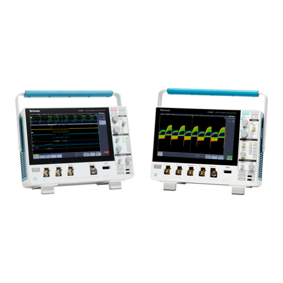
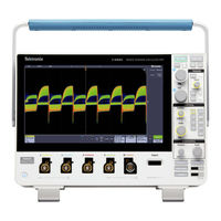
Sign In
Upload
Manuals
Brands
Tektronix Manuals
Test Equipment
MDO34
Tektronix MDO34 Manuals
Manuals and User Guides for Tektronix MDO34. We have
4
Tektronix MDO34 manuals available for free PDF download: Printable Help, Installation And Safety Manual, Quick Start Manual, Declassification And Security Instructions
Tektronix MDO34 Printable Help (282 pages)
Mixed Domain Oscilloscope
Brand:
Tektronix
| Category:
Test Equipment
| Size: 5.48 MB
Table of Contents
Table of Contents
3
List of Figures
10
List of Tables
11
Tektronix End User License Agreement
12
Open Source GPL License Notice
16
GPU Disclosure
17
Welcome to the 3 Series MDO Instrument Help
19
Product Documents and Support
20
Related Documents
20
Product Support and Feedback
20
Accessories
22
Standard Accessories
22
Recommended Accessories
22
Recommended Probes
23
Factory Options
25
Bandwidth Options
25
Digital Channels Option
25
Spectrum Analyzer Frequency Range Options
25
Arbitrary Function Generator (AFG) Option
25
Table 1: 3 Series Bandwidth Options
25
Table 2: 3 Series MSO Option
25
Table 3: 3 Series Spectrum Analyzer Options
25
Enhanced Instrument Security
26
Serial Bus Decode and Trigger Options
26
Power Analysis Option
26
Table 4: 3 Series AFG Option
26
Table 5: Enhanced Instrument Security Pre-Installed Option
26
Table 6: 3 Series Serial Bus Options
26
Table 7: 3 Series Power Option
26
Application Bundle
27
Power Cord Options
27
Service Options
27
Table 8: 3 Series Bundle Option
27
Option Upgrades
29
Post-Purchase Instrument Options
29
Bandwidth Upgrade Options
29
Table 9: Instrument Upgrade Options
29
How to Install an Option License
30
Table 10: MDO32 Bandwidth Upgrades
30
Table 11: MDO34 Bandwidth Upgrades
30
Install Your Instrument
32
Check Shipped Accessories
32
Safely Rotate the Handle
32
Operating Requirements
33
Input Signal Requirements
33
Table 12: Maximum Analog Input
33
Powering the Oscilloscope
34
Table 13: Maximum Input with a P6316 Digital Probe
34
Check that the Oscilloscope Passes Power-On Self Tests
35
Secure (Lock) the Oscilloscope
35
Figure 1: Power Cord Connector and Power Standby Switch
35
Connecting Probes
36
Figure 2: Connecting Probes to the Instrument
36
Rackmount Information
37
Getting Acquainted with Your Instrument
38
Front Panel Controls and Connectors
38
Figure 3: 3 Series MDO Controls
38
Rear Panel Connections
43
The User Interface Screen
44
Identifying Items in the Time Domain Display
45
Identifying Items in the Frequency Domain Display
47
Identifying Items in the Arbitrary Function Generator Display
49
Identifying Items in the Digital Voltmeter Display
49
Badges
50
Configuration Menus
54
Zoom User Interface Elements
55
Using the Touchscreen Interface for Common Tasks
55
Table 14: Common Touchscreen UI Tasks (with Mouse Equivalents)
55
Accessing Application Help
57
Configure the Instrument
58
Set the Date and Time
58
Functional Check
58
Download and Install the Latest Firmware
59
Run Signal Path Compensation (SPC)
59
Compensate TPP0250, TPP0500B, or TPP1000 Probes
60
Compensate Passive Probes
61
Figure 4: Probe Comp Connections
61
Connect to a Network (LAN)
62
Mount a Network Drive
62
Unmount a Network Drive
63
Deskew Analog Input Channels - Quick Visual Method
63
Deskew Analog Input Channels - Measurement Method
64
Connect a Keyboard or Mouse
64
Connect an External Monitor or Projector
65
ESD Prevention Guidelines
65
Analog Channel Operating Basics
66
Acquiring a Signal
66
Quickly Display a Waveform (Autoset)
66
Set Horizontal Parameters
67
How to Trigger on a Signal
67
Set the Acquisition Mode
68
Start and Stop an Acquisition
69
Add a Channel Waveform to the Display
69
Configure Channel or Waveform Settings
70
Add a Math, Reference, or Bus Waveform
71
Add a Measurement
72
Configure a Measurement
74
Delete a Measurement or Search Badge
75
Display an XY Waveform
75
Display an FFT Math Waveform
76
Add a Search
76
Change Waveform View Settings
77
Display and Configure Cursors
78
Using Default Setup
78
Using Fast Acq
79
Remote Access from a Web Browser
80
Connect the Oscilloscope to a PC Using a USB Cable
80
Acquiring Digital Signals
81
Connect and Set up Digital Signals
81
Add a Serial Bus to the Waveform View
82
Add a Parallel Bus to the Waveform View
84
Advanced Triggering
87
Triggering Concepts
87
Trigger on a Pulse Width Event
87
Set Trigger Holdoff
88
Trigger on Sequential Events (a and B Triggers)
89
Set up Trigger on a Parallel Bus
89
Set up Trigger on a Serial Bus
90
Trigger Using the AUX Input
90
Setting Waveform Display Parameters
91
Set the Waveform Persistence Style and Intensity
91
Set the Graticule Style and Intensity
91
Zooming on Waveforms
92
Turn on Zoom Mode
92
Zoom Mode and Searches
92
Customizing Measurements
94
Set Measurement Reference Levels
94
Set Measurement Gates
94
Saving and Recalling Information
96
Save a Screen Image
97
Save a Waveform to a File
97
Save Instrument Settings to a File
98
Save All
98
Recall a Reference Waveform
99
Recall a Setup File
99
Menus and Dialog Boxes
100
The Acquisition Configuration Menu
100
Add Measurements Configuration Menu Overview
101
Amplitude Measurements Panel
102
Time Measurements Panel
104
Other Measurements Panel
105
The Power Measurements Panel (Optional)
106
Measurement Configuration Menu
111
Measurement Name Panel (Measurement Configuration Menu)
111
Global Measurement Settings Panel (Measurement Configuration Menu)
112
Power Measurement Configuration Menu Overview (Optional)
114
Power Measurement Name Panel (Measurement Configuration Menu)
114
SOA Mask Definition Controls and Fields
115
Reference Levels Panel (Power Measurement Configuration Menu)
115
Bus Configuration Menu
115
ARINC429 Serial Bus Menu
117
Audio Serial Bus Configuration Menu
118
CAN Serial Bus Configuration Menu
120
Flexray Serial Bus Configuration Menu
122
I2C Serial Bus Configuration Menu
123
LIN Serial Bus Configuration Menu
124
MIL-STD-1553 Serial Bus Menu
126
Parallel Bus Configuration Menu
127
Parallel Bus - Define Inputs Menu
129
Serial Bus Menu
129
SPI Serial Bus Configuration Menu
131
USB Serial Bus Configuration Menu
132
Add Results Table
134
Search Configuration Menu Overview
135
Bus Search Configuration Menus
135
ARINC429 Serial Bus Search Configuration Menu
136
Audio Serial Bus Search Configuration Menu
138
CAN Serial Bus Search Configuration Menu
139
Flexray Serial Bus Search Configuration Menu
141
I2C Serial Bus Search Configuration Menu
143
LIN Serial Bus Search Configuration Menu
144
MIL-STD-1553 Search Configuration Menu
146
Parallel Bus Search Configuration Menu
148
Serial Bus Search Configuration Menu
149
SPI Serial Bus Search Configuration Menu
149
USB Serial Bus Search Configuration Menu
150
Edge Search Configuration Menu
152
Logic Search Configuration Menu
153
Logic Search - Define Inputs Configuration Menu
155
Pulse Width Search Configuration Menu
155
Rise/Fall Time Search Configuration Menu
156
Runt Search Configuration Menu
158
Setup and Hold Search Configuration Menu
159
Setup and Hold Search - Define Inputs Configuration Menu
160
Timeout Search Configuration Menu
160
Analog Channel Configuration Menu
161
Probe Setup Panel (Channel Configuration Menu)
163
Probe Compensation Configuration Menu (Analog Channels Probe Setup Panel)
163
Other Panel (Channel Configuration Menu)
164
Deskew Configuration Menu (Other Panel Channel Configuration Menu)
164
AFG Configuration Menu
165
Save as Configuration Menu (AFG Menu)
168
RF Configuration Menu
169
Traces Panel (RF Configuration Menu)
169
Horizontal Badge Configuration Menu
170
Spectral Math Configuration Menu
171
Spectral Ref Configuration Menu
171
Cursor Configuration Menu
172
Date and Time Configuration Menu
173
Digital Channel Configuration Menu
173
DVM Configuration Menu
174
Menu Bar Overview
175
Recall Configuration Menu (File Menu)
176
Save as Configuration Menu (File Menu)
177
Print Configuration Menu
180
Add Printer Configuration Menu
180
File Utilities Configuration (File Menu)
181
Mount Network Drive Configuration Menu
182
User Preferences (Utility Menu)
183
I/O (Utility Menu)
184
LAN Reset Configuration Menu (Utility > I O Menu)
186
Self Test Configuration Menu (Utility Menu)
187
Calibration Configuration Menu (Utility Menu)
188
Security Configuration Menu (Utility Menu)
188
Enter Password Configuration Menu (Optional)
189
Table 15: Security Configuration Menu Fields and Controls
189
Set Password Configuration Menu (Optional)
190
Demo (Utility Menu)
191
Help (Help Menu)
191
About (Help Menu)
191
Horizontal Configuration Menu
192
Math Configuration Menu Overview
192
Math Configuration Menu
193
Equation Editor (Math Configuration Menu)
195
Add Functions (Math Equation Editor)
195
Pick Measurement
196
Reference Waveform Configuration Menu
196
Recall Configuration Menu (Ref Waveform Configuration Menu)
197
Search Configuration Menu
198
Trigger Configuration Menu Overview
198
Bus Trigger Configuration
199
ARINC429 Serial Bus Trigger Settings Panel
200
Audio Serial Bus Trigger Settings Panel
201
CAN Serial Bus Trigger Settings Panel
202
Flexray Serial Bus Trigger Settings Panel
204
I2C Serial Bus Trigger Settings Panel
206
LIN Serial Bus Trigger Settings Panel
207
MIL-STD-1553 Serial Bus Trigger Settings Panel
209
Parallel Serial Bus Trigger Settings Panel
211
Serial Bus Trigger Settings Panel
211
SPI Serial Bus Trigger Settings Panel
212
USB Serial Bus Trigger Settings Panel
213
Edge Trigger Configuration Menu
215
Logic Trigger Configuration Menu
216
Logic Trigger - Define Inputs Configuration Menu
218
Pulse Width Trigger Configuration Menu
218
Rise Fall Time Trigger Configuration Menu
219
Runt Trigger Configuration Menu
220
Sequence Trigger Configuration Menu
222
Setup & Hold Trigger Configuration Menu
223
Setup & Hold Trigger - Define Inputs Configuration Menu
224
Timeout Trigger Configuration Menu
224
Video Trigger Configuration Menu
225
Mode and Holdoff Panel
226
Act on Trigger Configuration Menu
227
Viewing the Trigger Frequency
228
Virtual Keyboard
228
Binary, Decimal, Hex, and Octal Virtual Keypads
228
Numeric Input Keypad
229
IP Address Keypad
229
Waveform View Configuration Menu
230
Cursors Menu (RF View)
232
RF Badge Menu
233
Waveform Acquisition Concepts
235
Acquisition Concepts
235
Acquisition Hardware
235
Sampling Process
235
Waveform Record
235
Acquisition Modes
236
How the Acquisition Modes Work
236
Coupling
237
Scaling and Positioning
237
Vertical Acquisition Considerations
237
Horizontal Acquisition Considerations
238
Using Reference Waveforms and Traces
238
Frequency-Domain Concepts
239
Displaying the Frequency Domain Menu
239
RF Waveform View and Badges
239
Spectrum Trace Handle
240
Figure 5: Spectrum Trace Manm Handle Info
240
Spectrum Trace Markers
241
The RF Waveform View User Interface
241
Figure 6: Spectrum Trace Markers
241
Using Spectral Analysis Controls
242
Setting up the RF Input
242
Resolution Bandwidth
243
Spectrogram Display
244
Figure 7: Lower (Narrower) Rbws Take Longer to Process, but Have Finer Frequency Resolution and a Lower Noise Floor
244
Figure 8: Higher (Wider) Rbws Take Less Time to Process, but Have Less Frequency Resolution and a Higher Noise Floor
244
Automatic Peak Markers
245
Frequency Domain Cursors
245
Use the Arbitrary Function Generator
246
Figure 9: the Channel 1 Sine Wave Shows the Output of the AFG. the Channel 2 Square Wave Show the Output of the
248
Triggering Concepts
250
Trigger Sources
250
Trigger Types
250
Trigger Modes
251
Trigger Holdoff
251
Trigger Coupling
252
Trigger Slope and Level
252
Trigger Position in Waveform Record
252
Trigger Delay
252
Bus Triggering Concepts
252
Pulse Width Trigger Concepts
253
Timeout Trigger
253
Runt Trigger
253
Logic Trigger Concepts
253
Setup and Hold Trigger Concepts
253
Rise/Fall Time Trigger Concepts
254
Sequential (a B) Trigger Concepts
254
Waveform Display Concepts
255
Waveform Display Overview
255
Waveform Preview Mode
255
Horizontal Position and the Horizontal Reference Point
255
Annotating the Screen
255
Vertical Graticule Readout
256
Measurement Concepts
257
Taking Automatic Measurements in the Time Domain
257
Taking Automatic Measurements in the Frequency Domain
257
Taking Digital Voltmeter Measurements
257
Taking Manual Measurements with Cursors
258
Making Automated Power Measurements
259
Using Cursor Readouts
260
Using XY Cursors
260
Measurement Variables
260
Missing or Out-Of-Range Samples
262
Math Waveforms
262
Math Waveform Elements
262
Guidelines for Working with Math Waveforms
263
Math Waveform Editor Syntax
263
Math Waveform Differentiation
264
Math Waveform Offset Position and Scale
264
Waveform Integration
264
Using Math Waveforms
265
Using Advanced Math
266
Using FFT
266
FFT Process
267
FFT and Aliasing
267
Blackman-Harris FFT Window Concepts
268
Hanning FFT Window
268
Hamming Window
269
Rectangular Window
269
Using Spectrum Math
269
References
271
Upgrading Firmware
271
Cleaning
271
Index
272
Advertisement
Tektronix MDO34 Installation And Safety Manual (54 pages)
Mixed Domain Oscilloscope
Brand:
Tektronix
| Category:
Test Equipment
| Size: 2.18 MB
Table of Contents
Table of Contents
3
Important Safety Information
5
General Safety Summary
5
Service Safety Summary
7
Terms in the Manual
8
Terms on the Product
8
Symbols on the Product
8
Preface
9
Key Features
9
Related Documents
10
Installing Your Instrument
11
Check Shipped Accessories
11
Safely Rotate the Handle
11
Operating Requirements
12
Input Signal Requirements
12
Secure (Lock) the Oscilloscope
13
Powering the Oscilloscope
14
Check that the Oscilloscope Passes Power-On Self Tests
15
Connecting Probes
15
Rackmount Information
16
Remote Access from a Web Browser
17
Connect the Oscilloscope to a PC Using a USB Cable
17
Cleaning
17
Getting Acquainted with Your Instrument
19
Front Panel Controls and Connectors
19
Rear Panel Connections
25
The User Interface Screen
26
Identifying Items in the Time Domain Display
27
Identifying Items in the Frequency Domain Display
30
Badges
32
Configuration Menus
37
Zoom User Interface Elements
38
Using the Touchscreen Interface for Common Tasks
39
Configure the Instrument
41
Set the Date and Time
41
Download and Install the Latest Firmware
42
Run Signal Path Compensation (SPC)
42
Compensate TPP0250, TPP0500B, or TPP1000 Probes
43
Connect to a Network (LAN)
44
EMC Safety and Environmental Compliance
47
Compliance Information
47
EMC Compliance
47
Safety Compliance
48
Environmental Compliance
49
Tektronix MDO34 Quick Start Manual (39 pages)
3 Series Mixed Domain Oscilloscope
Brand:
Tektronix
| Category:
Test Equipment
| Size: 1.68 MB
Table of Contents
Table of Contents
3
Important Safety Information
4
General Safety Summary
4
Service Safety Summary
6
Terms in this Manual
7
Terms on the Product
7
Symbols on the Product
7
Compliance Information
8
Safety Compliance
8
Environmental Compliance
9
Getting Started
10
Key Features
10
Documentation
10
Check Shipped Accessories
11
Safely Rotate the Handle
11
Operating Requirements
12
Input Signal Requirements
13
Lock the Oscilloscope
14
Powering the Instrument
14
Check that the Oscilloscope Passes Power-On Self Tests
15
Connecting Probes
15
Rackmount Information
16
Remote Access from a Web Browser
16
Connect the Oscilloscope to a PC Using a USB Cable
17
Cleaning
17
Getting Acquainted with Your Instrument
18
Front Panel Controls and Connectors
18
Rear Panel Connections
19
User Interface
20
Identifying Items in the Time Domain Display
21
Identifying Items in the Frequency Domain Display
23
Badges
25
Configuration Menus
29
Zoom User Interface
31
Using the Touchscreen Interface for Common Tasks
32
Configure the Instrument
33
Set the Date and Time
33
Download and Install the Latest Firmware
33
Run Signal Path Compensation (SPC)
34
Compensate TPP0250, TPP0500B, or TPP1000 Probes
34
Connect to a Network (LAN)
36
Index
37
Advertisement
Tektronix MDO34 Declassification And Security Instructions (24 pages)
Mixed Domain Oscilloscope
Brand:
Tektronix
| Category:
Test Equipment
| Size: 0.33 MB
Table of Contents
Table of Contents
5
Preface
7
Memory Devices
11
Volatile Memory Devices
11
Nonvolatile Memory Devices
13
Media and Data Export Devices
14
Clear and Sanitize Procedures
17
Disable the USB Device Port
17
Use the 3-SEC Option to Disable All I/O Ports
17
Disable the LAN Port and Clear the LAN Ethernet Settings
18
Enable the USB Device Port
18
Use the 3-SEC Option to Enable the I/O Ports
19
Enable the LAN Port and Set the LAN Ethernet Settings
19
Built-In Security Features
21
When to Use Teksecure
21
Use Teksecure to Erase Memory Contents
22
Clear or Sanitize a Non-Functional Instrument
23
Acquisition Board
23
USB Flash Drive
23
Charges
23
Advertisement
Related Products
Tektronix MDO3000 Series
Tektronix MDO3104
Tektronix MDO3102
Tektronix MDO3032
Tektronix MDO3024
Tektronix MDO3022
Tektronix MDO3014
Tektronix MDO3012
Tektronix MDO3054
Tektronix MDO3052
Tektronix Categories
Test Equipment
Measuring Instruments
Amplifier
Printer
Portable Generator
More Tektronix Manuals
Login
Sign In
OR
Sign in with Facebook
Sign in with Google
Upload manual
Upload from disk
Upload from URL