Tektronix MDO3000 Series Demonstration Manual
Hide thumbs
Also See for MDO3000 Series:
- Technical reference (125 pages) ,
- Service manual (44 pages) ,
- Instructions manual (26 pages)
Table of Contents
Advertisement
Quick Links
Advertisement
Table of Contents

Related Manuals for Tektronix MDO3000 Series


Summary of Contents for Tektronix MDO3000 Series
- Page 1 Tektronix MDO3000 Series Oscilloscope Demonstration Guide...
- Page 2 www.tektronix.com/mdo3000...
-
Page 3: Table Of Contents
Exercise 5: Using the Integrated Spectrum Analyzer ..34 Powering on the Board ..........8 Exercise 6: Generating Waveforms with the MDO3000 Series Front Panel Overview ......9 Integrated AFG ............... 39 Exercise 1: Capturing Elusive Events with FastAcq ™... -
Page 4: Tektronix Mdo3000 Series Oscilloscope
Oscilloscope 100, 200, 350, 500 MHz and 1 GHz bandwidth models Tektronix MDO3000 Mixed Domain Oscilloscope is the Up to 5 GS/s sampling rate ultimate integrated 6-in-1 oscilloscope that offers a spectrum 10 Mpoint record length on every channel with Wave... - Page 5 MDO3000 Series Oscilloscope Demonstration Guide Spectrum Analyzer – Every MDO3000 ships standard with Protocol Analyzer (Optional) – The MDO3000 Series offers a a dedicated spectrum analyzer input which provides better robust set of tools for debugging serial buses with automatic performance than a traditional oscilloscope FFT.
-
Page 6: About This Guide
This demonstration guide takes you through a series of to power the demo board) with waveforms that represent step-by-step demonstrations on how the MDO3000 Series a number of mixed-signal challenges facing today’s oscilloscope helps simplify the debug of mixed signal designs designers. - Page 7 MDO3000 Series Oscilloscope Demonstration Guide Category Product Description MDO3AERO MIL-STD-1553 serial bus triggering and analysis module MDO3AUDIO Audio serial triggering and analysis module (I S, LJ, RJ, TDM) MDO3AUTO Automotive serial triggering and analysis module (CAN, LIN) Serial Bus MDO3COMP...
-
Page 8: Powering On The Board
MDO3000 Series Oscilloscope Demonstration Guide Powering on the Board To connect and power on the demonstration board, follow these steps: 1. Plug the dual USB A connectors from one end of the “Y” USB cable, which comes with your board, into two USB ports of a PC or an oscilloscope. -
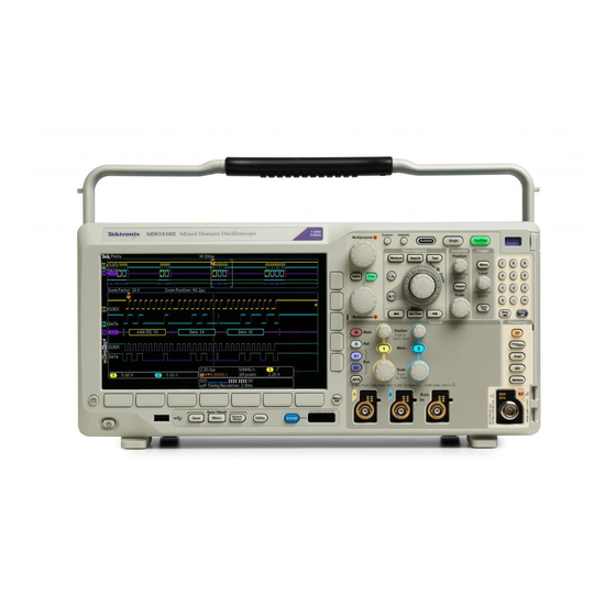
Page 9: Mdo3000 Series Front Panel Overview
MDO3000 Series Oscilloscope Demonstration Guide MDO3000 Series Front Panel Overview www.tektronix.com/mdo3000... -
Page 10: High Waveform Capture Rate
Capturing Elusive Events with FastAcq ™ High Waveform Capture Rate To debug a design problem, first you must know it exists. The MDO3000 Series oscilloscope offers Tektronix proprietary FastAcq technology. It delivers a fast waveform capture – ™ up to 280,000 waveforms per second – that enables you to see glitches and other infrequent transients within seconds, revealing the true nature of device faults. - Page 11 MDO3000 Series Oscilloscope Demonstration Guide 1. Connect a passive probe to channel 1 on the oscilloscope. 2. Connect the ground lead of the probe to the GND point and the probe tip to the RARE_ANOMALY signal on the demonstration board.
- Page 12 MDO3000 Series Oscilloscope Demonstration Guide 4. Press Trigger Menu front panel button. Press Mode Auto & Holdoff lower-bezel button. 5. Turn Multipurpose a to increase holdoff time to 600.0000ns. Figure 4. www.tektronix.com/mdo3000...
- Page 13 MDO3000 Series Oscilloscope Demonstration Guide 6. Press the Acquire front-panel button. 7. Press FastAcq lower-bezel button. Turn on the FastAcq by pressing FastAcq side-bezel button and select On. 8. Press the lower-bezel Waveform Display button. 9. Turn Multipurpose a clockwise to adjust persist time to ∞...
- Page 14 MDO3000 Series Oscilloscope Demonstration Guide Now we see an erroneous runt in the signal. To capture it, follow the steps below. 10. Press the side-bezel Set to Auto button to turn off infinite persistence. 11. Press FastAcq lower-bezel button and then press FastAcq side-bezel button to turn off FastAcq.
-
Page 15: Automated Search
MDO3000 is equal to over 10,000 oscilloscope screens worth of data! To make it easier to find what you are looking for, the MDO3000 Series has a special feature called Wave Inspector which provides tools for quickly moving through long records including an automated search function. - Page 16 MDO3000 Series Oscilloscope Demonstration Guide 1. Connect the channel 1 probe tip to the FREQ_ANOMALY (Frequent Anomalies) signal on the demonstration board. Connect the ground lead of the probe to the GND point. 2. Press the front panel Default Setup button to set the oscilloscope to a known state.
- Page 17 MDO3000 Series Oscilloscope Demonstration Guide Capturing the signal with sufficient detail is critical to successful debugging. For example, if you are interested in how frequent the runt signal occurs, you can acquire a long time window with a long record length and search for runt signals.
- Page 18 MDO3000 Series Oscilloscope Demonstration Guide Now all runts in the acquisition that meet this trigger specification are marked with a hollow white triangle at the top of the display. Notice the number of search events shown in the lower left corner is three.
- Page 19 MDO3000 Series Oscilloscope Demonstration Guide It is very difficult to see much signal detail in this display. If we zoom in on the waveform, the details become visible. 14. Turn the inner Wave Inspector control and notice how the upper window of the display shows the context while the lower window shows the zoomed details.
-
Page 20: Serial Buses
For demonstration purposes all application modules and address, data, identifiers, CRC and so on. options are enabled in MDO3000 demo units. This exercise demonstrates the ability of the MDO3000 Series Note: You can find more serial bus demonstrations in to help you debug I C circuits. - Page 21 MDO3000 Series Oscilloscope Demonstration Guide 1. Connect the ground lead of a probe to a point labeled GND on the demonstration board. Connect the probe from channel 1 on the oscilloscope to the I2C_CLK test point on the demonstration board.
- Page 22 MDO3000 Series Oscilloscope Demonstration Guide 5. Turn the front-panel channel 1 and channel 2 Vertical Scale knobs so that both channel 1 and channel 2 are set to 2.0 V/div. 6. Turn the channel 1 and channel 2 Vertical Position knobs to position channel 1 near the top of the screen and channel 2 near the middle or bottom.
- Page 23 MDO3000 Series Oscilloscope Demonstration Guide 9. Press the lower-bezel Bus B1 button and turn Multipurpose a. Select I2C. 10. Press the lower-bezel Define Inputs button. 11. On the side-menu, confirm that the SCLK Input is set to channel 1 and that the SDA Input is set to channel 2.
- Page 24 MDO3000 Series Oscilloscope Demonstration Guide 12. Press the lower-bezel Thresholds button. 13. Turn multipurpose a and b to set the thresholds at about the midpoint of each waveform. You could also use the presets for common logic family voltages from the Choose Preset side menu.
- Page 25 17. Press the lower-bezel Type button and turn Multipurpose a to the I C bus. select Bus. The MDO3000 Series Oscilloscope triggers on: 18. Press the lower-bezel Trigger On button. Start Notice the list of trigger choices. The key is that you can...
- Page 26 MDO3000 Series Oscilloscope Demonstration Guide 19. Turn Multipurpose a to select Address. 20. Press the lower-bezel Address button. 21. The side-bezel Address button should already be selected. 22. Turn Multipurpose a and b to enter a hex address of 50.
- Page 27 MDO3000 Series Oscilloscope Demonstration Guide 23. Press the lower-bezel Direction button. 24. Select the side-bezel Write button. 25. Press Single to make an acquisition. 26. Press Menu Off. Notice that the oscilloscope now triggers on address 50. Figure 18. www.tektronix.com/mdo3000...
- Page 28 MDO3000 Series Oscilloscope Demonstration Guide In addition to seeing decoded packet data on the bus waveform itself, you can view all captured packets in a tabular view much like you would see in a software listing. Packets are time stamped and listed consecutively with columns for each component (Address, Data, etc.).
- Page 29 MDO3000 Series Oscilloscope Demonstration Guide You can also search for specific values or packets. To search for data value hex 17: 34. Press Search front panel button. 35. Press Search lower-bezel button and turn on search by pressing Search On side-bezel button.
-
Page 30: D/A Converter
Acquiring Analog and Digital signals of a D/A Converter Most embedded systems contain a mix of analog and digital circuitry. MDO3000 Series oscilloscope with its Mixed Signal Oscilloscope capability enables the acquisition of analog and digital signals and displays them time correlated on the display, providing insight into your complete system operation. - Page 31 MDO3000 Series Oscilloscope Demonstration Guide 1. Connect Channel 1 to the DAC_OUT signal on the demonstration board. Connect the ground lead of a probe to a point labeled GND on the demonstration board. 2. Connect the P6316 Logic Probe to the front-panel Logic Probe connector below the oscilloscope display.
- Page 32 MDO3000 Series Oscilloscope Demonstration Guide 4. Press the front-panel Default Setup button. 5. Change the horizontal scale to 4.00ms/div 6. Change the vertical scale of Ch1 to 1.00 V/div 7. Set the trigger level to 50% of Ch1 by pressing the trigger level control knob.
- Page 33 MDO3000 Series Oscilloscope Demonstration Guide 10. Press the blue D15-D0 front-panel button. 11. Press the lower-bezel D15-D0 On/Off button, not the blue D15-D0 front-panel button. 12. Press the side-bezel Turn On D7-D0 button to display channels D0 through 13. Position Ch1 above the digital channels in the upper portion of the display.
-
Page 34: Exercise 5: Using The Integrated Spectrum Analyzer
9 kHz up to the analog bandwidth of the oscilloscope. The input frequency can be upgraded to 9 kHz - 3 GHz on any MDO3000 Series. The following two exercises show you automated markers and spectrogram functionality on the MDO3000. - Page 35 MDO3000 Series Oscilloscope Demonstration Guide A. Multiple Peaks Demonstration This exercise demonstrates how the frequency and amplitude of peaks in the spectrum are quickly identified with automatic peak markers. 1. Attach an N-to-BNC adapter to the RF input on the oscilloscope.
- Page 36 MDO3000 Series Oscilloscope Demonstration Guide 6. Press RF front panel button to turn on the RF channel. 7. Press Freq/Span front-panel button under the spectrum analyzer controls. 8. Use Multipurpose a or the 10-digit keypad to set the center frequency to 2.4 GHz.
- Page 37 MDO3000 Series Oscilloscope Demonstration Guide B. Spectrogram Demonstration 1. Follow step 1 to 3 in the previous 6. Press the R to Center side-bezel button exercise to connect the RF channel to the to set the Center Frequency to the Spectrograms are useful for monitoring demonstration board.
- Page 38 MDO3000 Series Oscilloscope Demonstration Guide 11. Press the Run/Stop front panel button to stop acquiring. 12. Turn the Multipurpose a control to scroll through Spectrum Slices. A Spectrogram shows how the spectrum changes over time. The x-axis is frequency, the y-axis is time.
-
Page 39: Integrated Afg
The MDO3000 Series oscilloscope with the 50 MHz integrated AFG can easily replicate signals acquired by the oscilloscope with added noise or other analog characteristics. - Page 40 MDO3000 Series Oscilloscope Demonstration Guide 1. Connect a BNC cable to Channel 1 and to the AFG output on the rear of the oscilloscope. 2. Connect a passive probe to Channel 2 on the oscilloscope. 3. Connect the ground lead of the probe...
- Page 41 MDO3000 Series Oscilloscope Demonstration Guide 9. Press the Thresholds lower-bezel button and adjust High to approximately 2.00 V using Multipurpose a, adjust Low to about 1.00 V using Multipurpose b. 10. Press the Mode lower-bezel button. Press the Normal side-bezel button.
- Page 42 MDO3000 Series Oscilloscope Demonstration Guide 17. Press the Channel 2 front panel button twice to turn off channel 2 and press the Channel 1 front panel button to turn on channel 1. 18. Press the Run/Stop front panel button to start acquiring the output of the AFG.
-
Page 43: Integrated Dvm
MDO3000 Series Oscilloscope Demonstration Guide Exercise 7 This exercise shows how you can measure DC voltage on a signal over time. Measuring Signals with the Integrated DVM 1. Connect a BNC cable to Channel 1 and to the AFG output on the rear of the oscilloscope. - Page 44 MDO3000 Series Oscilloscope Demonstration Guide 6. Set horizontal scale to 10μs/div. 7. Set Ch1 vertical scale to 200mV/div and use vertical position to center the waveform. 8. Press the Trigger Level control to set the trigger level to 50% of Ch1.
- Page 45 MDO3000 Series Oscilloscope Demonstration Guide 9. Press the Measure front panel button. 10. Press the DVM lower-bezel button to turn on the DVM. 11. Use Multipurpose a to choose DC on Full display. 12. Press Menu Off to remove all menus.
-
Page 46: Locating Signals On Demo Board
MDO3000 Series Oscilloscope Demonstration Guide Locating Signals on Demo Board The following diagram includes a grid to help you locate signal outputs. To find a particular signal output on the board, look up the connector grid location in the following Signal Descriptions section and use the grid location information to find the signal on the demo board. - Page 47 MDO3000 Series Oscilloscope Demonstration Guide DAC Input, Parallel Board label: DAC_IN0, DAC_IN1, DAC_IN2, DAC_IN3, DAC_IN4, DAC_IN5, DAC_IN6, DAC_IN7 Grid location: H3, H4 Description: These signals are the input to the DAC. These are also the 8-bit parallel output signals of the port expander in the middle of the mixed signal chain.
- Page 48 MDO3000 Series Oscilloscope Demonstration Guide Frequent Anomaly C Bus Multiple Peaks Demo Board label: FREQ_ANOMALY Board label: I2C_CLK, I2C_DATA The RF output connector generates an array of frequencies, which are centered around Grid location: A9 Grid location: H2, H3 2.4 GHz, to show the ability of the MDO3000...
- Page 49 MDO3000 Series Oscilloscope Demonstration Guide Rare Anomaly Reset Button RF Output Board label: RARE_ANOM Board label: RESET Board label: None Grid location: A10 Grid location: B7 Grid location: H9 Description: The two less-frequent Description: Press this button to start all...
- Page 50 Specification and price change privileges reserved. TEKTRONIX and TEK are registered trademarks of Tektronix, Inc. All other trade names referenced are the service marks, trademarks or registered trademarks of their respective companies.
Need help?
Do you have a question about the MDO3000 Series and is the answer not in the manual?
Questions and answers