
Related Manuals for Huawei SMU01C


Summary of Contents for Huawei SMU01C
- Page 1 SMU01C V300R002C03 User Manual Issue Date 2015-01-05 HUAWEI TECHNOLOGIES CO., LTD.
- Page 2 Notice The purchased products, services and features are stipulated by the contract made between Huawei and the customer. All or part of the products, services and features described in this document may not be within the purchase scope or the usage scope. Unless otherwise specified in the contract, all statements, information, and recommendations in this document are provided "AS IS"...
-
Page 3: About This Document
SMU01C User Manual About This Document About This Document Purpose This document describes the SMU01C in terms of its modules, panels, ports, liquid crystal display (LCD), operations, installation, and troubleshooting. Intended Audience This document is intended for: Sales engineers ... - Page 4 Updated Table 9-1 Alarm list to optimize alarm names. Updated Table A-1 LCD menu to add the OLE Charger function. The matching software version is V300R002C03SP08. Issue 01 (2013-04-15) The matching software version is V300R002C03SP03. Issue 03 (2015-01-05) Huawei Proprietary and Confidential Copyright © Huawei Technologies Co., Ltd.
-
Page 5: Table Of Contents
1.4 Functions ................................2 2 Panel and Ports ..........................4 3 Installation............................7 3.1 Installing an SMU01C ............................7 3.2 Installing Dry Contacts and Boolean Values Signal Cables ................8 4 LCD Operations..........................9 5 Power System Configuration ....................12 5.1 Basic Lead-Acid Battery Parameters ...................... - Page 6 9.5.19 Batt Off ............................... 40 9.5.20 Load Off .............................. 40 10 Troubleshooting ........................41 A LCD menu ........................... 42 B Technical Specifications ......................46 C Acronyms and Abbreviations ....................48 Issue 03 (2015-01-05) Huawei Proprietary and Confidential Copyright © Huawei Technologies Co., Ltd.
-
Page 7: Overview
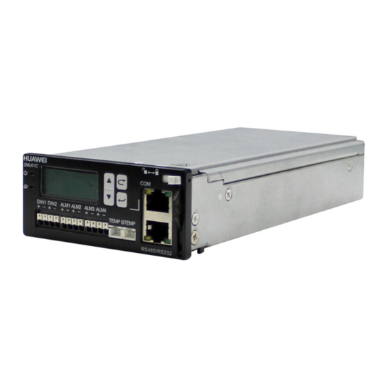
User Manual 1 Overview Overview 1.1 Appearance The SMU01C is a site power monitoring module that monitors Huawei box-type power modules. Figure 1-1 shows an SMU01C. Figure 1-1 SMU01C 1.2 Network Diagrams The SMU01C manages batteries and rectifiers, and monitors the operating environment for the power system according to the ambient temperature and battery temperature displayed on the liquid crystal display (LCD). -
Page 8: Features
Provides ports for battery temperature sensors and ambient temperature sensors. Supports Chinese and English as displayed languages. Is hot-swappable. 1.4 Functions Table 1-1 shows the main functions of the SMU01C. Table 1-1 SMU01C functions Category Function Battery management Battery boost charging and float charging management... - Page 9 Rectifier power-on/off control Rectifier output voltage and current limiting Energy saving Intelligent rectifier hibernation Detection AC voltage DC voltage Load current Battery current and temperature Ambient temperature Issue 03 (2015-01-05) Huawei Proprietary and Confidential Copyright © Huawei Technologies Co., Ltd...
-
Page 10: Panel And Ports
User Manual 2 Panel and Ports Panel and Ports Panel All ports in this manual are protected by a security mechanism. Figure 2-1 shows an SMU01C panel. Figure 2-1 SMU01C panel (1) Run indicator (2) Major alarm indicator (3) LCD... - Page 11 Steady on A major alarm is generated. indicator The SMU01C provides a liquid crystal display (LCD) to display power system information in real time. Buttons The SMU01C provides four buttons for setting and querying parameters. Table 2-2 describes the buttons.
- Page 12 Table 2-4 COM or RS485/RS232 port pin definition Signal Description Sends data over RS485. Receives data over RS485. RX232 Receives data over RS232. TX232 Sends data over RS232. PGND Ground Issue 03 (2015-01-05) Huawei Proprietary and Confidential Copyright © Huawei Technologies Co., Ltd...
-
Page 13: Installation
3.1 Installing an SMU01C To install an SMU01C, perform the following steps: Step 1 Hold the handle of the SMU01C, and insert the SMU01C into the correct position in the power system. Step 2 Push the SMU01C until its front panel aligns with the front panel of the power subrack. -
Page 14: Installing Dry Contacts And Boolean Values Signal Cables
Install dry contacts and Boolean values signal cables, as shown in Figure 3-2. Figure 3-2 Installing dry contacts and boolean values signal cables (1) White Contact plate (2) Dry contact Issue 03 (2015-01-05) Huawei Proprietary and Confidential Copyright © Huawei Technologies Co., Ltd... -
Page 15: Lcd Operations
Before entering Setting and Maintenance, you need to enter a password. The preset password is 000001. Symbol Description Table 4-1 Symbol Description Symbol Description Press the Enter button once. Press the Down button once. Press the Down button more than once. Issue 03 (2015-01-05) Huawei Proprietary and Confidential Copyright © Huawei Technologies Co., Ltd... - Page 16 Picture bordered in red shows parameters and values. Display Language After powering on the SMU01C, select English by pressing ▲ or ▼ on the LCD, and then press Enter to enter the standby screen. Figure 4-2 Selecting a display language Viewing System Operating Information You can view real-time information about the AC and DC status and load current on the LCD.
- Page 17 Step 5 On the Enter New PSW page, press ▲ or ▼ to specify a new password and then press Enter. Figure 4-4 Changing user password ----End Issue 03 (2015-01-05) Huawei Proprietary and Confidential Copyright © Huawei Technologies Co., Ltd...
-
Page 18: Power System Configuration
Examples: If the battery capacity is 100 Ah and the maximum charging current is 10 A, set the charge coefficient to 0.10. Issue 03 (2015-01-05) Huawei Proprietary and Confidential Copyright © Huawei Technologies Co., Ltd... -
Page 19: Communications Parameters
5 Power System Configuration LCD Operation Figure 5-1 Setting basic battery parameters on the LCD 5.2 Communications Parameters Principles You can manage the SMU01C locally and remotely over the RS4985, RS232 and COM ports. Table 5-2 Communications parameters Network Port Parameter... - Page 20 SMU01C SMU01C automatically LCD Operation Figure 5-2 Setting communications parameters on the LCD The SMU01C automatically identifies Baud. Values in the preceding figure are for reference only. Issue 03 (2015-01-05) Huawei Proprietary and Confidential Copyright © Huawei Technologies Co., Ltd...
-
Page 21: Vrla Battery Management
Description Default Value Value Range The voltage at which FC Volt 53.5 V 47.0 V–56.5 V VRLA batteries are ≤ Boost charge charged in float voltage mode. Issue 03 (2015-01-05) Huawei Proprietary and Confidential Copyright © Huawei Technologies Co., Ltd... -
Page 22: Boost Charging
53.5 V to 57.0 V which lead-acid > Float charge batteries are being voltage charged in boost < DC mode overvoltage threshold: – 1 V Issue 03 (2015-01-05) Huawei Proprietary and Confidential Copyright © Huawei Technologies Co., Ltd... -
Page 23: Low Voltage Disconnection Protection
6.2 Low Voltage Disconnection Protection Principles If an AC input is abnormal, batteries start to power loads. In this case, the SMU01C drives contactors to disconnect loads and batteries in sequence based on preset disconnection parameters. After the AC input resumes, the rectifiers begin to power loads and charge batteries. - Page 24 44.0 V 38.0 V to 44.9 V is lower than the BLVD Volt to DC value of LLVD Under Volt voltage threshold, the LLVD circuit is disconnected. Issue 03 (2015-01-05) Huawei Proprietary and Confidential Copyright © Huawei Technologies Co., Ltd...
- Page 25 SMU01C User Manual 6 VRLA Battery Management LCD Operation Figure 6-3 BLVD low voltage disconnection setting on the LCD Issue 03 (2015-01-05) Huawei Proprietary and Confidential Copyright © Huawei Technologies Co., Ltd...
- Page 26 SMU01C User Manual 6 VRLA Battery Management Figure 6-4 LLVD low voltage disconnection setting on the LCD Issue 03 (2015-01-05) Huawei Proprietary and Confidential Copyright © Huawei Technologies Co., Ltd...
-
Page 27: Rectifier Management
SMU01C User Manual 7 Rectifier Management Rectifier Management 7.1 Querying Operating Information Principles The SMU01C monitors the rectifier operating information in real time and displays the information on the LCD. Parameters Table 7-1 Rectifier operating information Parameters Description DC output voltage... -
Page 28: Setting Intelligent Hibernation Parameters
2 hours and then hibernate certain rectifiers. Issue 03 (2015-01-05) Huawei Proprietary and Confidential Copyright © Huawei Technologies Co., Ltd... - Page 29 Exch Cycle Interval between 7 days 5 to 30 days hibernation operations Minimum number of Min Num Rect 1 PCS 1 to 5 PCS running rectifiers Issue 03 (2015-01-05) Huawei Proprietary and Confidential Copyright © Huawei Technologies Co., Ltd...
- Page 30 SMU01C User Manual 7 Rectifier Management LCD Operation Figure 7-3 Setting parameters for intelligent rectifier hibernation on the LCD Issue 03 (2015-01-05) Huawei Proprietary and Confidential Copyright © Huawei Technologies Co., Ltd...
-
Page 31: Maintenance
You can view the current monitoring software version on the LCD by choosing Main Menu > Alarm & Status > Version Info. Figure 8-1 SMU01C version information on the LCD 8.2 Setting Time and Date Figure 8-2 shows how to set time and date on the LCD. -
Page 32: Setting The System Type
Figure 8-3 shows how to set the system type on the LCD. The default system type varies based on the subrack types. The following figure takes the EPT4890 as an example. Issue 03 (2015-01-05) Huawei Proprietary and Confidential Copyright © Huawei Technologies Co., Ltd... - Page 33 SMU01C User Manual 8 Maintenance Figure 8-3 Setting system type on the LCD Issue 03 (2015-01-05) Huawei Proprietary and Confidential Copyright © Huawei Technologies Co., Ltd...
-
Page 34: Alarm Management
User Manual 9 Alarm Management Alarm Management 9.1 Alarm Setting Table 9-1 lists alarms for the SMU01C. You can set the alarm dry contact input port, alarm severity, alarm dry contact output port. Table 9-1 Alarm list Alarm Default Alarm Severity... -
Page 35: Setting Alarm Severity
None ALM2 9.1.2 Setting Alarm Severity Figure 9-1 shows the default severities for alarms about the SMU01C. You can modify the alarm severity on the LCD, as shown in Figure 9-1 (modifying the alarm severity for Batt Over Temp alarm). -
Page 36: Associating Alarms To Dry Contact Input Ports
The following example describes how to connect a heater to the DIN2 port. Step 1 Figure 9-2 shows how to connect the SMU01C to a heater. For connecting the signal cables between the SMU01C and the heater, see Figure 9-2. Issue 03 (2015-01-05) Huawei Proprietary and Confidential Copyright ©... - Page 37 Figure 9-2 Connecting the SMU01C to a heater Step 2 Read the heater instruction to check whether the dry contact status when alarms are generated matches the default dry contact status for the SMU01C. Table 9-1 shows the default configuration for the SMU01C dry contact input ports.
-
Page 38: Associating Alarms To Dry Contact Output Ports
----End 9.1.4 Associating Alarms to Dry Contact Output Ports The SMU01C provides four dry contact outputs that relate to the alarms in Table 9-1. Table 9-2 lists the default dry contact output configurations. You can modify the configurations as required. -
Page 39: Viewing Active Alarms
Figure 9-4 Associating alarms to dry contact output ports 9.2 Viewing Active Alarms You can view active alarms on the LCD, as shown in Figure 9-5. Parameters in the figure are for reference only. Issue 03 (2015-01-05) Huawei Proprietary and Confidential Copyright © Huawei Technologies Co., Ltd... -
Page 40: Viewing Historical Alarms
Figure 9-6 shows how to view the historical alarms on the LCD. Parameters in the figure are for reference only. Figure 9-6 Viewing historical alarms Issue 03 (2015-01-05) Huawei Proprietary and Confidential Copyright © Huawei Technologies Co., Ltd... -
Page 41: Deleting Historical Alarms
9.5.2 AC Over Volt Possible Causes The AC voltage exceeds the alarm threshold. The AC overvoltage alarm threshold is not properly set on the monitoring unit. Issue 03 (2015-01-05) Huawei Proprietary and Confidential Copyright © Huawei Technologies Co., Ltd... -
Page 42: Ac Under Volt
The alarm is automatically cleared after the AC input restores. If the Fault indicator on a rectifier is steady on, replace the rectifier. Adjust the DC undervoltage alarm threshold to a proper range. Issue 03 (2015-01-05) Huawei Proprietary and Confidential Copyright © Huawei Technologies Co., Ltd... -
Page 43: Batt Over Temp
Replace the faulty temperature sensor. 9.5.9 Amb.Under Temp Possible Causes Ambient temperature alarm threshold is not properly set on the monitoring unit. The temperature sensor is faulty. Issue 03 (2015-01-05) Huawei Proprietary and Confidential Copyright © Huawei Technologies Co., Ltd... -
Page 44: Batt Operation
If the alarm persists after the load circuit breaker is replaced, replace the monitoring unit because the alarm loop is faulty. 9.5.13 Batt. loop Trip Possible Causes The battery circuit breaker is OFF. Issue 03 (2015-01-05) Huawei Proprietary and Confidential Copyright © Huawei Technologies Co., Ltd... -
Page 45: Rect Fault
9.5.17 Rect Comm Fault Possible Causes The signal cable to the rectifier is not connected properly. The rectifier is removed. The rectifier is in poor contact. Issue 03 (2015-01-05) Huawei Proprietary and Confidential Copyright © Huawei Technologies Co., Ltd... -
Page 46: Rect Protect
The ambient temperature exceeds the upper threshold. Measures If the AC input power is unavailable, recover the AC power supply. If the ambient temperature is higher than the upper threshold, decrease the temperature. Issue 03 (2015-01-05) Huawei Proprietary and Confidential Copyright © Huawei Technologies Co., Ltd... -
Page 47: Troubleshooting
SMU01C User Manual 10 Troubleshooting Troubleshooting Table 10-1 describes the common faults and troubleshooting measures for the SMU01C. Table 10-1 Common SMU01C faults and troubleshooting measures Symptom Possible Cause Measures The major alarm indicator A major alarm is generated. Rectify faults based on the (red) is steady on. -
Page 48: A Lcd Menu
(FC Volt ≤ BC Volt ≤ DC Over Volt – 1 V) Over Volt 58.0V 58.0 V–60.0 V Under Volt 45.0V 43.1 V–51.5 V (LLVD Volt ≤ Issue 03 (2015-01-05) Huawei Proprietary and Confidential Copyright © Huawei Technologies Co., Ltd... - Page 49 Min Num Rect 1pcs 1 pcs–5 pcs Load HT Off LHTD Enable Yes, No Load Off Temp 70° C 50° C–80° C Rect Off Time 240Min 1–255 Min Issue 03 (2015-01-05) Huawei Proprietary and Confidential Copyright © Huawei Technologies Co., Ltd...
- Page 50 8-20 A Duration 24 h 12–48 h BC Volt 56.5 V 53.5-58.0 V FC Volt 53.5 V 46.0–56.5 V OLE Charger Yes, No Maintenance Start BC/FC FC, BC Issue 03 (2015-01-05) Huawei Proprietary and Confidential Copyright © Huawei Technologies Co., Ltd...
- Page 51 SMU01C User Manual A LCD menu Second-Level Third-Level Fourth-Level Main Menu Default Value Range Menu Menu Menu CLR History Yes, No Issue 03 (2015-01-05) Huawei Proprietary and Confidential Copyright © Huawei Technologies Co., Ltd...
-
Page 52: B Technical Specifications
Signal port 3 V (criterion A) IEC61000-4-3 10 V/m (criterion A) IEC61000-4-2 Contact discharge: 6 kV (criterion B) Air discharge: 8 kV (criterion B) Contact discharge: 8 kV (criterion R) Issue 03 (2015-01-05) Huawei Proprietary and Confidential Copyright © Huawei Technologies Co., Ltd... - Page 53 SMU01C User Manual B Technical Specifications Category Item Specifications Air discharge: 15 kV (criterion R) ≥ 250,000 hours MTBF Issue 03 (2015-01-05) Huawei Proprietary and Confidential Copyright © Huawei Technologies Co., Ltd...
-
Page 54: C Acronyms And Abbreviations
SMU01C User Manual C Acronyms and Abbreviations Acronyms and Abbreviations liquid crystal display site monitoring unit Issue 03 (2015-01-05) Huawei Proprietary and Confidential Copyright © Huawei Technologies Co., Ltd...
Need help?
Do you have a question about the SMU01C and is the answer not in the manual?
Questions and answers