Advertisement
Quick Links
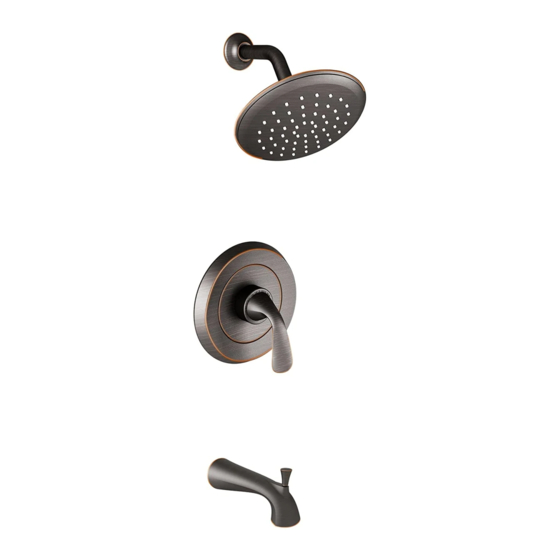
FLUENT™
PRESSURE BALANCING
BATH AND SHOWER
TRIM KITS
Thank you for selecting American-Standard...the benchmark of fine
quality for over 100 years.
To ensure that your installation proceeds smoothly-- please read these
instructions carefully before you begin.
RECOMMENDED TOOLS
Plumbers' Putty or Caulking
ROUGHING-IN DIMENSIONS (For reference only)
To assure proper positioning in relation to wall, note roughing-in dimensions.
2-7/32" D.
(57mm)
5" REF.
(127mm)
8-1/2" REF.
(216mm)
3-3/4" REF.
(95mm)
7-1/2" REF.
(191mm)
FINISHED
WALL
"SEE ILLUSTRATION "
74" FOR HEAD
CLEARANCE
(1880mm)
18" OPTIONAL
(457mm)
1-3/4"
(44 mm)
6-19/32" REF.
(167mm)
TOP OF TUB RIM
BOTTOM OF TUB
Installation
Instructions
T186.500
T186.501
T186.502
T186.507
T186.508
Phillips Screwdriver
Teflon Tape
Flat Blade Screwdriver
SHR. 1/2" NOM. (13mm)
1-7/8" to 3-1/4"
(48 to 83 mm)
TUB 1/2" (13mm) NOM.
1/2" NPT
(13mm)
OPTIONAL TO FINISHED
FLOOR USUALLY
BETWEEN 65'' AND 80''
(1651 and 2032mm)'
8" DIA.
(204mm)
3-3/8"
(86mm)
OUTLETS
1/2" NPT
(13mm)
1/2" COPPER
4" (102mm)
Adjustable Wrench
INLETS
4-1/16"
(103mm)
COPPER SWEAT
SWEAT
INLETS
COPPER SWEAT
SHR. 1/2" NOM.(13mm)
COPPER SWEAT
TUB 1/2" NOM. (13mm)
COPPER SWEAT
INLETS 1/2" NPT (13mm}
3-3/8"
(86mm)
3-3/8"
(86mm)
THREADED INLETS
H
O f f
C
507/508
500/501/502
Certified to comply with ANSI A112.18.1
M965625 REV. 1.1 (11/14)
Slip Jaw Pliers
INLETS
1/2" NOM. (13mm)
COPPER
SWEAT
2"
4-1/16"
(103mm)
SWEAT
INLETS (STOPS)
5-7/8"
(149mm)
4-1/16"
(103mm)
INLETS
1/2" NOM.
(13mm)
COPPER
SWEAT
OUTLETS
1/2" NPT
(13mm)
5-7/8"
(149mm)
THREADED INLETS (STOPS)
THREADED INLETS (STOPS)
H
O f f
C
INLETS
1/2" NPT
(13mm)
Advertisement

Subscribe to Our Youtube Channel
Related Manuals for American Standard FLUENT T186.501


Summary of Contents for American Standard FLUENT T186.501
- Page 1 Installation Instructions FLUENT™ T186.500 PRESSURE BALANCING T186.501 BATH AND SHOWER T186.502 O f f O f f TRIM KITS T186.507 T186.508 Thank you for selecting American-Standard...the benchmark of fine 507/508 500/501/502 quality for over 100 years. To ensure that your installation proceeds smoothly-- please read these Certified to comply with ANSI A112.18.1 instructions carefully before you begin.
- Page 2 INSTALL VALVE TRIM Figure 1. Remove plaster guard from valve. Push CAP (1) over VALVE CARTRIDGE (2) until seated against stop. PLSTER GUARD Figure 2. Push ESCUTCHEON (3) onto CAP (1). Align mounting holes in ESCUTCHEON (3) with valve body. Attach to valve body with LONG SCREWS (4).
- Page 3 ADJUST HOT LIMIT STOP By restricting HANDLE rotation and limiting the amount of hot water allowed to mix with the cold, the HOT LIMIT SAFETY STOP (1) reduces risk of accidental scalding. To set the maximum hot water temperature of your faucet, all you need to do is adjust the setting on the HOT LIMIT SAFETY STOP (1).
- Page 4 FLUENT™ PRESSURE BALANCE BATH/SHOWER MODEL NUMBER T186.500 T186.501 060337-YYY0A SHOWER ARM A919542-YYY0A T186.502 FLANGE SHOWER ARM T186.507 T186.508 1660604.XXX SHOWER HEAD M907050-YYY0A 1660717.XXX ESCUTCHEON CAP SHOWER HEAD M909349-YYY0A DIAL PLATE M918039-0070A M907813-YYY0A HANDLE ADAPTER ESCUTCHEON KIT M964928-YYY0A LEVER HANDLE KIT 078016-YYY0A ESCUTCHEON SCREWS A918477-0070A...
Need help?
Do you have a question about the FLUENT T186.501 and is the answer not in the manual?
Questions and answers