Table of Contents
Advertisement
Quick Links
Instruction Leaflet IL157002EN
Eaton BLR-ACX
Quick commissioning guide
Effective July 2019
Contents
Description
Screen legends . . . . . . . . . . . . . . . . . . . . . . . . . . . 2
Operation . . . . . . . . . . . . . . . . . . . . . . . . . . . . . . . 2
Commissioning . . . . . . . . . . . . . . . . . . . . . . . . . . . 2
Overview . . . . . . . . . . . . . . . . . . . . . . . . . . . . . . . 3
Menu structure . . . . . . . . . . . . . . . . . . . . . . . . . . . 5
Troubleshooting . . . . . . . . . . . . . . . . . . . . . . . . . . 6
BLR-ACX controller . . . . . . . . . . . . . . . . . . . . . . . . 7
Page
Advertisement
Table of Contents

Related Manuals for Eaton BLR-ACX


Summary of Contents for Eaton BLR-ACX
-
Page 1: Table Of Contents
BLR-ACX controller . . . . . . . . . . . . . . . . . . . -
Page 2: Screen Legends
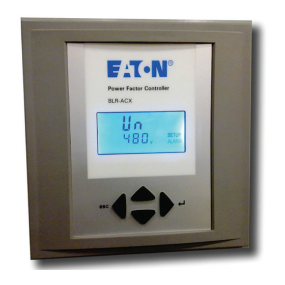
Capacitor stage number indication Figure 1. Digital display Operation Commissioning Operation of BLR-ACX is done by 4 keys . Step 1 Upon power on the controller displays the existing power factor value “X.XX i” and enters the Automatic Control mode. -
Page 3: Overview
Step 4 The final step in commissioning is to verify the working of the BLR-ACX is factory preset to the default values shown in Table 1 . capacitor bank . This is done by activating the controller in manual Customer to program and verify the values set to meet the specific control mode and cycling through all the available steps . - Page 4 Instruction Leaflet IL157002EN Eaton BLR-ACX Quick commissioning guide Effective July 2019 Measurement Mode U Voltage ULL (V) ▼ U Voltage ULN (V) ▼ I Current (A) ▼ P active power (W) ▼ Main screen Q reactive power (VAR) ▼ ∆ Q reactive power to target ▼...
-
Page 5: Menu Structure
Menu structure The following table provides an overview about the basic and advanced programming parameters of BLR-ACX . Menu 100 is the Basic Menu . Menu 200 through 600 is for advanced users only and requires a PIN access (242) . The settings in these submenus should only be accessed and changed after consulting with Eaton Table 1. -
Page 6: Troubleshooting
Instruction Leaflet IL157002EN Eaton BLR-ACX Quick commissioning guide Effective July 2019 Troubleshooting The allowed range of voltage depends on nominal voltage . When nominal voltage is out of range, “U Alarm” is shown . If this alarm is seen, then the setting of nominal voltage has to be adjusted . -
Page 7: Retrofit Installations With
3 . Connect protection GROUND to PE connection of metal case . 1 . Check that CT and PT ratios are programmed correctly in 4 . BLR-ACX is to be connected according to the wiring diagram . Menu 100 . - Page 8 1000 Eaton Boulevard Cleveland, OH 44122 United States Eaton .com © 2019 Eaton All Rights Reserved Eaton is a registered trademark. Printed in USA All other trademarks are property Publication No . IL157002EN / Z23003 July 2019 of their respective owners.
Need help?
Do you have a question about the BLR-ACX and is the answer not in the manual?
Questions and answers