Advertisement
Cutler-Hammer
Installation and Maintenance Manual
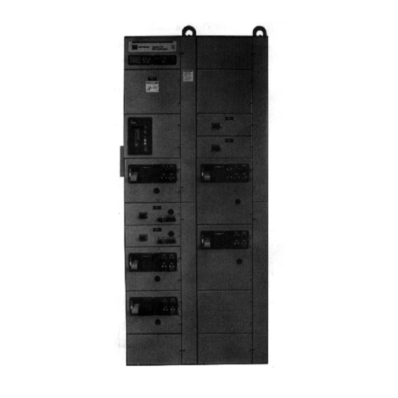
Motor Control Center
PART DESCRIPTION
1
2
3
4
5
6
7
8
9
10
11
12
This electrical control equipment is designed to be in-
stalled, operated, and maintained by adequately trained
workmen. These instructions do not cover ll details, vari-
ations, or combinations of the equipment, its storage,
delivery, installation, check-out, safe operation, or main-
tenance. Care must be exercised to comply with local,
state, and national regulations, as well as safety prac-
tices, for this class of equipment. The maximum short
circuit capability of the equipment should not be ex-
ceeded by connection to a source with higher capacity.
If maintenance or troubleshooting assistance is required,
contact your nearest Westinghouse Engineering Serv-
ice Division or Sales Office.
- Page 1 -
Instruction Book
Effective 12/94
TABLE OF CONTENTS
Model A
PAGE
2
4
5
10
12
14
16
18
19
23
30
31
I.B. 8926-1
Advertisement
Table of Contents

Related Manuals for Eaton Freedom 2100


Summary of Contents for Eaton Freedom 2100
-
Page 1: Table Of Contents
Instruction Book I.B. 8926-1 Cutler-Hammer Model A Effective 12/94 Freedom 2100 Motor Control Center Installation and Maintenance Manual TABLE OF CONTENTS PART DESCRIPTION PAGE General Information Receiving, Handling & Storage Installing Control Center Sections Installing Conduit & Wiring Incoming Line Connections... -
Page 2: 8926-1
The Each vertical section provides space to mount up to six Freedom 2100 MCC may be joined to existing Cutler- controller units (2) with a minimum height of 12 inches, Hammer Freedom Unitrol and Fl 0 Unitrol MCC’s with a in increments of six inches, for a total of 72 inches of special splice bar kit, but units are not interchangable. - Page 3 Fig. 2 Motor control Center Nomenclature will accommodate up to six pilot devices. The overload Space for a minimum of three padlocks is provided on reset button (20) is mounted on the unit door. each handle. The device panel (6) is mounted on the drawout unit. It - Page 3 - I.B.
-
Page 4: Receiving, Handling & Storage
RATINGS QUALIFIED PERSONNEL Each Freedom 2100 Motor Control Center has a rating Individuals who install, operate or maintain motor con- nameplate attached to the door of the top horizontal trol centers must be trained and authorized to operate wireway of the primary section. -
Page 5: Installing Control Center Sections
vent tipping. STORAGE When a motor control center cannot be installed and placed into operation immediately upon receipt, take steps to prevent damage by condensation or harsh en- vironmental conditions. If the motor control center can- not be installed in its final location, store it in a clean, dry, ventilated building, heated to prevent condensation, and protected from dirt, dust, water, and mechanical Fig. - Page 6 mounted on a level surface. The foundation furnished by the purchaser must be true and level, or the bottom frames must be shimmed to support the entire base in a true plane. It is recom- mended that leveled channel sills under both the front and rear of the control center be used to provide this level base.
- Page 7 3. Remove the upper horizontal wireway door from the i) Run a grounding electrode conduc- structure on the right side of the left-hand (LH) sec- tor (ground wire) having a size in ac- tion and remove the two-piece wireway barrier to cordance with NEC 250-94 from the provide access to the ends of the bus in that sec- grounding electrode to the MCC...
- Page 8 ate quantities of related hardware. For a single bus bar per phase the hardware is used as shown in Figure 6 for either 16" or 20" deep enclosures. Eachsplice plate is punched with rectangular holes to accept a square shank carriage bolt that will not rotate as the nut is tightened.
- Page 9 TYPE 3R ENCLOSURES Where the MCC is supplied in a Type 3R enclosure for an outdoor application, apply roof splice caps at each shipping block junction to maintain the enclosure integrity. Fig. 9 Quadruple Bar Splice Kits Fig. 10 Six and Eight Bar Splice Kits - Page 9 - I.B.
- Page 10 JOINING FREEDOM 2100 TO FREEDOM UNITROL OF F10 UNITROL Consult the assembly instructins supplied with every Freedom 2100 Motor Control Center set up for splice to Freedom Unitrol of F10 Unitrol. Fig. 11 Splice Plates Attached to Freedom 2100 Fig. 12 Horizontal bus Splice Freedom unitrol On Left, - Horizontal bus and Ground Bus at Top.
-
Page 11: Installing Conduit & Wiring
PART 4 INSTALLING CONDUIT AND WIRING CONDUIT Use care in stripping insulation to avoid nicking or ring- Install conduit in such a manner as to prevent water from ing the metal. entering and accumulating in the conduit or the enclo- sure. - Page 12 accept the blade of an electrician’s screwdriver used to NEMA TYPE C WIRING cam the block into and out of engagement. Each male Each control unit is factory assembled with device interwired within the unit. In addition, all control wiring i carried to unit terminal blocks on the side of the unit and from these unit blocks, along with load wiring through Size 3, to master terminal blocks located at the top o...
-
Page 13: Incoming Line Connections
PART 5 INCOMING LINE CONNECTIONS OVERCURRENT PROTECTION All ungrounded conductors in a motor control center (MCC) installation require some form of overcurrent pro- tection in order to comply with Section 240-20 of the NEC. Such overcurrent protection for the incoming lines to the MCC is in the form of fuses or a circuit breaker located at the transformer secondary that supplies the MCC. - Page 14 circuit breaker or the load side of the fuses associated with the circuit interrupter has already been connected to the MCC bus bar distribution system. In the case of main disconnects rated 400 amperes or less, this load connection is made by stab connections to vertical bus bars which connect to the horizontal bus distribution sys- tem.
-
Page 15: Overcurrent Protection Devices
PART 6 OVERCURRENT PROTECTION DEVICES DEVICE SELECTION Articles 240 and 430 of the NEC contain the rules for selecting fuses, circuit breakers and overload relays by type and by voltage and ampere rating. Follow these rules for feeder circuits, and the instructions attached to the inside of the left-most vertical wireway door, for mo- tor branch circuits. - Page 16 times motor full-load amperes to prevent tripping when CURRENT TRANSFORMERS starting. When current transformers are used with overload re- A cam to accept a small narrow-blade electrician’s screw- lays, the current through the overload relay heater is re- driver is near the lower left corner and around which are lated to the motor full-load by the inverse of the current eight lettered adjustment points, calibrated in trip am- transformer ratio.
-
Page 17: Overload Relay Heater Selection
PART 7 OVERLOAD RELAY HEATER SELECTION HEATER SELECTION AND INSTALLATION C. Adjust the FLA adjustment dial to the motor name- plate FLA (full load amps). Heaters should be selected on the basis of the actual full load current and service factor as shown on the mo- THE OVERLOAD IS NOW tor nameplate or in the motor manufacturer’s published SET FOR 1.15 SERVICE... - Page 18 FLA DIAL ADJUSTMENT - For motors having a 1.15 WARNING - To provide continued protection against fire service factor, rotate the FLA adjustment dial to corre- or shock hazard, the complete overload relay must be spond to the motor’s FLA rating. Estimate the dial posi- replaced if burnout of the heater element occurs.
- Page 19 NEMA SIZE 5 HEATER PACK SELECTION TABLE MOTOR FLA RATING TRIP CLASS FLA DIAL POSITIONS H2003B H2004B H2005B H2006B H2007B — H2008B MAXIMUM RATINGS NEMA Size 5 = 270 Amperes Min. Wire Size - 2 AWG NEMA SIZE 6 HEATER PACK SELECTION TABLE MOTOR FLA RATING TRIP CLASS...
-
Page 20: Inspection Prior To Energizing
PART 8 INSPECTION PRIOR TO ENERGIZING 1. Before energizing the motor control center (MCC), conduct a thorough inspection to make certain that all foreign materials such as tools, scraps of wire and other debris are removed from all units and the structure. -
Page 21: Unit Installation & Adjustment
PART 9 UNIT INSTALLATION AND ADJUSTMENT DOOR REMOVAL AND INSTALLATION All doors on the control center are mounted on pin hinges to facilitate removal for installation and maintenance op- erations. With the operating handle in the OFF position, rotate the quarter-turn latches, open the door, remove the hinge pins as shown in Figure 26, partially close the door and lift it from the structure. - Page 22 DETENT POSITION For maintenance and test purposes, the unit can be par- tially withdrawn (approximately 1 inches) until the stabs are free of the bus. In this position, the quarter-turn latch can be rotated clockwise to engage the detent position slot;...
- Page 23 CAUTION: Brace the panel solidly to avoid breaking INSTALLING A NEW UNIT the hinge points. Use a knife or small file to remove remaining plastic burrs. Install and wire the new device It is recommended that a new unit be installed in a unit and re-attach the top of the device panel to the unit.
-
Page 24: Maintenance
PART 10 MAINTENANCE PREVENTIVE MAINTENANCE Good insulation requires the absence of carbon track- ing and the absence of contaminants such as salt and Preventive maintenance should be a program, a sched- dust that become hydroscopic and provide an unintended uled periodic action that begins with the installation of circuit between points of opposite polarity. - Page 25 recessed in the handle may be extended and padlocked tors, and mechanical interlocks should be checked for with from one to three padlocks. See Figure 34. freedom of motion and functional operation. With the door open and the disconnect device OFF, the Wrap-up.
- Page 26 - Page 26 - I.B. 8926-1...
- Page 27 Rectangular slot for scissors One 1/411 or 5/16" diameter padlock hasp. Rotate lock plate for one to three 3/8" diameter padlock hasp locks. Fig. 38 CONTACT WEAR AND REPLACEMENT B. Check continually in each phase, i.e., determine if circuit from terminal-to-terminal for each pole is open Contractors are subject to both mechanical and elec- under these conditions.
- Page 28 CONTACT EVALUATION Time of Service Contact Appearance The new contact has a uniform silver color. Start of Service The contact surface will have a blue coloring. The geometric form of the contact is unchanged. The sharp outer corners will be rounded with small silver beads. (See Figure 39.) ntermediate Service to The coloring changes to brown or black with distributed small silvery white areas.
- Page 29 CONTACTOR TROUBLESHOOTING CHART (Cont.) Defect Cause Remedy Overheating Ambient temperature is Reduce load. Privde better ventilation. Relocate starter. Use larger too high block and run larger conductors betwee contactor and terminal block. Line and/or cables are too small Welding of Excessive contact bounce Correct coil overvoltage condition contacts...
- Page 30 damage, the damaged parts or the entire contactor must RENEWAL PARTS be replaced. When ordering renewal control center parts, give the Overload relays. If burnout of the current element of complete nameplate reading. Always give the name of an overload relay has occurred, the complete overload the part wanted, the part, catalog or style number of the relay must be replaced.
- Page 31 Fig. 41 Control Center Unit Nomenclature STARTER TYPE Unit Catalog Number Destination (Class) Disconnect Means: FusibleCircuit Circuit Breaker Breaker With Current Limiter Description Full Voltage, Non-Reversing F204 F206 F207 Full Voltage, Reversing F214 F216 F217 Reduced Voltage, Autotransformer Type F604 F606 F607 Reduced Voltage, Part Winding Type...
-
Page 32: Plan Views
Part 11 PLAN VIEWS - Page 32 - I.B. 8926-1... - Page 33 - Page 33 - I.B. 8926-1...
-
Page 34: Related Instructions Leaflets
RELATED INSTRUCTION LEAFLETS Starters: Size 5, non-reversing and reversing, vacuum .............. I.L. 17087 Size 6, non-reversing and reversing, vacuum .............. I.L. 17089 Accutrol 150, 5-50 HP ....................I. L. 8730 Accutrol 300, 7.5-600 HP ....................I.L. 8720 Contactors: Size 5, non-reversing and reversing, vacuum .............. I.L. 16999 Size 6, non-reversing and reversing, vacuum ..............
Need help?
Do you have a question about the Freedom 2100 and is the answer not in the manual?
Questions and answers