Table of Contents
Advertisement
Quick Links
36, 50, 54 INCH FIBERGLASS FANS
©2017 Valco Companies, Inc.
954200, 954200-SC, 954201, 954201-SC,
954210, 954210-SC, 954211, 954211-SC
954215, 954216, 954240, 954241
954245, 954245-SC, 954246, 954246-SC
954280, 954280-SC, 954281, 954281-SC
954605-SC, 954606-SC, 954615-SC, 954616-SC,
954685-SC, 954686-SC, 954695-SC, 954696-SC
HPM50W340MCAT, HPM50W340MNAT,
HPM50W340MSAT, HPM50W340NCAT
HPM50W420LCAT, HPM50W420LNAT
HPM50W600MCAT, HPM50W610MCAT
HPM50W600MNAT, HPM50W610MNAT
HPM50W650LCAT, HPM50W650LNAT
HPM36W340LGAT, HPM36W340LNAT
HPM36W760MCAT, HPM36W760MGAT
HPM36W280MGA-BW,HPM36W760MNAT-BW
AND DISCHARGE CONES
1
954205, 954206,
954285, 954286
954640-SC, 954641-SC,
954200-BW, 954210-BW,
954245-BW, 954280-BW
HPM50W420LNAT-BW,
HPM50W600MNAT-BW
HPM36W600LNAT
HPM36W760MNAT
JDS REV (1) 10-6-2017
54"
50"
36"
936310
954184
990150
Advertisement
Table of Contents

Related Manuals for Valco baby 954200

Summary of Contents for Valco baby 954200
- Page 1 36, 50, 54 INCH FIBERGLASS FANS 54” 954200, 954200-SC, 954201, 954201-SC, 954205, 954206, 954210, 954210-SC, 954211, 954211-SC 954215, 954216, 954240, 954241 954245, 954245-SC, 954246, 954246-SC 954280, 954280-SC, 954281, 954281-SC 954285, 954286 954605-SC, 954606-SC, 954615-SC, 954616-SC, 954640-SC, 954641-SC, 954685-SC, 954686-SC, 954695-SC, 954696-SC...
-
Page 2: Table Of Contents
Contents Regulations (Caution and Warning) ........3 VAL PRODUCTS, INC. -
Page 3: Regulations (Caution And Warning)
Regulations (Caution and Warning) Do not install fan with moving parts within seven feet of floor or grade level without a guard that complies with OSHA Regulations. Do not use unless electrical wiring complies with all applicable codes. Do not wire without providing for power source disconnect at the fan itself. Do not service except by a qualified maintenance technician and only after disconnecting the power source. -
Page 4: Val Products, Inc. Product Warranties
VAL PRODUCTS, INC. PRODUCT WARRANTIES VAL-C0® MANUFACTURED PRODUCTS OTHER THAN EXTENDED WARRANTY PRODUCTS Val Products, Inc. (Val Products) warrants to the original purchaser that Val Products’ manufactured products (other than the products subject to an extended warranty set forth below) will be free of defects in material and workman- ship for a period of one (1) year from and after the date of original purchase and when used in a usual and custom- ary fashion. - Page 5 (5) This fan motor warranty is limited to the motors used in with respect to the fiberglass fan motors included as original equipment on VAL-CO PMC Power Miser 12”, 16”, 21”, and 24” Fiberglass Fans manufactured by Val Products that prove to be defective in workmanship or material and become unusable within a period of two (2) years from and after the date of original purchase will be repaired or replaced, at Val Products’...
-
Page 6: Symbols
VAL PRODUCTS WILL NOT, UNDER ANY CIRCUMSTANCES, BE LIABLE FOR ANY KIND OF SPECIAL, INCIDEN- TAL, CONSEQUENTIAL, OR CONTINGENT DAMAGES INCLUDING, BUT NOT LIMITED TO, LOST OR DAM- AGED PRODUCT, GOODS OR LIVESTOCK, COSTS OF TRANSPORTATION, LOST SALES, LOST ORDERS, LOST INCOME, INCREASED OVERHEAD, LABOR AND INCIDENTAL COSTS AND OPERATIONAL INEFFICIENCIES. -
Page 7: Introduction
INTRODUCTION General Information VAL-CO® fans are engineered to provide superior technology, durability and value with state-of-the-art features designed for maximum efficiency and long-lasting performance. This manual will provide you with installation instructions, operation and parts list for the slant wall fiberglass fan models. - Page 8 Fan Housing and Drive Kit ©2017 Valco Companies, Inc.
- Page 9 Fan Housing and Drive Model Descriptions Part Description 54” 50” 36” 1”ID X 1 3/4”OD TRANTORQUE (AL Blade only) ZFB302 Cast Aluminum Blade 1.75” Bore 954060 B718 FP489 Galvanized Blade, 1” Bore 954031 936031 Stainless Steel Blade, 1” Bore 954032 B387 B758 Motor Mount Rail Gavanized...
-
Page 10: Assembly Instructions
Assembly INsTRUCTIONs Fan Assembly 1. Support the fan housing, using wood blocks or cardboard boxes, at the four corners as shown below to allow for easier assembly. Figure 1 Motor Mount and Rail Assembly 2. Assemble the Belt Drive Motor Mount (# 936008) to the Motor Mount Rails (#936007 or 948007) using the 936026 Hex Head Bolts and securing with the 936054 Nylock nuts. - Page 11 Motor Mount and Rail Assembly 3. Mount the loosely assembled motor mount subassembly to the housing using the 690257 hex head bolts with 010426 flat washers and 012789 Nyloc nuts. You may Insert the bolts with washers from the outside of the hous- ing inward and through the motor mount tubes or from the inside to the outside.
- Page 12 Shaft and Pillow Block Bearing 5. Insert the shaft # 980020 into one of the pillow block bearings # 980019 with the locking collar first. Position the bearing with 3.2” of the Drive Shaft End extended from the bearing mounting holes. Refer to Figure 6. Turn the eccentric collar in the direction in which the shaft will turn.
-
Page 13: Galvanized Blade Assembly
Shaft and Pillow Block Bearing 7. Attach the Drive Shaft/Bearing subassembly onto the lower Motor Mount using (4) 936026 Flanged Hex Bolts and 936054 Nylock Nuts. Tighten the (4) Bolt sets, as shown in Figure 9. Figure 9 Blade Assembly Detail on Galvanized and Aluminum blade assembly are on the next page. -
Page 14: Cast Aluminum Blade Assembly
Galvanized Blade Assembly 8. Slide the blade onto the Drive Shaft and position the blade so the tip protrudes from the orifice edge ½”. The shaft should be flush with the blade hub and adjust if necessary, shown in Figure 10a. Once the blade has been positioned properly tighten the setscrew (to approximately 80 –... -
Page 15: Auto Tensioner Assembly
Auto Tensioner Assembly 11. Attach the 980068 Auto Tensioner Bracket at the same time the motor is being attached to the motor mount. Attaching the Auto Tensioner Bracket at this point will eliminate having to unbolt the motor later. Use the (4) 010643 Hex Bolts and (4) 012789 Nylock Nuts (2 of each will be used to also attach the Auto Tensioner Bracket), as shown below in Figure 12. -
Page 16: Pulley For Standard Drive Configuration Assembly
Pulley for Standard Drive Configuration Assembly 14. Install the drive (motor) pulley to the motor shaft using the key supplied with the motor. The pulley goes onto the shaft with the hub facing outward. Do not tighten the setscrews at this time. 15. -
Page 17: Auto Tensioner Settings / Drive Belt Assembly
Auto Tensioner Settings / Drive Belt Assembly 16. Loosen the 936026 Flanged Hex Head Bolt used to mount the tensioner to the bracket, then apply the Belt to the drive (motor) pulley, around the tensioner pulley and onto the drive (fan) pulley. Figure 16 17. -
Page 18: Framing The Wall Opening
Framing the Wall Opening 1. Before installing the fan(s) you MUST have the proper rough opening. Be sure to leave enough space between the framed openings so that the fan flanges do not overlap and are allowing room for fan cones. The wall opening (must be square, plumb and flat), for proper fan installation. -
Page 19: Installing The Fan Into The Wall Opening - Internal Mount
Installing the Fan into the Wall Opening - Internal Mount 1. Install the assembled fan into the wall opening (the wall opening must be square, plumb & flat), taking care to ensure the housing slopes downward as shown in Figure 21. Figure 21 OUTSIDE BUILDING INSIDE BUILDING... -
Page 20: Installing The Fan Into The Wall Opening - External Mount (For 54" Only)
Installing the Fan into the Wall Opening - External Mount (for 54” only) Exterior mounting of the fan is advantageous when using pre-assembled fans, retrofitting or due to wall thickness. They may be easily mounted to the exterior sidewalls of the building (with or without cones attached). Fans may have been purchased pre-assembled or you may assemble the fan before mounting to the exterior. -
Page 21: Shutter Installation
Shutter Installation Shutter vanes MUST be installed to open toward the fan motor and upward as shown in Figure 24. Attach shutter clips to the interior wall with either 936057 (zinc plated) or MH8206 (stainless steel). Shutter Clips can be adjusted as you tighten. ShuTTEr clipS ShOuld bE EvENly SpacEd. -
Page 22: Discharge Cone Assembly - 54 Inch Fan Only
DIsChARge CONe Assembly - 54 INCh fAN ONly The assembled fan must be installed in the wall prior to mounting the cone to the fan. It is recommended to fasten the top two straps first. 1. The cone is flexible and easy to install. Place cone sections on the ground with tabs positioned as shown in Figure 26. - Page 23 Discharge Cone Assembly Figure 28 Figure 29 ©2017 Valco Companies, Inc.
- Page 24 Discharge Cone Assembly Figure 30 CONE ASSEMBLED 3. Assemble a ¼”-20 x 1” Flat Head Socket Cap screw ( 690386 (SS) or 690392 (ZP)) and a ¼”-20 push nut (690380) in the upper most hole in the fan body orifice. This screw is used to hold the cone in place when attaching the rest of the hardware.
- Page 25 Discharge Cone Assembly 4. Position the cone ON the 1/4”-20 x 1” Flat Head Socket Cap screw and hold loosely in place with a 1/4”-20 flange nut (MH8055 (SS), 012792 (ZP). Work the rest of the cone around the outside of the fan body orifice. Note the position of the cone joints in relation to the fan body.
- Page 26 Discharge Cone Assembly 5. Finish attaching the cone to the fan body Orifice with 7 more ¼”-20 x 1” Flat Head Socket Cap screws (690386 (SS), 690392 (ZP)) and ¼”-20 flange nuts (MH8055, 012792 (ZP) to complete the attachment to the Orifice as shown in Figure 30.
-
Page 27: Wiring
Discharge Cone Assembly-continued Figure 38 ASSEMBLY COMPLETE For 36" and 50" discharge cone assembly refer to quicksheets included with hardware bags. Wiring (Diagram included with motor) Be sure power is “OFF” before doing any wiring. All wiring shall be installed in accordance with national, state and local electrical codes. -
Page 28: Appendixes
APPeNDIXes Appendix 1 - Maintenance Inspect propeller ELECTROCUTION! Disconnect power Fasteners before servicing this Retighten nuts and bolts on a quarterly basis. Follow the equipment. torque specifications in the chart. Fastener / Device Recommended Torque ¼’-20 X ¾” HX HD BOLT 80 –... - Page 29 APPENDIX 1 - MAINTENANCE When to replace the Drive Belt Belts will periodically need maintenance or possibly replaced. A worn or loose belt will cause a reduction in blade RPM. If the belt rides below the outer diameter of the pulley it should be replaced. Figure 39 BELT IS BELOW BELT IS ABOVE...
-
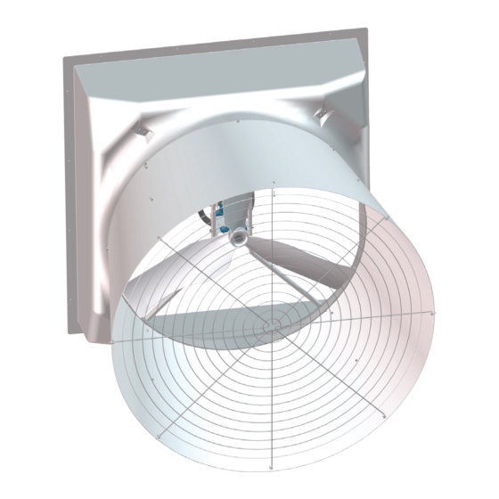
Page 30: Appendix 2 - Exploded Fan Overview
Appendix 2 - Exploded FAN Overview This drawing is the same for all models except for Direct Drives. The Direct Drive fans would not include the Belt Drive assembly parts. Follow the parts list for specific model part numbers. Not all model part numbers are included in the exploded view below. Part assemblies with hardware are detailed on the previous installation pages 10-27. ©2017 Valco Companies, Inc. - Page 31 Appendix 3 - Exploded Interchangeable FAN COMPONENTS Appendix 3 - 54” Interchangeable FAN COMPONENTS Parts List PART # DESCRIPTION Interchangeable FAN Components (ALL 54” Fans) 936032 1/4” X 1/4” X 1-3/4” KEY UNDERSIZE - LOW CARBON 954001 54” GUARD SCREEN (MN PART #FP389) 954184 CONE SECTION, 54”...
-
Page 32: Appendix 4 - Exploded Interchangeable Drive Kit
AUTO TENSIONER, 3.0”DIA PULLEY 3.5” ARM, 3/8-16 UNC BORE ZV747 BELT, AX47 49.3 OD LENGHT 48.3 DATUM LENGHT A WIDTH COG BELT 54” STD CAP DRV KIT, 1.5HP, 1PH, 60HZ 954200, 954200-SC, 954201, 954201-SC, 954205, 954206, 954200-BW 980024 12.25”X1”BORE BROWNING PULLEY 980032 MTR,1.5HP, 230V, 60HZ, 1P 1725RPM,56,SF1.0, IN.B... - Page 33 Appendix 4 - 54” Interchangeable Drive Kit Parts Lists 54” DRIVE KIT, 1.5HP, 1PH, WO/HW 3.25/10.25, AX48, W/TENSIONER 954210, 954210-SC, 954211, 954211-SC, 954215, 954216, 954605-SC,954606-SC, 954210-BW 980015 10.25”DIA. X 1” BORE A-PULLEY (ZV7431) 980030 49.3 DATUM BLACK COG BELT (VENDOR# AX48 & RAYDOT# ZV768) 980032 MTR,1.5HP, 230V, 60HZ, 1P 1725RPM,56,SF1.0, IN.B 980033...
-
Page 34: Appendix 5 - Exploded 54" Interchangeable Fan Housing
Z.P. Appendix 5 - 54” Interchangeable Fan Housing Parts Lists PART # DESCRIPTION 54” FAN HOUSING ASSY, 54” SHUTTER SS, INSIDE MOUNT, FIBERGLASS 954200-SC, 954210-SC, 954245-SC, 954280-SC, 954605-SC, 954615-SC, 954640-SC, 954685-SC, 954695-SC 420719 SPRKT CVR WARNING LABEL 936041 SHUTTER CAUTION LABEL (RAYDOT ZZ1895) 954163 FAN HOUSING, 54”SHUTTER INSIDE MOUNT, FIBERGLASS... - Page 35 BOLT,5/16-18X3/4”,FLG HD,S.S MH8097 BOLT,5/16-18x2.25,STD HD.,S/S MH8124 BLT,3/8-16X1 1/4,FLG HD,S,S 54” FAN HOUING GALV. INSIDE MOUNT ASSEMBLY 954200, 954205, 954210, 954215, 954240, 954245, 954280, 954285 010426 WASHER, FLAT 5/16” SAE ZP 010645 5/16” X 1” HEX BOLT 012789 5/16-18 NYLOCK NUT...
- Page 36 980020 1” BD DRIVE SHAFT - PLATED E NICKLE PLATING 980068 BRACKET, TENSIONER, GALV 54” FAN HOUSING ASSY, SHUTTER GALV, INSIDE MOUNT, FIBERGLASS 954200-BW, 954210-BW, 954245-BW, 954280-BW 420719 SPRKT CVR WARNING LABEL 501441 NUT, HEX FLANGE 5/16”-18, ZP JS500 690257...
-
Page 37: Appendix 6 - Fan Hardware Packagess
Z.P. S.S. S.S. PART # DESCRIPTION 954173 - HARDWARE BAG, F/54” SHUTTER GLV FRM FIBERGLASS FAN 953205, 954210, 954215, 954240, 954245, 954280, 954285, 954200-BW 012792 1/4-20 HEX FLANGE NUT 690362 SCREW, 1/4-20X1 SER FLG HD, ZP GR 5 690380 NUT, 1/4-20 PUSH, ZINC PLATED 690386 SCREW, 1/4-20 X 1”... - Page 38 Appendix 6 - Fan Hardware Packages PART # DESCRIPTION 954189 HARDWARE BAG, 54” OUTSIDE MNT SS FRM FIBERGLASS FAN 954201-SC, 954211-SC, 954246-SC, 954281-SC, 954606-SC, 954616-SC, 954641-SC, 954686-SC, 954696-SC 690343 SCREW, 1/4-20 X1 SER FLG HD SS 690380 NUT, 1/4-20 PUSH, ZINC PLATED 690386 SCREW, 1/4-20 X 1”...
-
Page 39: Appendix 7 - 54" Fan Blade Parts List
Appendix 7 - Fan Blade Parts List Used with HPM36W760MCAT, HPM36W760MGAT, HPM36W760MNAT DESCRIPTION 54” 50” 36” CAST ALUMINUM BLADE 1.75” BORE 954060 B718 FP489 GALVANIZED BLADE, 1” BORE 954031 936031 STAINLESS STEEL BLADE, 1” BORE 954032 B387 B758 ADAPTOR,SHAFT,1/2”to5/8” MH90431 ©2017 Valco Companies, Inc. -
Page 40: Appendix 8 - 50" Fan Parts Lists
Appendix 8 - 50” Fan Parts Lists PART # DESCRIPTION HPM50W340MCAT/ HPM50W340MNAT/ HPM50W340NCAT (340 models) 50” Interchangeable Parts 010421 3/16” FLAT WASHER 936032 1/4” X 1/4” X 1-3/4” KEY UNDERSIZE - LOW CARBON 936041 SHUTTER CAUTION LABEL (RAYDOT ZZ1895) 980015 10.25”DIA. - Page 41 Appendix 8 - 50” Fan Parts Lists PART # DESCRIPTION HPM50W340MSAT (340 model only) 010421 3/16” FLAT WASHER 950123 BODY ASSY 50” FBRGLSS FAN STAINLESS STEEL COMPONENTS 936041 SHUTTER CAUTION LABEL (RAYDOT ZZ1895) 980019 1” BORE PILLOW BLOCK BEARING ECC LOCKING COLLAR 980020 1”...
- Page 42 Appendix 8 - 50” Fan Parts Lists PART # DESCRIPTION HPM50W420LCAT/ HPM50W420LNAT (420 models) 50” Interchangeable Parts 936032 1/4” X 1/4” X 1-3/4” KEY UNDERSIZE - LOW CARBON 980015 10.25”DIA. X 1” BORE A-PULLEY (ZV7431) 980019 1” BORE PILLOW BLOCK BEARING ECC LOCKING COLLAR 980020 1”...
- Page 43 Appendix 8 - 50” Fan Parts Lists PART # DESCRIPTION HPM50W600MCAT/HPM50W600MNAT (600 models) 50” Interchangeable Parts 936032 1/4” X 1/4” X 1-3/4” KEY UNDERSIZE - LOW CARBON 980002 1HP MOTOR 1725RPM 3PH 50/60HZ 230/460V (RAYDOT M760) 980015 10.25”DIA. X 1” BORE A-PULLEY (ZV7431) 980019 1”...
- Page 44 Appendix 8 - 50” Fan Parts Lists PART # DESCRIPTION HPM50W610MCAT/HPM50W610MNAT (610 models) 50” Interchangeable Parts 936032 1/4” X 1/4” X 1-3/4” KEY UNDERSIZE - LOW CARBON 980002 1HP MOTOR 1725RPM 3PH 50/60HZ 230/460V (RAYDOT M760) 980007 3.5”DIAMETER PULLEY W/5/8”BORE (ZV742) 980019 1”...
- Page 45 Appendix 8 - 50” Fan Parts Lists PART # DESCRIPTION HPM50W650LCAT/HPM50W650LNAT (650 models) 50” Parts 010421 3/16” FLAT WASHER 936008 BELT DRIVE MOTOR MOUNT (FP430) 936032 1/4” X 1/4” X 1-3/4” KEY UNDERSIZE - LOW CARBON 948007 48” BOX FAN MOTOR MOUNT RAIL (FP428) 980007 3.5”DIAMETER PULLEY W/5/8”BORE (ZV742) 980015...
- Page 46 Appendix 8 - 50” Fan Parts Lists PART# DESCRIPTION 50” Interchangeable Parts HPM50W420LNAT-BW, HPM50W600MNAT-BW 950128 BODY ASSY, 50” BELT DRV, ZP,FG BLACK INT/WHITE EXT, SLTWL 501441 NUT, HEX FLANGE 5/16”-18, ZP JS500 (not shown) 690257 SCREW, 5/16-18 X 2-1/4 HHCS ZP 936008 BELT DRIVE MOTOR MOUNT (FP430) 936026...
- Page 47 Appendix 8 - 50” Fan Parts Lists PART # DESCRIPTION Parts Specific to model: HPM50W600MNAT-BW 950127 DRIVE KIT, 1.0HP, 3PH, W/ZPHW 3.25/10.25, AX48, W/TENSIONER 501441 NUT, HEX FLANGE 5/16”-18, ZP JS500 (not shown) 690389 SCREW, 5/16-18X3/4 SER FLG ZP 936026 3/8-16 X 1-1/4”...
-
Page 48: Appendix 9 - 36" Fan Parts Lists
Appendix 9 - 36” Fan Parts Lists PART # DESCRIPTION 936310 36” Fan 010421 3/16” FLAT WASHER 936094 BODY ASSY, 36” FBRGLSS FAN STAINLESS STEEL COMPONENTS 980019 1” BORE PILLOW BLOCK BEARING ECC LOCKING COLLAR 980020 1” BD DRIVE SHAFT - PLATED E NICKLE PLATING FP348W PMC 36”... - Page 49 Appendix 9 - 36” Fan Parts Lists PART # DESCRIPTION HPM36W340LNAT, HPM36W340LGAT, HPM36W600LNAT 36”Interchangeable Parts 936090 BODY ASSY 36” FBRGLSS FAN 936007 36” BOX FAN MOTOR MOUNT RAIL (FP522) 936008 BELT DRIVE MOTOR MOUNT (FP430) 980019 1” BORE PILLOW BLOCK BEARING ECC LOCKING COLLAR 980020 1”...
- Page 50 Appendix 9 - 36” Fan Parts Lists PART # DESCRIPTION HPM36W760MCAT, HPM36W760MGAT, HPM36W760MNAT 36” Interchangeable Parts 010421 3/16” FLAT WASHER 936032 1/4” X 1/4” X 1-3/4” KEY UNDERSIZE - LOW CARBON 980004 1/2HP MOTOR 1725RPM 1PH 230V 60HZ (RAYDOT M784) 980010 8.25”DIAMETER PULLEY W/1”...
- Page 51 Appendix 9 - 36” Fan Parts Lists Parts Specific to: HPM36W760MNAT 936007 36” BOX FAN MOTOR MOUNT RAIL (FP522) 936008 BELT DRIVE MOTOR MOUNT (FP430) 980012 BELT, BLACK COG 47.3 LG AX46 (FP456) FP489 BLADE, 36.188”1.75”ID, CT ALUM CAST ALUMINUM PART # DESCRIPTION HPM36W280MGA-BW, HPM36W760MNAT-BW 36”...
-
Page 52: Appendix 10 - Fiberglass And Polycones - 50" Fans
Appendix 10 - Fiberglass and Polycones - 50” Fans PART # DESCRIPTION PC50SB FP13235B 50” BLACK POLY CONE/SHORT FP408CH G SCREEN, 50”PMC SHORT CONE GUARD SCREEN PART # DESCRIPTION PC50SW FP13235A02W 50” WHITE POLY CONE/SHORT FP408CH G SCREEN, 50”PMC SHORT CONE GUARD SCREEN PART # DESCRIPTION FC50LW... -
Page 53: Appendix 12 - Customer Service
Appendix 12 - CUSTOMER SERVICE Dealer Name: _ _ _ _ _ _ _ _ _ _ _ _ _ _ _ _ _ PhoNe _ _ _ _ _ _ _ _ _ _ _ _ _ _ _ _ Street / PO Box __________________________________________________ Customer Service City __________________________________________________...
Need help?
Do you have a question about the 954200 and is the answer not in the manual?
Questions and answers