Chapters
Table of Contents

Subscribe to Our Youtube Channel
Related Manuals for rotork EH Pro Series


Summary of Contents for rotork EH Pro Series
- Page 1 EH Pro Range Installation and Maintenance Instructions This manual contains important safety information. Please ensure it is thoroughly read and understood before installing, operating or maintaining the equipment. PUB021-034-00 Date of issue 05/12...
- Page 2 Please read this publication before proceeding. When Rotork personnel or nominated agents are contracted to carry out site commissioning and/or acceptance, documentation of commissioned actuator Rotork Setting Tool Pro configuration can be made available for customer records.
- Page 3 This manual provides instruction on: THE ROTORK FLUID SYSTEMS EH Pro RANGE – A RELIABLE SOLUTION FOR ELECTRIC FAILSAFE AND MODULATING VALVE • Electrical (local and remote) and optional manual operation. CONTROL THAT YOU CAN COMMISSION AND INTERROGATE WITHOUT REMOVING ELECTRICAL COVERS. • Preparation and installation of the actuator onto the valve. Using the supplied infrared / Bluetooth setting sool to access the actuator • Subsequent commissioning and adjustment of the Basic Settings...
- Page 4 All electronics are protected in a watertight or explosion-proof enclosure. Other features include local manual control, indication feedback via dry contacts and 4-20 mA signal; or optional digital control via Modbus, Foundation Fieldbus, Profibus, DeviceNet or Rotork Pakscan communication systems. The EH Range can be supplied for operation with virtually any single phase, three phase, or 24 VDC power supply.
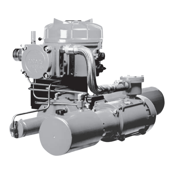
- Page 5 Identifying Actuator Parts Local/Remote 1/2" NPT Switch Cable Entries Open/Close Switch 1/2" NPT Cable Entries Display Window Manifold Local/Remote Switch Filler/Breather Accumulator Open/Close Manual Override Lever (If applicable) Switch Speed Control Valves Manual Override Pump Control Module Hydraulic Reservoir Oil Drain Terminal Compartment Plug Pump Actuator Center Body Motor...
-
Page 6: Table Of Contents
9.6 Analogue Control 1 9.7 Analogue Control 2 7 Commissioning 2 Storage Interrupter Timer 7.1 Setting Procedure Service 3 Operating your EH Pro Actuator 7.2 Rotork Setting Tool (old version) 9.10 Bus System Option – Pakscan 3.1 Electrical Operation 7.3 Rotork Setting Tool Pro 9.11 Bus System Option – Modbus [OP] Display – Local Indication ® 7.4 Rotork Bluetooth Setting Tool Pro 9.12 Bus System Option – Profibus DP [OP] 54... -
Page 7: Health And Safety
1 and Zone 2 classified hazardous area of the Rotork EH range of actuators be attention. locations only. It should not be installed required, it will be provided on request. - Page 8 Note: the PRODUCT SAFETY DATA WARNING: Compressed Springs SHEETS covering the type of All springs within the EH range of hydraulic oil supplied by Rotork actuators are pre-compressed. Springs Fluid Systems for use within the must not be removed from the actuator.
-
Page 9: Storage
Rotork Fluid Systems will not accept to a reduction in the safe use of, or the cables. EH enclosure:... -
Page 10: Operating Your Eh Pro Actuator
Operating your EH Actuator 3.1 Electrical Operation 3.2 Display–Local Indication 6. IR Icon – This icon flashes during Local Control infrared communication activity. Check that the power supply voltage agrees with that on the actuator With the selector positioned at Local 7. -
Page 11: Display Status Indication - Travel
Operating your EH Actuator continued Open Closed 3.3 Display Status Indication Timer Active • Interrupter Timer option – Travel The Red LED will be lit, the open symbol The Green LED will be lit, closed symbol enabled only. Interrupter Timer has and "Open Limit"... -
Page 12: Display Alarm Indication
• STALL IN MID POS - No movement in the configuration (set up) of the in the form of text and alarm icons. • OPTION CH 1 FAULT - Contact Rotork. detected between electrical limits after a actuator. Check and reset basic setting signal to move. -
Page 13: Esd Signal
Operating your EH Actuator continued ESD Signal Limit Switches 3.8.2 Closed Swtch Adjustment Speed Control A dedicated ESD digital input is When fitted, open and close limit Move the valve/actuator to the fully Speed control is a standard feature only provided with all standard actuators. -
Page 14: Optional Manual Operation
Operating your EH Actuator Optional Manual Operation continued 3.9.2 Spring-Return Adjustment 3.9.4 Double-Acting Adjustment Optional manual operation may have WARNING: (Accumulator Fitted) (Accumulator Fitted) been specified for your EH actuator. See specific manual override label For all EH actuators, optional manual as supplied with actuator, for Speed Control of the spring stroke Speed control of double-acting units... -
Page 15: Mounting The Actuator
Mounting the Actuator 5.1 Lifting 5.4 Mechanical Travel WARNING: WARNING: Do not lift the Adjustment If the actuator is fitted with an WARNING: actuator and valve combination via the actuator. Always lift the valve/ accumulator it must be drained to Refer to weights and measures When the actuator has been bolted the reservoir before adding oil. -
Page 16: Cable Connections
Cable Connections 6.1 Earth/Ground Connections A plastic bag with the actuator contains WARNING: the following: Ensure all power supplies are An M8 X 1.0 earth stud is located • Terminal screws and washers. isolated before removing actuator adjacent to the conduit entries for covers. -
Page 17: Connecting To Terminals
Cable Connections continued 6.4 Connecting to Terminals WARNING: Ensure the oil fill Heading On EExde enclosure units plug is always tight before stroking the actuator in either direction. connections to the power and control terminals must be made using AMP type 160292 ring tabs for power and earth terminals and AMP ATTENTION: RED PLASTIC PLUGS IN CONDUIT ENTRIES ARE FOR TRANSIT ONLY. -
Page 18: Commissioning
Commissioning 7.1 The Setting Procedure Configuration Settings Actuator Display The Rotork Fluid Systems EH actuators Settings covering the control, are designed so that commissioning indication and optional Position Display This may be an open or closed symbol may be carried out without removing equipment functions. -
Page 19: Rotork Setting Tool (Old Version
Commissioning continued 7.2 Rotork Setting Tool (old version) Specification Enclosure IP67 Certification EEx ia IIC T4 (intrinsically safe) FM, INT SAFE, Class I & II Div 1 Groups A B C D E F G, T4A CSA, Exia, Class I, II Div 1 Groups A B C D... -
Page 20: Rotork Setting Tool Pro
Display previous function across left. Decrease/change displayed function’s value or option setting. Increase/change displayed function’s value or option setting. Non-functional on EH actuators. Fig. 7.3. Rotork Setting Tool Pro Enter displayed value or option setting. Infrared transmitter window. Specification Non-functional on EH actuators. -
Page 21: Rotork Bluetooth ® Setting Tool Pro
Decrease/change displayed function’s value or option setting. Increase/change displayed function’s value or option setting. Initiate download/upload via Bluetooth. Enter displayed value or option setting. Infrared transmitter window. ® Fig. 7.4. Rotork Bluetooth Setting Tool Pro Specification Non-functional on EH actuators. Enclosure: IP54 Non-functional on EH actuators. - Page 22 Silicon Rubber keys are used to access and navigate Duracell, Procell, type MN1500 Note that a setting option or value is If the Rotork Setting Tool Pro and Rotork through the actuator set-up procedure GP, Super Alkaline, type GP15A highlighted.
-
Page 23: Setting Mode – Password
Commissioning continued 7.5 Entering the Actuator 7.6 Setting Mode – Password 7.7 New Password [PC] 7.8 Checking Mode To enable setting and adjustment of the To configure a new password, the The actuator function settings can be Setting Procedure actuator functions the correct password actuator must be in setting mode with the checked without entering the correct With the actuator securely mounted... - Page 24 7.10 Partial Stroke Test Refer to PUB095-001-00 for full This brings up an option to either Configuration instructions on the use of the Rotork cancel or confirm that the partial stroke This function performs a partial stroke EH Pro actuators include a Bluetooth Bluetooth ®...
-
Page 25: Checking Mode
Commissioning continued 7.11 Full Stroke Test 7.12 Crossroad [Cr] 7.13 The Actuator Display – This brings up an option to either cancel or confirm that the full stroke Setting/Checking Mode This function performs a full stroke test based on a setup test being completed test should be completed. -
Page 26: Returning To Valve Position Display
Commissioning continued 7.14 Returning to Valve In setting mode the Setting Tool keys will cause the setting to be Position Display changed. In checking mode the settings There are five ways of returning to valve cannot be altered. position display: In setting mode, once displayed, a new Approximately 5 minutes after the setting can be entered into the actuator... -
Page 27: Commissioning – Basic Functions
Commissioning – Basic Functions ELECTRICAL OPERATION MUST Settings and operation must NOT TAKE PLACE UNTIL THE BASIC be verified by electric operation SETTINGS HAVE BEEN MADE AND and function test of the actuator CHECKED. to ensure correct operation. The actuator’s Basic Settings affect the correct operation of the valve by the actuator. -
Page 28: Configuration Settings
Commissioning – Basic Functions continued Viewing the Basic Settings Function Description REFER TO SECTION 7, Position Display (This may be an open or closed symbol or % open value) COMMISSIONING Position and Internal Hydraulic Pressure Display Torque Password Password Change Bluetooth Partial Stroke Test Full Stroke Test... -
Page 29: C2 K C3
Commissioning – Basic Functions Close Action continued Each actuator is built in the factory to The actuator can be configured to Refer to valve manufacturer for be either Normally Closed, Normally either close on Pressure (hydraulic or recommended setting. Open or Stay-put depending on what spring) for seating valves or Limit for configuration was ordered. -
Page 30: Open Action
Open Action Close Pressure at Limit The actuator can be configured to This setting allows the maximum cut-off Refer to valve manufacturer for either open on Pressure (hydraulic or pressure in a normally open actuator recommended setting. spring) for back seating valves or Limit while travelling from the closed electrical for non-back seating valves. -
Page 31: Close Pressure (Mid)
Close Pressure at Mid Open Pressure at Limit This setting allows the maximum This setting allows the maximum cut-off cut-off pressure in a normally open pressure in a normally closed actuator actuator while travelling in mid-travel while travelling from the open electrical between the open and closed electrical limit to the open mechanical end stop Close Pressure... -
Page 32: Open Pressure (Mid)
Open Pressure at Mid Setting the Closed / Open Limit This setting allows the maximum To set the closed and open electrical cut-off pressure in a normally closed limits correctly, the actuator should actuator while in mid-travel between be moved to both the closed and the closed and open electrical limits open mechanical limits and the Open Pressure... -
Page 33: Set Close Limit
Set Closed Limit Set Open Limit Move the actuator to the closed Move the actuator to the open position position by using the local controls. by using the local controls. Set Close Limit Set Open Limit Move to Close Move to Open To change the function press the To change the function press the key until the required setting is... -
Page 34: General Settings
Menu Structure Pressure Display Partial Password Change Password Bluetooth Comms Stroke Test Full Stroke Test Contact r1 Crossroad Relay 1 Function Relay 1 Value Relay 1 Form General Close Close Open Open Closed Settings Pressure (at Limit) Pressure (at Mid) Pressure (at Limit) Pressure (at Mid) Remote Select Local Controls Low Power Mode LED Colour Change Language Full Stroke Setup... - Page 35 Accessing the Configuration Settings Configuration Settings CONFIGURATION SETTINGS Having established that the Basic In order to display the Configuration Settings have been correctly set, the Settings it is necessary to press the page Configuration Settings can now be key until [Cr] appears. configured to suit the site control and If you have chosen to enter Accessing Configuration Settings...
-
Page 36: Indication Contact R1
Indication Contact r1 Relay 1 Function Relay 1 Value [HA] Manual override switch Indication contact r1 may be set to trip To change the function press the This screen will only be displayed if the for any one of the following functions: key until the required setting is [Po] relay function is set to... -
Page 37: General Settings
Relay 1 Form General Settings Remote Select This section includes selecting the The correct setting for remote control [OF] : Select this option to disable [Po] If function Position % Open, remote control source for the actuator source will be determined by the type control from a remote source. - Page 38 Closed LED Local Control Low Power Mode Colour There are two options available to It is possible to use an external power To change the configuration press the There are two options available: configure the operation of the local supply such as a solar power system key until the required setting is Green (Default): [gr]...
-
Page 39: Digital Control
Language Full Stroke Setup (Reference Test) Digital Control The default display text language is This function performs a full cycle of the This brings up an option to either This section includes selecting the English. Consult the factory for which actuator and records the position and cancel or confirm that the reference action for 2-wire priority and settings... - Page 40 2-Wire Remote Over Pressure Hold Position Position Hysteresis Priority Hysteresis The default setting for 2-wire remote The default setting is to maintain the This feature works in conjunction This feature will vent the internal [SP] Stay Put. [HP] Hold Position priority is If open and current position (across the full stroke),...
-
Page 41: Esd / Partial Stroke Settings
Under Pressure ESD / Partial ESD Action (Software) Hysteresis Stroke Settings This feature will increase the internal The EH actuators have two separate An active ESD signal applied to the To change the ESD action press the hydraulic pressure in the actuator if it ESD circuits, a software driven circuit actuator will override any existing or key until the required setting is... - Page 42 ESD Override ESD Contact Type ESD Manual Reset Local Stop [On] ESD/Mains Loss: The feature allows you to choose if an This setting determines if a signal This feature allows the actuator to be Select this option active ESD signal should override Local should be applied, or removed to disabled from operational commands if the actuator must be manually reset...
- Page 43 Partial Stroke Temporary Loss of ESD Signal Position This feature determines what action These settings will work in conjunction This sets the position that the actuator [rE] should be taken if the ESD signal is lost with the ESD Manual Reset option.
- Page 44 Partial Stroke Setup (Reference Test) This function performs a partial This brings up an option to either stroke of the actuator and records cancel or confirm that the reference the position and internal hydraulic partial stroke test should be completed. pressure against time in both the open [No] To cancel the test: Ensure that...
-
Page 45: Analogue Control 1
Demand Input Demand Input Analogue Control 1 Analogue Input Type Calibration (Closed Limit) Calibration (Open Limit) This section describes how to select the The analogue input signal can either Apply the analogue Close demand Apply the analogue Open demand correct analogue signal type (current or be set as current (0-20 mA) or voltage current or voltage signal corresponding current or voltage signal corresponding... - Page 46 Set CPT Output CPT – Set Closed CPT – Set Open The CPT output can be set to either To calibrate the CPT output for the To calibrate the CPT output for the represent the position or internal closed limit position, connect a current open limit position, connect a current hydraulic pressure as a current (4 - 20 measuring device to the CPT terminals.
-
Page 47: Analogue Control
Analogue Signal Analogue Control 2 Failure Action This sets the action to be taken upon Selectable Deadband and Hysteresis Some understanding of the operational Momentum/Solenoid response times loss of the analogue signal. The set values (independent in both directions design parameters is required to within the system may cause the action will be taken once the demand to optimise for different operating... - Page 48 Analogue Input – Analogue Input – Hysteresis Hysteresis Closing Close Deadband Open Deadband Opening The closing Deadband value is displayed The opening Deadband value is The closing hysteresis value is displayed The opening hysteresis value is as a % of full stroke. The default value displayed as a % of full stroke.
-
Page 49: Interrupter Timer
Position in Valve Option Interrupter Timer Interrupter Timer Closing Stroke for Interrupter Timer Enabled/Disabled Direction Timer to Start The interrupter timer enables pulsed To enable the Interrupter Timer press The default for timer direction is [CL], Using the key select the position the + or - keys to toggle between [OF] timer operation will start in closing “stop/start”... - Page 50 Position in Valve Opening Interrupter Timer Interrupter Timer Interrupter Timer Interval Stroke for Timer to Stop On Time Off Time Using the key select the position This function changes the units of Using the key select the Using the key select the for the TIMER TO STOP WHEN THE time applied to [Jn] and [JF] between actuator run period in the range 100...
- Page 51 ESD Override Example Interrupter Timer The interrupter timer may be overridden An actuator fitted with the interrupter when the actuator is under software timer and set as the example shown in ESD signal command. This will mean these instructions would operate at: the actuator will run to limit without Rated speed from full Open to “stop/start”...
-
Page 52: Service
A full Yes (move away STALL AT LIMIT functional test should be carried out to first) ensure any underlying fault does not PS ERROR affect the actuator performance. If the DEMAND FAULT fault persists then contact Rotork. PS UNABLE TO RUN OPTION CH 1 FAULT OPTION CH 2 FAULT EEPROM MISSING... - Page 53 Test Lights Test Lights Test Lights Option 2 Firmware Version Option 1 Version Function Function Function Version This option illuminates all the segments, This option displays the current This option displays the current This option displays the current dots and icons on the display along firmware version number that is firmware version number that is firmware version number that is...
-
Page 54: Bus System Option - Pakscan
9.10 Bus System Pakscan Node Pakscan Option Pakscan Address Baud Rate Setting instructions for actuators The actuator Pakscan Field Control Unit The actuator Pakscan Field Control Unit including an optional Pakscan Field must be allocated a unique loop node baud rate must be set to the loop baud Control Unit –... - Page 55 Pakscan Remote Auxiliary Input Mask The EH actuator has the facility to accept 4 auxiliary inputs (AUX1–AUX4). These Rules are used when supplementary remote control or digital auxiliary inputs are required 1. Function bit set to ‘‘0’’ in addition to the standard control and feedback features incorporated into the Pakscan card.
- Page 56 Pakscan Remote Pakscan Remote Auxiliary Input (continued) Auxiliary Input 5. Remote I/P Setting Using the keys display the Control Type Ensure that the correct [Od] setting is selected (refer to section 9.3). required mask setting. Network For Pakscan this is [oP] Aux I/P Mask 0000 1111 The factory default for [PF]...
-
Page 57: Bus System Option Modbus [Op]
9.11 Bus System Modbus Node Modbus Baudrate Address Option Modbus [OP] Setting instructions for actuators The Modbus module must be allocated The Modbus module must be set to the including an optional Modbus RTU a unique address. RS485 highway baudrate. To set the module –... - Page 58 Modbus Remote Auxiliary Input The EH Pro actuator has the facility to accept 4 auxiliary inputs (AUX1 – AUX4). Rules These are used when supplementary remote control or digital auxiliary inputs are 1. Function bit set to ‘‘0’’ required in addition to the standard control and feedback features incorporated into the Modbus module.
- Page 59 Modbus Remote Modbus Parity Auxiliary Input (continued) 5. Remote I/P Setting Where Modbus parity bit detection is Using the keys display the Control Type Ensure that the correct [Od] setting is selected (refer to section 9.3). required mask setting. used the module must be set with the parity bit setting of the host.
-
Page 60: Bus System Option Profibus Dp [Op]
[Pb] has no relevance for the Refer to publication PUB088-004 Rotork Profibus DP Mk.2 card. available from www.rotork.com Therefore, if the Rotork Profibus DP Mk.2 The actuator power must be card is fitted, press the to display: cycled for the changes to take effect. - Page 61 Profibus Remote Auxiliary Input The EH Pro actuator has the facility to accept 4 auxiliary inputs (AUX1–AUX4). Rules These are used when supplementary remote control or digital auxiliary inputs are 1. Function bit set to ‘‘0’’ required in addition to the standard control and feedback features incorporated into the Profibus module.
- Page 62 Profibus Remote Profibus Remote Auxiliary Input (continued) Auxiliary Input 5. Remote Source Setting [Od] Using the keys display the Control Type Ensure that the correct [Od] setting is selected (refer to section 9.3). required mask setting. Network For Profibus this is [OP] Aux I/P Mask 0000 1111 The factory default for [PF]...
-
Page 63: Bus System Option Devicenet
9.13 Bus System DeviceNet Node DeviceNet Baudrate Option DeviceNet Address Setting instructions for actuators The DeviceNet module must be The DeviceNet module must be set to including an optional DeviceNet DFU allocated a unique address. the DeviceNet highway baudrate. module – check wiring diagram for Using the keys display the Using the... - Page 64 DeviceNet Remote Auxiliary Input Rules The EH Pro actuator has the facility to accept 4 auxiliary inputs (AUX1–AUX4). These are used when supplementary remote control or volt free digital auxiliary inputs are 1. Function bit set to ‘‘0’’ required in addition to the standard control and feedback features incorporated into the DeviceNet module.
- Page 65 DeviceNet Remote Auxiliary Input (continued) 5. Remote I/P Setting Using the keys display the Ensure that the correct [Od] Control Type setting is selected (refer to section 9.3). required mask setting. Network For DeviceNet this is [OP] The factory default for [PF] Aux I/P Mask is [OF] 0000 1111...
-
Page 66: Bus System Positioning Control Settings
[FH] High Set Point Position [Fd] Deadband the host on startup unless the GSD Press the key to display: files are locked on the Profibus card. Motion Inhibit Time [Ft] Refer to publication PUB088-004-00 available from www.rotork.com... - Page 67 Modbus, Profibus & Modbus, Profibus Bus System DeviceNet & DeviceNet Motion Inhibit Time (MIT) Action on Loss of Signal Failsafe Action MIT sets the minimum time between Modbus, Profibus & DeviceNet modules Modbus, Profibus & DeviceNet failsafe action when [FA] is enabled. successive position commands being can be set to respond on loss of host actioned.
- Page 68 Reset to Default Configuration Settings All EH actuator functions are configured to a set of Rotork Fluid Systems default (standard) settings before despatch, see the table opposite. When requested, [r1] [CL] Relay 1 Function Closed Limit alternative settings specified with the order will be used. When site commissioning...
- Page 69 Reset to Default continued [FF] [OF] Analogue Signal Failure Action No Alarm [dC] [10] Closing Deadband Adjustment 1.0% [dO] [10] Opening Deadband Adjustment 1.0% Reset to Factory [HC] [05] Closing Hysteresis Adjustment 0.5% Confirm? [HO] [05] Opening Hysteresis Adjustment 0.5% [OJ] [OF] Interrupter Timer Enable...
-
Page 70: Maintenance, Monitoring And Troubleshooting
Troubleshooting Standard Applications: actuator for 30 minutes and check • Ensure valve stems and drive nuts are Every Rotork Fluid Systems actuator has 32 cSt Mineral Oil that the actuator has not drifted off clean and properly lubricated. been fully tested before despatch to give Mobil DTE 10 Excel 32 the open limit. -
Page 71: Environmental
Maintenance, Monitoring and Troubleshooting continued 10.2 Environmental End user advice on disposal at end of life of the product Subject Definition Remarks / examples Hazardous Recyclable EU Waste Code Disposal Electrical & Printed circuit boards All Products 20 01 35 Electronic Wire Use specialist recyclers... -
Page 72: Help Screens
Limit Flags Help Screens Moving Closed With the actuator powered up and For troubleshooting, access the Open Holding Limit Close Limit Local or Stop selected, nine Help following Help Screens and refer to text: Bar On = Actuator is moving in the Screens can be accessed using the Closed direction. - Page 73 Local Controls Remote Signals Local Fitted Remote 1: ESD Local Mode Hand Remote 1: Remote 2: Selected Operation Open Bar On = Local controls fitted. Bar On = ESD signal present. Hand Operation Remote 2: Open Local Local Remote 1: Remote 2: Bar On = Manual override in use.
- Page 74 Digital Feedback Control Flags Fault Relay Output P.Stroke / Remote- Int Timer Local Command Started Bar On = Fault relay energised. Note: Bar indication is real time and Over Int. Timer Fault Relay Pressure Inhibiting Output reactive. Hydraulic Monitor Status Relay Output Solenoid Driver...
- Page 75 Driver Outputs Error Flags 1 Note: Bar indication is real time and Solenoid Pressure No. 1 Transducer Fault reactive. Position Solenoid Closing EEPROM Transducer No. 2 Checksum Fault Solenoid Opening Hardware Solenoid No. 3 Fault Driver Fault Pump Local Controls Hydraulic Fault Power Fault...
- Page 76 Error Flags 2 Driver Logic Actuator Stalled Inhibit Command Open No Expected Loss of Analogue Command Movement Bar On = Actuator movement is stalled Bar On = Actuator is operating using Demand Signal [St]. the interrupter timer. Over Partial Close De-energise Partial Stroke Fault De-energise All Command...
-
Page 77: Weights And Measures
12.1 Binary, Hexadecimal and Weights and Measures Decimal Conversion Table Consult job specific EH transmittal package that was supplied with actuator. See table below: BINARY HEX DEC BINARY HEX DEC BINARY HEX DEC BINARY HEX DEC BINARY HEX DEC BINARY HEX DEC BINARY HEX DEC... -
Page 78: Actuator Nameplate
Actuator Nameplate The actuator nameplate is engraved with the following information: Application Type Serial Number: Have this available if contacting Rotork Fluid Systems Factory for assistance. Attribute/Category Watertight Mutual ATEX IECEx (FM) Actuator Type: EH-Range actuator production version (i.e. EH 1.1 Pro). -
Page 79: Hazardous Area Approvals
The table below shows fuse FM. Class II, Division 2, Gas Group E, F & to www.rotork.com for the latest specification reference. G (DIP/II/1/EFG) information. Enclosure: NEMA Type 6 Rotork can supply actuators to national Temperature Code: T4 standards not listed below. For details Temperature: -40°C to +60°C Input Power Voltages Bussman Order Code please contact Rotork. *Option: -50°C to +60°C... -
Page 80: Special Conditions Of Safe Use
Special Conditions of Safe Use (Explosion-proof Actuators) In accordance with clause 5.1 of EN 60079-1, the critical dimensions of flamepaths relevant to the EH1.1 are as follows: Flamepath Maximum Gap (mm) Minimum L (mm) Manifold Block/ Main Enclosure 0.10 12.50 (Flange Joint) Control Knob Shaft/ Main Enclosure 0.20... -
Page 81: Appendix A
2.4 Attach the Swivel Connector (5) 2.10 Re-install valve cap. assembly by screwing the gas chuck for purchase from Rotork Fluid Systems. to the charging assembly gas valve (4) to the valve stem of the accumulator. Request Rotork part number 90-183 and tighten to 1-2 Nm / 10-15 in lbs. - Page 82 Appendix A – Accumulator Pre-charge & Removal continued Accumulator Removal 4.1 Attach the charging assembly and follow steps 3.2 through 3.5. 4.2 Open bleed valve (3) until all gas pre-charge is released from the accumulator. 4.3 Remove the charging assembly. The accumulator can now be safely removed from the system.
- Page 83 Rotork Sales and Service If your Rotork Fluid Systems actuator has been correctly installed and sealed, it will give years of trouble-free service. Should you require technical assistance or spares, Rotork guarantees the best service in the world. Contact your local...
- Page 84 TEMPORAIRE. POUR UNE PROTECTION DEFINITIVE UTILISER DES BOUCHONS METALLIQUES. change without notice. The latest product and technical information is available at our website www.rotork.com The names Rotork and Rotork Fluid Systems are registered trademarks. Rotork recognises all registered trademarks. POWTG0612...
Need help?
Do you have a question about the EH Pro Series and is the answer not in the manual?
Questions and answers