Table of Contents

Related Manuals for rotork IQT


Summary of Contents for rotork IQT
- Page 1 IQT Range Installation and Maintenance Instructions This manual contains important safety information. Please ensure it is thoroughly read and understood before installing, operating or maintaining the equipment. PUB002-004-00 Date of issue 01/11...
- Page 2 The Rotork Setting Tool allows actuator control, indication and protection functions to be configured to suit site requirements. In addition, the new Setting Tool Pro also allows downloading of datalogger and uploading/downloading of configuration files. Files are transferred to and from the Setting Tool Pro via Rotork Insight.
- Page 3 The actuator containing the Setting Tool will be identified with a yellow label on the terminal cover. * Sales and Service. Visit our web site at www.rotork.com for more information on the IQT and other Rotork actuator ranges. Refer to Publication E185E for repair, overhaul and...
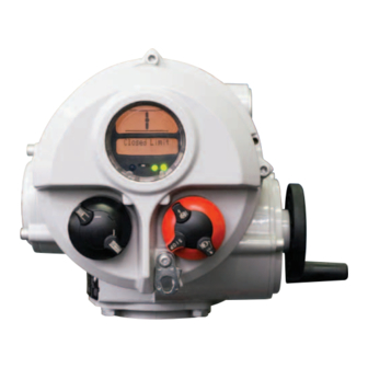
- Page 4 Identifying Actuator Parts Display window Conduit entries Battery sealing plug Metal (8mm Allen key required) Plastic (10mm Allen key required) as appropriate. Control Cover Hand / Auto lever IQelecCvr IQelecCvr Hand wheel Name plate Terminal Cover Local / Remote / Stop selector Motor cover Base...
-
Page 5: Table Of Contents
7.1 The Setting Procedure 3.5 Display Status Indication – Control 11.2 Help Screens 7.2 The Rotork Setting Tools 3.6 Display Alarm Indication 11.3 IQT Infrared Diagnostic & Configuration 78 7.3 Entering the Actuator 4 Preparing Drive Bush 11.4 Environmental Setting Procedure 4.1 Bases F05 to F07... -
Page 6: Health And Safety
Rotork IQT range of actuators be locations with an ignition temperature impact to the viewing window required, it will be provided on request. -
Page 7: Storage
Switch on power supply. It to become stuck in the seated/ to commission the IQT actuator. is not necessary to check phase rotation. backseated position. Rotork cannot accept responsibility for Fig. -
Page 8: Display-Local Indication
3.3 Display–Local Indication Open Closed description text in the lower display. The two tri-colour LED's will be Red, The two tri-colour LED's will be Green, 6. Battery Alarm Icon - This icon will be the open symbol and "Open Limit" will closed symbol and "Closed Limit"... -
Page 9: Display Status Indication - Travel
Remote control – Travel enabled only. Interrupter Timer has selected – red selector. The IQT display provides alarm indication stopped the actuator mid travel for a The IQT display provides real time in the form of text and alarm icons. - Page 10 THERMOSTAT TRIP Valve Alarms • Motor control – contact Rotork. should be replaced immediately. It thermostat has tripped due to TORQUE TRIP CL • tripped off on torque is essential that the correct battery EEPROM MISSING extended motor operation.
-
Page 11: Preparing Drive Bush
Fig. 4.1 Fig. 4.2 of operation are correct for valve The range of IQT drive bushes is shown operation. Secure the drive bush with 4.2 Bases F10 to F14 in figure 4.3. Please refer to PUB002- the capscrews. -
Page 12: Mounting The Actuator
50%. Commissioning of IQTM range as indicated in Figure 5. At all times actuators is identical to the standard trained and experienced personnel IQT (refer to Sections 7, 8 and 9). should ensure safe lifting, particularly Fig. 5.1 when mounting actuators. -
Page 13: Stop Bolts
Stop Bolt sizes. Secure actuator to valve with four The IQT stop bolts are located below fixing bolts. Check that the cast groove the terminal compartment. Stop bolt IQT 125 to 500: M12 bolt requiring in actuator base is not obstructed see adjustment allows +/–... -
Page 14: Cable Connections
Rotork publication No. E135E Electric replace screen. a self-adhesive yellow label on the Only appropriate certified Explosion- motor performance data for IQT range outside of the terminal compartment When all connections are made ensure Proof entry reducers, glands or conduit actuators. -
Page 15: Commissioning
Commissioning 7.1 The Setting Procedure Configuration Settings Actuator Display The Rotork IQT range of actuators is the Settings covering the control, first that enables commissioning to be indication and optional Position Display This may be an open or closed symbol carried out without removing covers. -
Page 16: The Rotork Setting Tools
Commissioning continued 7.2 The Setting Tool (old version) Specification Enclosure IP67 Certification EEx ia IIC T4 (intrinsically safe) FM, INT SAFE, Class I & II Div 1 Groups A B C D E F G, T4A CSA, Exia, Class I, II Div 1 Groups A B C D Power supply 9V Battery (supplied and fitted) Operating range... - Page 17 7.2 The Setting Tool Pro (new version) Specification Enclosure IP54 This Setting Tool Pro has been built in accordance with the following standards: USA - Hazardous Area. Factory Mutual - Explosion Proof to NEC Article 500. Intrinsically Safe, Class 1, Div 1, Groups A, B, C & D, T4. Canada - Hazardous Area.
- Page 18 This new feature has been introduced GP, Super Alkaline, type GP15A instruction to the actuator by infra-red with the new Rotork Setting Tool pulses and must therefore be directly in Pro. It allows the user to download Other types of AA size batteries,...
-
Page 19: Entering The Actuator
7.3 Entering the Actuator 7.4 Setting Mode – Password 7.5 New Password [PC] 7.6 Checking Mode To enable setting and adjustment of the To configure a new password, the The actuator function settings can be Setting Procedure actuator functions the correct password actuator must be in setting mode with checked without entering the correct With the actuator securely mounted... -
Page 20: Crossroad
Commissioning continued 7.7 Crossroad [Cr] 7.8 The Actuator Display – 7.9 Returning to In setting mode the Setting Tool Setting/Checking Mode keys will cause the setting to be Valve Position Display Actuator functions as laid out in the changed. In checking mode the settings There are five ways of returning to valve cannot be altered. -
Page 21: Commissioning - Basic Settings
Commissioning – Basic Settings ELECTRICAL OPERATION MUST Power Off Setting NOT TAKE PLACE UNTIL THE BASIC IQT allows settings to be viewed and SETTINGS HAVE BEEN MADE AND set without main power. To enable this CHECKED. function, engage handwheel drive and rotate until the output drive moves The actuator’s Basic Settings affect... -
Page 22: Basic Settings Contents
Viewing the Basic Settings Function Description REFER TO SECTION 7, COMMISSIONING Position Display (This may be an open or closed symbol or a % open value.) Torque and Position Display Torque Password Password Change IrDA Torque Reference Profile Configuration Crossroad Configuration Settings, refer to page 32. - Page 23 Direction to Close The actuator can be configured to be Using the key, display the Having ensured that the display clockwise or anti-clockwise to close. corresponds to the established character conforming to correct closing Manually operate actuator and valve direction. closing direction to establish correct closing direction.
- Page 24 Close Action NOTE: IQT actuators are designed to stop at Using the key, display the When set to close on torque, the end of travel by torque limitation required option. the actuator will apply the level of against the actuator stop bolts. Stop...
- Page 25 Open Action NOTE: IQT actuators are designed to stop at Using the key display the When set to open on torque, the end of travel by torque limitation required option. the actuator will apply the level of against the actuator stop bolts. Stop...
- Page 26 Close Torque The value of torque available in the Using the keys, the display close direction can be configured. recommended value. In the absence of a recommended torque value, try a low Refer to valve manufacturer setting and increase until satisfactory Close Torque for recommended value.
- Page 27 Open Torque NOTE: The value of torque available in the The opening torque value can be Rated torque is quoted on the open direction can be configured. varied between 40% and Rated, in 1% actuator nameplate. Boost torque is at increments.
- Page 28 Set Limit Closed Set Limit Open NOTE: With [LC] displayed With [LO] displayed It is possible to set the Open Limit Position [LO] first. Torque Set Open Limit Set Close Limit Move to Open Move to Close Torque Limit Open Limit Closed Move valve manually to the closed Move valve manually to the open...
- Page 29 IQT operating time can be adjusted between 25% and 100% of the maximum Positional Display time (50% and 100% for IQT2000). IQT are factory set at the maximum speed. IQTM actuators are dispatched with the minimum speed set. To access speed...
- Page 30 Return to Positional Display If the procedure has been followed as described, the positional display will indicate that the actuator is in the open position. Torque Select Remote control momentarily, using the red selector to exit setting procedure and then select required control: Local, Stop or Remote.
-
Page 31: Commissioning - Configuration Settings
Configuration Functions Power Off Setting The Configuration Settings can be configured to suit site control and IQT allows settings to be viewed and indication requirements. It is important set without mains power. To enable that Basic Settings such as limits and... - Page 32 Inhibit LED Colour Language Option Selection Option Functions – If Analogue, Bus System or Interrupter Timer control options are fitted their appropriate set-up screens will be automatically inserted here. IQT Speed IQT Type Setting Setting Software Option 1 Option 2...
-
Page 33: Configuration Settings Contents
9.14 Setting Tool Local Control PRESS THE 9.15 Inhibit Operation After Power Loss 9.16 Indicator LEDs 9.17 Display Language 9.18 Default Options 9.19 Actuator Type Setting 10.3 IQT Battery Failsafe Commissioning Instructions 11.2 Help Screens 11.3 IrDA Diagnostics and Configuration... - Page 34 Indication Contacts Heading Contact S1 - Function S1, S2, S3 and S4 Indication contacts S1 [r1], S2 [r2], S3 Using the key display the desired Open Interlock Active [Ol] [r3] and S4 [r4] may each be set to trip function. Close Interlock Active [Cl] for any one of the following functions:...
- Page 35 Contact S1 Contact S1 - Value Contact Form This screen will only display if relay Use the keys to select between Position Open Normally Open Normally function is set to [P0] and [ Closed When the S contact function is set to [P0], the required intermediate position PRESS THE KEY.
- Page 36 ESD as a factory set, bypass function. Unless specified with and A5. removed to activate the command. hard-wired option only. Contact Rotork order, the control mode configuration The default action under an active ESD Press the key to choose the for information.
- Page 37 ESD Override ESD Override Maintain 2-wire Remote Interlocks Local Stop Local Control Priority The default setting for ESD Override The default setting for ESD Override The default setting for Local Actuator The default setting for 2-wire Remote Stay Put Interlocks is [OF] .
- Page 38 Interlocks Partial Stroke Conditional Control Torque Switch Bypass Actuators are delivered with the The actuator can be set to carry out a Where a high level of safety integrity The default setting for Torque Switch Disabled interlock facility disabled [OF] partial stroke test using a signal applied is required, Conditional Control can Bypass is [OF]...
- Page 39 Option Extra Display Extra Contact Indication Contacts Set-up Screens Extra indication contacts S5 [r5], S6 The action of turning on the Extra [r6], S7 [r7] and S8 [r8] are available as Contact Option makes an additional an option. series of set-up screens available Check actuator circuit diagram for inclusion.
- Page 40 Option CPT [OI] – 4-20mA Indicator Setting instructions for actuators NOTE: If the actuator has options Folomatic and CPT, redefining the including a CPT providing 4-20mA CPT, will require the Folomatic to be analogue position feedback. recommissioned (refer to Section 9.6 Folomatic [OI] page 37).
- Page 41 Option Folomatic – Analogue Folomatic Feedback Analogue Control Signal Type Setting instructions for This instruction lists the Folomatic Before commissioning of the Folomatic Current key select [ l] Using the function displays in their sequence and functions can begin, the Folomatic actuators including a Folomatic Voltage for current input signal or [ U]...
- Page 42 Input Valve Position Valve Position Deadband Signal Range LOW Set Point HIGH Set Point Adjustment Using the key select for required If the actuator hunts or responds APPLY MINIMUM APPLY MAXIMUM unnecessarily to a fluctuating input signal within the range of 0–5mA or SET POINT SIGNAL SET POINT SIGNAL volts, 0–10mA or volts or 0–20mA or...
- Page 43 Motion Inhibit Action On Loss of Manual/Auto Failsafe Action Timer Adjustment Set Point Signal Selection The motion inhibit timer introduces Using a switched input you can select Loss of Signal Failsafe action when [FA] key to enable [O ] or a delay in the actuator response to between Folomatic (Auto) operation and Failsafe...
- Page 44 Remote Control Source Remote Control Source The available forms of remote control The setting of Remote Control Source To change the remote source press the are listed below: will be determined by the option that key until the required setting is has been fitted, if any.
- Page 45 Bus System Pakscan Node Pakscan Option Pakscan Address Baud Rate Setting instructions for actuators The actuator Pakscan Field Control Unit The actuator Pakscan Field Control Unit including an optional Pakscan Field must be allocated a unique loop node baud rate must be set to the loop baud Control Unit –...
- Page 46 Pakscan Remote Auxiliary Input Mask Rules The IQT actuator has the facility to accept 4 auxiliary inputs (AUX1–AUX4). These are used when supplementary remote control or digital auxiliary inputs are required 1. Function bit set to ‘‘0’’ in addition to the standard control and feedback features incorporated into the Pakscan card.
- Page 47 Pakscan Remote Pakscan Remote Heading Auxiliary Input (continued) Auxiliary Input 5. Remote I/P Setting Using the keys display the Control Type Ensure that the correct [Od] setting is selected (refer to page 40). required mask setting. Network For Pakscan this is [oP] Aux I/P Mask 0000 1111 The factory default for [PF]...
- Page 48 Bus System Modbus Node Modbus Baudrate Address Option Modbus [OP] Setting instructions for actuators The Modbus module must be allocated The Modbus module must be set to the including an optional Modbus RTU a unique address. RS485 highway baudrate. To set the module –...
- Page 49 Modbus Remote Auxiliary Input Rules The IQT actuator has the facility to accept 4 auxiliary inputs (AUX1 – AUX4). These are used when supplementary remote control or digital auxiliary inputs are required 1. Function bit set to ‘‘0’’ in addition to the standard control and feedback features incorporated into the Modbus module.
- Page 50 Modbus Remote Heading Modbus Parity Auxiliary Input (continued) 5. Remote I/P Setting Using the keys display the Where Modbus parity bit detection is Control Type Ensure that the correct [Od] used the module must be set with the setting is selected (refer to page 40). required mask setting.
- Page 51 7E (for value above 7E). files are locked on the Profibus card. Rotork Profibus DP Mk.2 card. Refer to publication S420E available Therefore, if the Rotork Profibus DP Mk.2 from www.rotork.com card is fitted, press the to display: Aux I/P Mask...
- Page 52 Profibus Remote Auxiliary Input Rules The IQT actuator has the facility to accept 4 auxiliary inputs (AUX1–AUX4). These are used when supplementary remote control or digital auxiliary inputs are required 1. Function bit set to ‘‘0’’ in addition to the standard control and feedback features incorporated into the Profibus module.
- Page 53 Profibus Remote Profibus Remote Heading Auxiliary Input (continued) Auxiliary Input 5. Remote Source Setting [Od] Using the keys display the Control Type Ensure that the correct [Od] setting is selected (refer to page 40). required mask setting. Network For Profibus this is [OP] Aux I/P Mask 0000 1111 The factory default for [PF]...
- Page 54 9.11 DeviceNet Node Option DeviceNet DeviceNet Baudrate Address Setting instructions for actuators The DeviceNet module must be The DeviceNet module must be set to including an optional DeviceNet DFU allocated a unique address. the DeviceNet highway baudrate. module – check wiring diagram for Using the keys display the Using the...
- Page 55 DeviceNet Remote Auxiliary Input The IQT actuator has the facility to accept 4 auxiliary inputs (AUX1–AUX4). These Rules are used when supplementary remote control or volt free digital auxiliary inputs are 1. Function bit set to ‘‘0’’ required in addition to the standard control and feedback features incorporated into the DeviceNet module.
- Page 56 DeviceNet Remote Heading Auxiliary Input (continued) 5. Remote I/P Setting Using the keys display the Control Type required mask setting. Ensure that the correct [Od] setting is selected (refer to page 40). Network For DeviceNet this is [OP] Aux I/P Mask 0000 1111 The factory default for [PF] is [OF]...
- Page 57 High Set Point Position Deadband [FH] [Fd] the actuator may be overwritten by Press the key to display: the host on startup unless the GSD Motion Inhibit Time [Ft] files are locked on the Profibus card. Refer to publication S420E available from www.rotork.com...
- Page 58 Modbus, Profibus & Modbus, Profibus Bus System DeviceNet & DeviceNet Motion Inhibit Time (MIT) Action on Loss of Signal Failsafe Action MIT sets the minimum time between Modbus, Profibus & DeviceNet modules Modbus, Profibus & DeviceNet failsafe successive position commands being can be set to respond on loss of host action when [FA] is enabled.
- Page 59 Position in Valve 9.13 Option Interrupter Timer Interrupter Timer Closing Stroke for Interrupter Timer Enabled/Disabled Direction Timer to Start Setting instructions for actuator When fitted, the timer will be The default for timer direction is [CL], Using the key select the position timer operation will start in closing for the TIMER TO START WHEN THE including an interrupter timer.
- Page 60 Position in Valve Opening ESD Override Contactor On Time Contactor Off Time Stroke for Timer to Stop Interrupter Timer Using the key select the position Using the key select the actuator Using the key select the actuator The interrupter timer may be overridden for the TIMER TO STOP WHEN THE when the actuator is under ESD signal run period in the range 1–99 seconds.
- Page 61 Local Only which may cause control or process The displayed option will flash (stored) Control Disabled [OF] problems. indicating that it has been set. Remote Only For “ON” and “OFF” times in excess of 99 seconds apply to Rotork.
- Page 62 9.17 Indicator LEDs Close LED Colour Mid-Travel LED Display Language The colour of the LEDs on the IQT The default close limit position indicator The default for mid travel position colour is [ g Green display are user configurable. These...
- Page 63 9.18 Default Options [d1] and [d2] All IQT functions are configured to a set of Rotork default (standard) settings before Rotork standard [d1] Default settings for IQT: despatch, see the table opposite. When requested, alternative settings specified Function [d1] Default Setting with the order will be used.
-
Page 64: Default Options
9.18 Default Options [d1] and [d2] cont. Rotork standard [d1] Default settings continued: The Rotork standard default settings are subject to change without notice. If specified with order, [d1] settings will be configured as requested. Function [d1] Default Setting To reinstate [d1] settings, with [d1] displayed. - Page 65 Motor Speed Control PCB be replaced with a spare, the actuator type must be set. Failure to set the correct type will invalidate the actuator performance specification and warranty. To set the actuator types go to setting [Ab] in the secondary IrDA IQT Type comms functions. IQT 125...
-
Page 66: Iqt Battery Failsafe Instructions
Folomatic proportional control or serial TERMINALS 14 (+) AND 21 digital network signals are not available. (–). DC BATTERY POWER MAY BE *On loss of AC supply the IQT battery SUPPLIED TO THESE TERMINALS failsafe does not support customer WHEN THE AC ELECTRICAL... -
Page 67: Specification
The batteries are however once the IQT is connected to sealed lead acid type and require no AC power the batteries will automatically maintenance. Refer to section 11, page begin charging to bring them to the 67 for IQT range maintenance. -
Page 68: Commissioning Instructions
If ESD and/or interlocks do not form Ensure the two 20A fuses located in a as detailed in table the below: Commissioning Instructions in part of the IQT control scheme then no plastic bag are kept safely - DO NOT FIT this manual. wiring is necessary. - Page 69 Tighten the 4 fixing bolts using a 6mm allen key. Set up of the battery pack is now complete. To enable failsafe operation, settings within the IQT actuator must now be made. Fig. 4 Fig. 6...
- Page 70 To test the failsafe function, switch off automatically perform an ESD using [OP] [NO] [OF] AC supply to IQT actuator. Actuator will battery power. (no user ESD) perform the set failsafe function. For the required failsafe operation, Refer to page 63.
-
Page 71: Maintenance, Monitoring And Troubleshooting
A unique circuit has been incorporated Covers should not be removed for 5 years. power. It is therefore recommended into the battery function of the IQT, routine inspection as this may be that the battery is replaced with the * Check the actuator enclosure for... - Page 72 Remove the sealing plug using the If in doubt regarding the correct battery appropriate Allen key, ensuring the type, contact Rotork. The IQT range of actuators incorporate ‘‘O’’ ring seal remains on the plug. real time, instantaneous Torque & Fitting Replacement Battery Disconnect the battery wiring loom Position monitoring as standard.
-
Page 73: Torque-Reference Profile
Storing a Reference Profile Enter the correct password and press Pressing the key stores the last IQT text display models only. key, "Password Correct” measured “reference” close-open and The location of torque reference profile should display briefly and the setting... -
Page 74: Setting Tool Pro Download & Upload
Setting Tool Pro Download & Download/Upload Menu structure Actuator Display). Upload The IQT range of actuators is the Setting Tool Pro includes a feature world’s first that can be commissioned If the display is blank the actuator which allows the user to extract and... - Page 75 11.1 Setting Tool Pro Heading Download & Upload cont. Downloading and storing IQT Downloading and storing IQT Note. IQT actuators with non text Datalogger Files Configuration Files displays show code/symbols only. Press the Press the The screen will default to Memory Extract Log Location 01.
- Page 76 11.1 Setting Tool Pro Heading Download & Upload cont. Uploading a configuration File to an Note. IQT actuators with non text PRESS THE KEY. IQT actuator displays show code/symbols only. The download configuration screen will The writing process take approximately...
-
Page 77: Help Screens
3. sensing devices. position error. H9 – Rotork use only. Re-setting of both actuator limits Help screen bars shown should now be carried out (refer to are undefined and may page 24). - Page 78 Battery Level and Factors Inhibiting Remote Control ESD Control Input Electrical Operation Inputs LOW BATTERY Bar ON = Battery level low. Bar OFF = Battery OK. Clockwise Remote Remote Bar ON when the battery is low but still Active Limit Maintain 2 Open 1 able to support the necessary actuator...
- Page 79 Remote Interlocks, Remote Control Local Control Inputs continued Inputs, & T/stat REMOTE CLOSE 1 CLOSE INTERLOCK THERMOSTAT TRIPPED Bar OFF = Remote Close Signal Bar ON = Close Interlock Active. Bar ON = Thermostat tripped. Present. (Actuator disabled) The actuator motor is protected by Local Stop ESD 1 Open...
- Page 80 Torque Switch Status & IR Travel Limits, Centre Heading Setting Tool Comms for Column & Remote Vandal Proof Applications Indication Outputs TORQUE SWITCH TRIPPED IR OPEN SIGNAL NOT PRESENT Bar ON = Torque switch tripped. Bar OFF = IR Open signal present. When the actuator generates a value IR Remote IR CLOSE SIGNAL NOT PRESENT...
- Page 81 Actuator Position Sensing Devices When the motor is running, ON and OFF bit duration should be equal. For the two sensors, A and B, correct Position operation is indicated by the following Sensor A truth table. To observe this function, select manual Position operation and turn the actuator Sensor B...
-
Page 82: Iqt Infrared Diagnostic & Configuration
The default setting for IQT IrDA is [On], to local regulations. It is the IQ Insight software tool for PC and IQ enabling IrDA. responsibility of the user to seek Pocket Insight for PDA (Personal Digital guidance and permission. -
Page 83: Environmental
In all cases check local authority regulation before disposal. WARNING: The battery pack contains high capacity lead acid batteries which may have retained their charge. Only persons competent by virtue of their training or experience should remove these items. For recommended procedures please contact Rotork. (see page 84). -
Page 84: Weights And Measures
Heading Weights and Measures Actuator Size Nett Weight Oil Capacity kg/lbs litres/pt.-US The IQT range are factory filled with 80% Texaco Texamatic 9330 IQT 125 23/51 0.5/1.1 automatic transmission fluid (ATF) and 20% Kerosene. Equivalent ATF IQT 250 23/51 0.5/1.1 lubricants meeting the Dexron ®... -
Page 85: Binary, Hexadecimal And Decimal Conversion Table
Binary, Hexadecimal and Heading Decimal Conversion Table BINARY HEX DEC BINARY HEX DEC BINARY HEX DEC BINARY HEX DEC BINARY HEX DEC BINARY HEX DEC BINARY HEX DEC BINARY HEX DEC 0000 0000 0010 0000 0100 0000 0110 0000 1000 0000 1010 0000 A0 160 1100 0000... -
Page 86: Iqt Approvals
*Option -50°C to +40°C (-58°F to +104°F). Temperature -20 to +70°C (-4 to +158°F) Rotork can supply actuators to national standards not listed above. *Option -30 to +70°C (-22 to +158°F), *Option -40 to +70°C (-40 to +158°F), For details please contact Rotork. -
Page 87: Approved Fuses
Littel Fuse 217 (100mA quick blow) Conditions of Safe Use • The following are the maximum constructional flamepath gaps for ATEX and IECEx Approved actuators. IQT MAXIMUM FLAMEPATH GAPS Flamepath Max. Gap (mm) Min Length (mm) Actuator Type and Size Terminal Cover/Gearcase 0.15... -
Page 88: Appendix A
Appendix A Partial Stroke – Limit Partial Stroke – Position Partial Stroke – Timeout The end of travel limit from which the A position can be set between 1% The timeout function allows a partial stroke test will start and end and 97% to give a set point within the reasonable amount of time to be set must be set. - Page 89 Rotork Sales and Service If your Rotork actuator has been correctly installed and sealed, it will give years of trouble-free service. Should you require technical assistance or spares, Rotork guarantees the best service in the world. Contact your local Rotork representative or the factory...
- Page 90 Notes...
- Page 91 Notes...
- Page 92 Rotork actuators is subject to change without notice. The latest product and technical information is available at our website: www.rotork.com. The name Rotork is a registered trade mark. Rotork recognises all registered trade marks. POWSH0111...
Need help?
Do you have a question about the IQT and is the answer not in the manual?
Questions and answers