Table of Contents
Advertisement
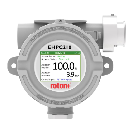
EHPC210 Universal Controller
Controller Firmware Manual v4.25
Bifold – ALL RIGHTS RESERVED
The copyright in this document, which contains information of a proprietary and confidential nature, is vested in Bifold. The content of this document may not
be used for purposes other than that for which it has been supplied and may not be reproduced, either wholly or in part, nor may it be used by, or its contents
divulged to, any other person whosoever, without written permission of Bifold.
Advertisement
Table of Contents

Subscribe to Our Youtube Channel
Related Manuals for rotork Bifold EHPC210


Summary of Contents for rotork Bifold EHPC210
- Page 1 EHPC210 Universal Controller Controller Firmware Manual v4.25 Bifold – ALL RIGHTS RESERVED The copyright in this document, which contains information of a proprietary and confidential nature, is vested in Bifold. The content of this document may not be used for purposes other than that for which it has been supplied and may not be reproduced, either wholly or in part, nor may it be used by, or its contents divulged to, any other person whosoever, without written permission of Bifold.
-
Page 2: Table Of Contents
Table of Contents 1. Introduction 1. Introduction …………………………………………………… 2 This manual provides instruction on the setup and analysis of the controller firmware v4.25. 1.1 Using the Mechanical Control Switch …………. 3 1.2 Passcode Security ………………………………………. 5 Section 1 details how to use the mechanical control switch, 2. -
Page 3: Using The Mechanical Control Switch
1.1 Using the Mechanical Control Switch SWITCH OPERATION MENU NAVIGATION The mechanical control switch is used to operate the The control switch is used for navigating all menus, selecting controller in local mode, navigate through menus, change and changing choices, entering any selection windows and settings and view diagnostic data stored on the controller. - Page 4 When the title of a frame is highlighted, pushing the switch will enter into the frame and turning the switch away and towards will only cycle through the items in the frame. To exit out of a frame the switch should be held away for more than two seconds.
-
Page 5: Passcode Security
If the code has been entered incorrectly then the following 1.2 Passcode Security screen will be displayed and the controller will return to Passcode security can be included in the controller Local mode: application to prevent unauthorised access to the menus and functions within the controller. -
Page 6: Menu
2 Menu 2.1 Application 2. Menu The application section is used to setup the controller to 3.1 Application function as required. 3.1.1 Physical I/O 2.1.1 Physical I/O 3.1.1.1 Digital Inputs Physical inputs and outputs are those wired directly to the 3.1.1.2 Digital Outputs controller. -
Page 7: Digital Inputs
2.1.1 Physical I/O cont. 2.1.1.1 Digital Inputs Analogue Inputs, Analogue Outputs and Internal Sensors are A digital input is a 24V on/off signal which is wired into the all analogue signals and as such each signal provides an controller. If a 24V signal is present the signal is high, if analogue value scaled based on its sensor range. -
Page 8: Digital Outputs
2.1.1.2 Digital Outputs 2.1.1.3 Isolated Inputs A digital output is a 24V on/off signal which is wired out of An isolated input is a relay contact which detects the the controller. When the output is high 24V is provided, presence of a 24V signal but does not have the ability to when the output is low 0V is provided. -
Page 9: Relay Outputs
2.1.1.6 Relay Outputs 2.1.1.5 Analogue Inputs A relay output is a volt free contact and can be used to An analogue input is an analogue signal provided to the switch a 24VDC signal. If the output is high, the relay is controller. -
Page 10: Analogue Outputs
2.1.1.6 Analogue Outputs 2.1.1.7 Internal Sensor An analogue output is an analogue signal calculated and The internal sensor in the controller is a contactless position transmitted by the controller. Both current (4-20mA) and sensor which measures the internal position of the shaft. voltage (0-5V) signals can be provided. -
Page 11: System Data
2.1.2 System Data System data is used to drive the operation of the controller. Any input, output, value or time required to drive the control functions are set up in this section. All physical inputs and outputs are linked to either System Inputs, System Outputs or System Values. -
Page 12: System Inputs
2.1.2.1 System Inputs 2.1.2.2 System Outputs A system input is any digital signal that is used as an input to A system output is any digital signal that is created as an the controller functions. output from the controller functions. A system input can be linked to a digital input or isolated A system output can be linked to a digital output or relay input. -
Page 13: System Values
2.1.2.3 System Values 2.1.2.4 System Times A system value is any analogue signal or value that is A system time is any time period which is required for use in required for use in the controller functions. the controller functions. A system value can be linked to an analogue input or Each time period is set as a number of days, hours, minutes, internal sensor. -
Page 14: Diagnostics
2.2 Diagnostics 2.2.1 Diagnostics – Run Test Diagnostic tests may be included in the application in order If applicable, a diagnostic test can be started manually from to perform a specified test sequence which is used to the controller menus by navigating to the required test and determine whether the system is operating as expected. - Page 15 Failure Code (read-only) 2.2.2 Diagnostics – Test Results The code indicating the reason why the test failed. A value Selecting “Test Results” in the diagnostics screen will display of zero is shown if the test passed, a value of 254 is shown if the following screen.
-
Page 16: Test Results
2.2.2 Diagnostics – Test Results cont. 2.3 Data Logging Data logging is included in the controller to provide details If viewing a “Current” test result then an extra two options of historical operation. are available to select as shown in the following screen. The following screen displays the options available for data NOTE: these extra options are hidden if viewing a “Master”... -
Page 17: Change Log
New Value (read-only) 2.3.1 Change Log The new value that was saved. When the change log option is selected a screen is displayed Method (read-only) showing the list of change logs. The most recent change log This details how the change was made. There are three is listed at the top. -
Page 18: Event Log
Time (read-only) 2.3.2 Event Log The time that the event occurred. When the event log option is selected a screen is displayed Duration (read-only) showing the list of event logs. The most recent event is How long the event lasted. Note if the event is still active listed at the top. -
Page 19: Settings
2.4 Settings 2.4.1 Date and Time cont. Year Current year. Note 18 means 2018, 19 means 2019 etc. Month Current month. Current day. Weekday Current weekday. 2.4.1 Date and Time Date Format The date and time can be set manually, along with the date Required date format. -
Page 20: Display
2.4.2 Display 2.4.3 Communications A number of options can be changed to affect how the main display operates. The following screen displays the available options. 2.4.3.1 HART Screen Update In this section any details regarding HART communication This determines how often the main screen updates. In this can be viewed/changed. -
Page 21: Modbus
2.4.3.2 Modbus 2.4.4 About In this section any details regarding Modbus communication In this section any details about the controller can be can be viewed/changed. viewed. An example of the Modbus screen is displayed below. An example of the About screen is displayed below. Slave Address Address used to communicate with the controller. -
Page 22: Calibration
ANALOGUE INPUT / INTENRAL SENSOR 3 Calibration If calibrating an analogue input or internal sensor the Each physical analogue signal must be calibrated to controller will revert to input calibration mode which means determine the raw signal data at both the minimum and that when the switch is turned away, the actuator will drive maximum ends of its required range.
Need help?
Do you have a question about the Bifold EHPC210 and is the answer not in the manual?
Questions and answers