Sign In
Upload
Download
Table of Contents
Contents
Add to my manuals
Delete from my manuals
Share
URL of this page:
HTML Link:
Bookmark this page
Add
Manual will be automatically added to "My Manuals"
Print this page
×
Bookmark added
×
Added to my manuals
Manuals
Brands
rotork Manuals
Controller
LA-2400 Series
Instruction manual
rotork LA-2400 Series Instruction Manual
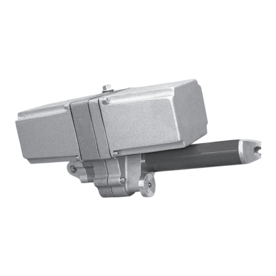
Linear actuators
Hide thumbs
1
Table Of Contents
2
3
4
5
6
7
8
9
10
11
12
13
14
15
16
17
18
19
20
21
22
23
24
25
26
27
28
page
of
28
Go
/
28
Contents
Table of Contents
Troubleshooting
Bookmarks
Table of Contents
Table of Contents
General Information
Introduction
Receiving/Inspection
Storage
Equipment Return
Identification Label
Abbreviations Used in this Manual
General Actuator Description
Basic Models
Product Specifications
Installation
Typical Wiring Diagrams
Typical Wiring Diagram
Start-Up/Calibration
Start-Up/Calibration for Units with Amplifier
Amplifier Specifications
Amplifier Start-Up
Amplifier Parts Identification
Amplifier DIP Switch Chart
Typical Amplifier Wiring Diagram
Amplifier Troubleshooting Chart
Troubleshooting Guide
Component Identification
Component Location Drawing
Maintenance, Gear and Drive Nut Selection
Parts List and Recommended Spares
Installation Dimensions
Major Dimensions
Advertisement
Quick Links
Download this manual
LA-2400
Series
Installation Manual
Linear Actuators
Redefining Flow Control
Table of
Contents
Previous
Page
Next
Page
1
2
3
4
5
Advertisement
Table of Contents
Troubleshooting
Typical Amplifier Wiring Diagram
14
Troubleshooting Guide
15
Need help?
Do you have a question about the LA-2400 Series and is the answer not in the manual?
Ask a question
Questions and answers
Related Manuals for rotork LA-2400 Series
Controller rotork LP/S Series Installation, Comissioning And Maintenance Manual
Pneumatic actuator. single-acting configuration (90 pages)
Controller rotork 1000 Series Installation Manual
Linear actuator (28 pages)
Controller rotork LA-2410 Instruction Manual
Linear actuators (28 pages)
Controller rotork LA-2500 Series Instruction Manual
Linear actuators (40 pages)
Controller rotork LA-2600 Series Installation Manual
Linear actuators (12 pages)
Controller Rotork CML-250 Installation & Maintenance Instructions Manual
Linear, rotary and quarter-turn control valve actuators (61 pages)
Controller rotork IQ Range Full Configuration, Status And Monitoring User Manual
Electric valve actuators (68 pages)
Controller rotork IQT Series Installation And Maintenance Instructions Manual
(88 pages)
Controller rotork IQ Series Manual
(9 pages)
Controller rotork IQT Installation And Maintenance Information
(92 pages)
Controller rotork CMA Series Installation & Maintenance Instructions Manual
Linear, rotary and quarter-turn control valve actuators (64 pages)
Controller rotork IQ3 Instructions For Safe Use, Installation, Basic Setup And Maintenance
(36 pages)
Controller Rotork CVL 500 Installation And Maintenance Instructions Manual
Electric actuators and control systems (50 pages)
Controller Rotork GT Series Installation, Commissioning And Maintenance Manual
Pneumatic actuator, single-acting and double-acting configuration (36 pages)
Controller rotork CK Series Use And Installation Manual
Modular design electric valve actuators (32 pages)
Controller Rotork Skilmatic SI Series User Manual
Electro-hydraulic valve actuators (66 pages)
This manual is also suitable for:
La-2410
La-2415
La-2450
La-2420
La-2490
La-2440
Table of Contents
Print
Rename the bookmark
Delete bookmark?
Delete from my manuals?
Login
Sign In
OR
Sign in with Facebook
Sign in with Google
Upload manual
Upload from disk
Upload from URL


Need help?
Do you have a question about the LA-2400 Series and is the answer not in the manual?
Questions and answers