
Related Manuals for Rockwell Automation Allen-Bradley Guardmaster 440C-CR30


Summary of Contents for Rockwell Automation Allen-Bradley Guardmaster 440C-CR30
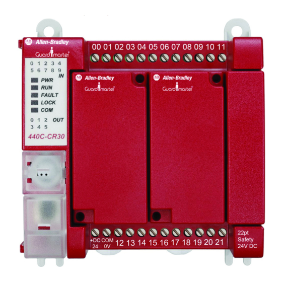
- Page 1 Wiring Diagram Guardmaster 440C-CR30 Configurable Safety Relay Catalog Numbers 440C-CR30-22BBB...
-
Page 2: Powerflex
If this equipment is used in a manner not specified by the manufacturer, the protection provided by the equipment may be impaired. In no event will Rockwell Automation, Inc. be responsible or liable for indirect or consequential damages resulting from the use or application of this equipment. -
Page 3: Additional Resources
Provides declarations of conformity, certificates, and other certification details. You can view or download publications at http:/www.rockwellautomation.com/literature/. To order paper copies of technical documentation, contact your local Allen-Bradley® distributor or Rockwell Automation sales representative. Rockwell Automation Publication 440C-WD001A-EN-P - November 2014... - Page 4 Preface Notes: Rockwell Automation Publication 440C-WD001A-EN-P - November 2014...
-
Page 5: Table Of Contents
Safety Rating ........... . 21 Rockwell Automation Publication 440C-WD001A-EN-P - November 2014... - Page 6 Safety Rating ........... . . 44 Rockwell Automation Publication 440C-WD001A-EN-P - November 2014...
- Page 7 Safety Rating ........... . 49 Rockwell Automation Publication 440C-WD001A-EN-P - November 2014...
- Page 8 Table of Contents Notes: Rockwell Automation Publication 440C-WD001A-EN-P - November 2014...
-
Page 9: Product Overview
For partial body access, the 440G-LZ can be substituted for the TLS-ZR. Product Overview Figure 1 - Overview Rockwell Automation Publication 440C-WD001A-EN-P - November 2014... -
Page 10: Schematic
Stop and Clear Fault P046 Start Source Digital Input Terminal Block P047 Speed Reference Drive Pot T081 Relay 2 Motor Running Motor is receiving power from the drive. T105 Safety Open En Fault Disable Rockwell Automation Publication 440C-WD001A-EN-P - November 2014... -
Page 11: Connected Components Workbench
The operator can access the hazard area. 5. Close the gate. 6. Rotate the Unlock switch to the locked (open) position. This locks the gate and the safety system is ready for reset. Go to Step 1. Rockwell Automation Publication 440C-WD001A-EN-P - November 2014... -
Page 12: Example Bill Of Materials
SIL CL2 per IEC 61061:2012 and SIL 2 per IEC 61508:2005 and has a Category 3 structure that can be used in systems requiring Performance Levels up to PLd per ISO 13849-1: 2006. The circuit executes a Category 1 stop. Rockwell Automation Publication 440C-WD001A-EN-P - November 2014... -
Page 13: Product Overview
An E-stop button is also available at the control panel. Any of the three devices must cause the machine to go to a safe OFF state. Product Overview Figure 4 - Overview Rockwell Automation Publication 440C-WD001A-EN-P - November 2014... -
Page 14: Schematic
Stop and Clear Fault P046 Start Source Digital Input Terminal Block P047 Speed Reference 1 1 Drive Pot T081 Relay 2 Motor Running Motor is receiving power from the drive. T105 Safety Fault En Fault Enable Rockwell Automation Publication 440C-WD001A-EN-P - November 2014... -
Page 15: Connected Components Workbench
The CR30 safety outputs at terminal 17, 18 and 19 are ON. – Clear the light curtain, The PF525 still shows an F059 fault. The motor remains – Close the gate switch, or off. – Release the E-stop. Go to Step 1. Rockwell Automation Publication 440C-WD001A-EN-P - November 2014... -
Page 16: Example Bill Of Materials
ISO 14119. The safety function that is initiated by the E-stop can meet up to Cat 3 PLd per IS013849-1, SIL CL2 per IEC 62061, and SIL 2 per IEC 61508. Rockwell Automation Publication 440C-WD001A-EN-P - November 2014... -
Page 17: Product Overview
Note: The outputs of the CR30 are driving 100S contactors. Due to the inrush current limitations of the CR30, the CR30 can only switch the 100S-C09EJ contactors. The CR30 cannot switch the C43EJ contactors. Product Overview Figure 7 - Overview Rockwell Automation Publication 440C-WD001A-EN-P - November 2014... -
Page 18: Schematic
10 11 I-00 I-01 +24DC O-00 O-01 CR30 440C-CR30-22BBB 2080-IQ4OB4 12 13 14 20 21 I-02 I-03 -24DC O-02 O-03 Zone 1 K1 K2 K3 K4 Zone 2 24V Com Zone 1 Zone 2 Rockwell Automation Publication 440C-WD001A-EN-P - November 2014... -
Page 19: Connected Components Workbench
Safety Mats - Two Zones Chapter 3 Connected Components Figure 9 - Connected Components Workbench Example Workbench Rockwell Automation Publication 440C-WD001A-EN-P - November 2014... -
Page 20: Circuit Status
IS013849-1, SIL CL2 per IEC 62061, and SIL 2 per IEC 61508. The safety function that is initiated by the E-stops can meet up to Cat 4, PLe and SIL3 per IEC61508 and SIL CL3 per IEC 62061. Rockwell Automation Publication 440C-WD001A-EN-P - November 2014... -
Page 21: Product Overview
GripSwitch is used. This application has four distinct safety-related functions: 1. Interlock 'Logic' Drive 2. Enabling Switch 'Logic' Drive 3. Selector switch 'Logic' Drive 4. Jog Switch 'Logic' Drive Product Overview Figure 10 - Overview Rockwell Automation Publication 440C-WD001A-EN-P - November 2014... -
Page 22: Schematic
2 Start 4 Gnd 7 Clear Fault 8 Jog Gate control 03 04 10 11 power supply GripSwitch CR30 Gate control SensaGuard 12 13 14 20 21 circuit Integrated Latch Gate Open 24V Com Rockwell Automation Publication 440C-WD001A-EN-P - November 2014... -
Page 23: Connected Components Workbench
If the jog button is released sooner than 2.5 seconds, the motor stops immediately. Circuit Status The safety gate is closed. The selector switch is set to Gate Switch. The GripSwitch is off and the Jog switch is off. The PF525 is off. Rockwell Automation Publication 440C-WD001A-EN-P - November 2014... -
Page 24: Operational Sequence
Standard trim, 1000 x 1800 mm 100S-C09EJ14BC MCS 100S-C Safety Contactor 9 A, 24V DC (with elec. coil), bifurated contact 800FM-P7MN3W 800F Pilot Light Rd. metal (IP66, 4/13, IP66), clear, standard pack (Qty. 1) Rockwell Automation Publication 440C-WD001A-EN-P - November 2014... -
Page 25: Safety Rating
4. Jog Switch-> Logic -> Drive The safety function that is performed by the jog switch can meet the requirements up to Cat 2 PLc per ISO13849-1, SIL CL1 per IEC62061, and SIL 1 per IEC61508. Rockwell Automation Publication 440C-WD001A-EN-P - November 2014... - Page 26 Chapter 4 Enabling Switch (GripSwitch) with Jog Function Notes: Rockwell Automation Publication 440C-WD001A-EN-P - November 2014...
- Page 27 1, muting sensor 2, and the light curtain. Figure 14 - Machine Layout Hazard Area Non-hazard Area MS1 MS2 Conveyor Flow Material Muting Lamp Rockwell Automation Publication 440C-WD001A-EN-P - November 2014...
-
Page 28: Schematic
3 4 1 3 4 1 Pink OSSD A Grey OSSD B Override Blue Blue 03 04 10 11 CR30 12 13 14 20 21 Contactors Muting for Conveyor Lamp Power 24V Com Rockwell Automation Publication 440C-WD001A-EN-P - November 2014... -
Page 29: Connected Components Workbench
Muting 2-Sensor L-Type Unidirectional Chapter 5 Connected Components Figure 16 - Connected Components Workbench Example Workbench Circuit Status The circuit is ready to run. The muting sensors are clear and the light curtain is clear. Rockwell Automation Publication 440C-WD001A-EN-P - November 2014... -
Page 30: Operational Sequence
An operator can press and hold down the override button for the duration of the override time. The conveyor contactors turn on until the override time expires (or the operator releases the button). Rockwell Automation Publication 440C-WD001A-EN-P - November 2014... -
Page 31: Example Bill Of Materials
9 A, 24V DC (with elec. coil), bifurcated contact Safety Rating The 2-sensor L-type muting meets the performance requirements of Cat 4, PLe per ISO13849-1, SIL CL3 per IEC 62061, and SIL 3 per IEC 61508. Rockwell Automation Publication 440C-WD001A-EN-P - November 2014... - Page 32 Chapter 5 Muting 2-Sensor L-Type Unidirectional Notes: Rockwell Automation Publication 440C-WD001A-EN-P - November 2014...
- Page 33 The function block contains timing parameters that allow you to accommodate a wide range of operating speeds. Product Overview Figure 18 - Overview Rockwell Automation Publication 440C-WD001A-EN-P - November 2014...
- Page 34 3 4 1 3 4 1 Pink OSSD A Grey OSSD B Override Blue Blue 03 04 10 11 CR30 12 13 14 20 21 Contactors Muting for Conveyor Lamp Power 24V Com Rockwell Automation Publication 440C-WD001A-EN-P - November 2014...
-
Page 35: Connected Components Workbench
Muting 2-Sensor T-Type Bidirectional Chapter 6 Connected Components Figure 21 - Connected Components Workbench Example Workbench The circuit is ready to run. The muting sensors are clear and the light curtain is Circuit Status clear. Rockwell Automation Publication 440C-WD001A-EN-P - November 2014... -
Page 36: Operational Sequence
An operator can press and hold down the override button for the duration of the override time. The conveyor contactors turn on until the override time expires (or the operator releases the button). Rockwell Automation Publication 440C-WD001A-EN-P - November 2014... -
Page 37: Example Bill Of Materials
9 A, 24V DC (with elec. coil), bifuracated contact Safety Rating The 2-sensor T-type muting meets the performance requirements of Cat 4, PLe per ISO13849-1, SIL CL3 per IEC 62061, and SIL 3 per IEC 61508. Rockwell Automation Publication 440C-WD001A-EN-P - November 2014... - Page 38 Chapter 6 Muting 2-Sensor T-Type Bidirectional Notes: Rockwell Automation Publication 440C-WD001A-EN-P - November 2014...
- Page 39 The function block contains timing parameters that allow you to accommodate a wide range of operating speeds. Product Overview Figure 23 - Overview Rockwell Automation Publication 440C-WD001A-EN-P - November 2014...
- Page 40 Light Curtain 3 4 1 3 4 1 Pink OSSD A Grey OSSD B Blue Blue 03 04 10 11 CR30 12 13 14 20 21 Contactors Muting for Conveyor Lamp Power 24V Com Rockwell Automation Publication 440C-WD001A-EN-P - November 2014...
-
Page 41: Connected Components Workbench
Connected Components Workbench function block. In addition, the material must move through the light curtain within the muting time, which is also set in the Connected Components Workbench function block. Rockwell Automation Publication 440C-WD001A-EN-P - November 2014... - Page 42 An operator can press and hold down the override button for the duration of the override time. The conveyor contactors turn on until the override time expires (or the operator releases the button). Rockwell Automation Publication 440C-WD001A-EN-P - November 2014...
-
Page 43: Example Bill Of Materials
9 A, 24V DC (with elec. coil), bifuracated contact Safety Rating The 2-sensor L-type muting meets the performance requirements of Cat 4, PLe per ISO13849-1, SIL CL3 per IEC 62061, and SIL 3 per IEC 61508. Rockwell Automation Publication 440C-WD001A-EN-P - November 2014... - Page 44 Chapter 7 Muting 4-sensor T-type Bidirectional Notes: Rockwell Automation Publication 440C-WD001A-EN-P - November 2014...
-
Page 45: Product Overview
Two SensaGuard™ non-contact switches with integrated latch are included in the example to show that the SWS signals can be incorporated into the logic that is performed by the CR30. Product Overview Figure 28 - Overview Rockwell Automation Publication 440C-WD001A-EN-P - November 2014... -
Page 46: Schematic
The Connected Components Workbench shows two safety functions: Workbench 1. SWS In #1 & Gate #1 → SWS Out #1 (Immediate OFF). 2. SWS In #2 & Gate #2 → SWS Out #2 (Delayed OFF). Rockwell Automation Publication 440C-WD001A-EN-P - November 2014... -
Page 47: Circuit Status
Press Reset #2 to activate SWS output #2 (terminal 21). Deactivating SWS In #1 on terminal 10 or opening Gate #1 turns off SWS output #1. Deactivating SWS In #2 on terminal 11 or opening Gate #2 turns off WS output #2. Rockwell Automation Publication 440C-WD001A-EN-P - November 2014... -
Page 48: Example Bill Of Materials
The safety ratings of the two safety functions depend on additional components Safety Rating that are not included in the example. The SWS portion of the circuit can be used in applications up to Cat 4 PLe and SIL3. Rockwell Automation Publication 440C-WD001A-EN-P - November 2014... -
Page 49: Product Overview
The application uses pulse testing to check for potential short circuits to 24V, ground and across channels. Manual monitored reset prevents the outputs from turning ON when Lifeline switches are reset. Product Overview Figure 31 - Overview Rockwell Automation Publication 440C-WD001A-EN-P - November 2014... -
Page 50: Schematic
MCS 100S-C Safety Contactor 9 A, 24V DC (with elec. coil), bifurcated contact Safety Rating The safety rating that is initiated by either cable pull switch meets the requirements of Cat 4 PLe and SIL3. Rockwell Automation Publication 440C-WD001A-EN-P - November 2014... -
Page 51: Schematic
Figure 34 - Schematic +24V DC Blue Brown Blue Brown Blue Brown White Black Grey Blue Brown White Black Grey 03 04 10 11 CR30 12 13 14 20 21 K3 K4 24V Com Rockwell Automation Publication 440C-WD001A-EN-P - November 2014... -
Page 52: Circuit Status
K2 (or K3 and K4), where simultaneously means within a half second of each other. You must maintain their hands on both buttons to maintain the contactors in the ON state. Removing your hands from either button causes the contactors to turn OFF. Rockwell Automation Publication 440C-WD001A-EN-P - November 2014... -
Page 53: Example Bill Of Materials
30.5 mm mounting hole, 12 ft length 100S-C09EJ23BC MCS 100S-C Safety Contactor 9 A, 24V DC (with elec. coil), bifurcated contact Safety Rating Although the wiring is a little different, both 2-hand control systems meet ISO13851 Type IIIC. Rockwell Automation Publication 440C-WD001A-EN-P - November 2014... - Page 54 Chapter 10 Two-hand Control Notes: Rockwell Automation Publication 440C-WD001A-EN-P - November 2014...
- Page 56 New Product Satisfaction Return Rockwell Automation tests all of its products to help ensure that they are fully operational when shipped from the manufacturing facility. However, if your product is not functioning and needs to be returned, follow these procedures.
Need help?
Do you have a question about the Allen-Bradley Guardmaster 440C-CR30 and is the answer not in the manual?
Questions and answers