
Related Manuals for Rockwell Automation Allen-Bradley 836P Series


Summary of Contents for Rockwell Automation Allen-Bradley 836P Series
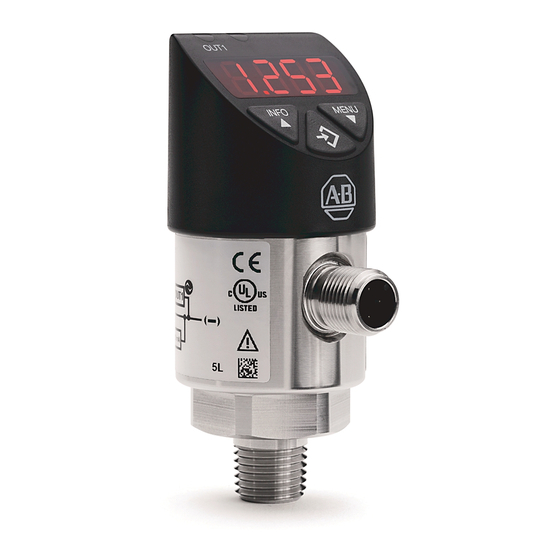
- Page 1 User Manual Original Instructions IO-Link for Solid-state Pressure Switches Catalog Number 836P-Dx...
- Page 2 If this equipment is used in a manner not specified by the manufacturer, the protection provided by the equipment may be impaired. In no event will Rockwell Automation, Inc. be responsible or liable for indirect or consequential damages resulting from the use or application of this equipment.
-
Page 3: Table Of Contents
Configuration Procedure ........23 Rockwell Automation Publication IOLINK-UM001A-EN-P - August 2017... - Page 4 Index ............43 Rockwell Automation Publication IOLINK-UM001A-EN-P - August 2017...
-
Page 5: Preface
836P pressure switch. For detailed 836P pressure switch information, see 836P-UM001. Overview and Benefits Rockwell Automation is the only supplier who provides every piece of the Connected Enterprise solution. Plus, exclusive features, and Premier Integration between Allen-Bradley® components and an Integrated Architecture®... -
Page 6: Additional Resources
Provides declarations of conformity, certificates, and www.rockwellautomation.com/global/certification/ other certification details. overview.page You can view or download publications at http://www.rockwellautomation.com/global/literature-library/overview.page. To order paper copies of technical documentation, contact your local Allen-Bradley distributor or Rockwell Automation sales representative. Rockwell Automation Publication IOLINK-UM001A-EN-P - August 2017... -
Page 7: What Is Io-Link
• No special cables required • Connectivity options remain the same • Access IO-Link functionality by simply connecting an IO-Link enabled device to an IO-Link master • Analog devices no longer require a dedicated input card Rockwell Automation Publication IOLINK-UM001A-EN-P - August 2017... -
Page 8: Real-Time Diagnostics And Trends
In this case, it is possible to monitor or configure the sensor through IO-Link on pin 4 of the sensors while connecting pin 2 (if the sensor offers a second output) of the sensor to a standard input card. Rockwell Automation Publication IOLINK-UM001A-EN-P - August 2017... -
Page 9: Transmission Rates
IO-Link Data Types There are four data types available through IO-Link: Process data Cyclic data → Value status Cyclic data → Device data Acyclic data → Events Acyclic data → Rockwell Automation Publication IOLINK-UM001A-EN-P - August 2017... -
Page 10: Process Data
The controller accesses these using Explicit Messaging. The use of the index and subindex ranges allows targeted access to the device data (for example, for reassigning the device or master parameters during operation). Rockwell Automation Publication IOLINK-UM001A-EN-P - August 2017... -
Page 11: Start Up Of The I/O System
(portable network graphics). These files adhere to the IO-Link open standard, which means that they can be used with any IO-Link masters. IODD files are assigned using Studio 5000® and the 1734-4IOL Add-on Profile (AOP). (1) When using the 1734-4IOL IO-Link master module. Rockwell Automation Publication IOLINK-UM001A-EN-P - August 2017... -
Page 12: Premier Integration
Sensors (Requires two IO-Link Masters To simplify the integration of the Rockwell Automation® IO-Link devices to the Rockwell Automation architecture, there is an IO-Link AOP available for the 1734-4IOL master module. The use of an AOP simplifies the setup of devices by providing the necessary fields in an organized manner. -
Page 13: 836P Io-Link Features
The name resides in the project and the sensor itself. • Tag Naming for I/O Data: Rockwell Automation system solutions provide tag names that are based on the Allen-Bradley sensor connected. I/O data is converted, formatted, and named based on the Allen-Bradley sensor applied. - Page 14 Chapter 1 836P Pressure Sensor with IO-Link Overview Notes: Rockwell Automation Publication IOLINK-UM001A-EN-P - August 2017...
-
Page 15: Hardware
• 889D cordsets: 889D-F4AC-5x (IO-Link maximum acceptable cable length is 20 m (65.6 ft)) Software Required: • Studio 5000® environments, version 20 and higher • Sensor-specific IODD • 1734-4IOL IO-Link Add-on Profile (AOP) Rockwell Automation Publication IOLINK-UM001A-EN-P - August 2017... -
Page 16: Example: Set Up The Hardware
4. Wire the sensor cable to the desired location on the IO-Link master (in this example, we are showing the sensor that is wired to the channel 0). 5. Connect the 836P to the other end of the sensor cable. Rockwell Automation Publication IOLINK-UM001A-EN-P - August 2017... - Page 17 Controller Organizer Tree and the 836P has been wired to the master module, the green status indicator on the sensor flashes at a 1 Hz rate. This flash indicates that it is operating in IO-Link mode. Rockwell Automation Publication IOLINK-UM001A-EN-P - August 2017...
- Page 18 Chapter 2 Set up the 836P Sensor for IO-Link Mode Notes: Rockwell Automation Publication IOLINK-UM001A-EN-P - August 2017...
-
Page 19: Begin A New Project
Link Master on page 1. Double-click the Studio 5000 icon. 2. Click New Project. 3. To program the controller, select the controller that is used. In this example, it is the “1769 L24ER” CompactLogix. Rockwell Automation Publication IOLINK-UM001A-EN-P - August 2017... - Page 20 “Project836P.” Project836P 5. Once the project opens up, configure the IP address of the controller to help ensure communication. To configure the IP address, click the browsing icon. Rockwell Automation Publication IOLINK-UM001A-EN-P - August 2017...
-
Page 21: Aop Installation
20 or higher of Studio 5000 supports this module and AOP. To confirm that the 1734-4IOL is installed, verify that the 1734 AENT(R) contains the 1734-4IOL in the library. To download the AOP, see Install the Add-on Profile on page 33 for more information. Rockwell Automation Publication IOLINK-UM001A-EN-P - August 2017... - Page 22 Chapter 3 Create a Project Notes: Rockwell Automation Publication IOLINK-UM001A-EN-P - August 2017...
-
Page 23: Configuration Procedure
Configure the IO-Link Master Configuration Procedure 1. Verify that the controller is offline to configure the IO-Link Master. 2. In the controller organizer tree, find Ethernet under I/O Configuration. Right-click Ethernet and select New Module. Rockwell Automation Publication IOLINK-UM001A-EN-P - August 2017... - Page 24 Create. 4. Name the Ethernet adapter (in this example our adapter name is “adapter”), set the chassis size, check the module revision and setup the adapter IP address. Click OK and then Close. Rockwell Automation Publication IOLINK-UM001A-EN-P - August 2017...
- Page 25 Configure the IO-Link Master Chapter 4 5. The 1734 AENTR now appears in the Controller Organizer tree. 6. Right-click on 1734-AENTR adapter, and select New Module. Rockwell Automation Publication IOLINK-UM001A-EN-P - August 2017...
- Page 26 You can now configure your 836P pressure switch. To configure the sensor, a sensor-specific IODD (I/O Device Description) file is required. The next steps show how to register the IODD file (page 27). Rockwell Automation Publication IOLINK-UM001A-EN-P - August 2017...
-
Page 27: Registration Procedure
MultiProductDownload.aspx. Once the IODD is registered, there is no need to register the IODD again unless it is manually deleted from the Master Tree. 1. Double-click the 1734-4IOL in the Controller Organizer Tree. 2. Select the IO-Link configuration tab. Rockwell Automation Publication IOLINK-UM001A-EN-P - August 2017... - Page 28 Chapter 5 Register the 836P IODD The IO-Link configuration screen appears. 3. Right-click the left section of the screen where the channel information is located and click Register IODD. Rockwell Automation Publication IOLINK-UM001A-EN-P - August 2017...
- Page 29 4. Click the Register IODD button. A new window appears. Click the Register IODD button of the new window. The new window enables you to locate the IODD file in your computer. 5. Click Exit. The IODD registration is complete. Rockwell Automation Publication IOLINK-UM001A-EN-P - August 2017...
- Page 30 Chapter 5 Register the 836P IODD Notes: Rockwell Automation Publication IOLINK-UM001A-EN-P - August 2017...
-
Page 31: Connection Procedure
The controller must always be off line to add a device to the IO-Link master. 1. Right-click the channel number where the sensor is configured and select Change. 2. Click … to select the appropriate sensor. Rockwell Automation Publication IOLINK-UM001A-EN-P - August 2017... - Page 32 3. Select the appropriate sensor and double-click or click Create. 4. Click OK to accept the configuration. 5. Click Go Online to communicate. Publication 836P-UM001 describes each tab of the 1734-4IOL AOP in detail and how to teach the sensor. Rockwell Automation Publication IOLINK-UM001A-EN-P - August 2017...
-
Page 33: Introduction
RSLogix 5000® program. AOPs are files that you add to your Rockwell Automation® library. These files contain the pertinent information for configuring a device that is added to the Rockwell Automation network. The AOP simplifies the setup of devices because it presents the necessary fields in an organized fashion. - Page 34 Appendix A Install the Add-on Profile 3. Click Next to install the IO-Link module profiles. 4. Accept the license agreements and click Next. 5. Follow the module-profiles installation wizard. Rockwell Automation Publication IOLINK-UM001A-EN-P - August 2017...
- Page 35 Install the Add-on Profile Appendix A 6. Verify that the Install option is selected and click Next. 7. Review the install details and click “Install.” Rockwell Automation Publication IOLINK-UM001A-EN-P - August 2017...
- Page 36 8. The installation process begins. This process can take several minutes. Once completed the Next button is available. 9. Click Next. 10. Click Finish and review the release notes for any additional information. The IO-Link AOP installation is completed. Rockwell Automation Publication IOLINK-UM001A-EN-P - August 2017...
-
Page 37: Configure A Message Instruction
836P sensor. To complete the dialog box, the Service Code and Source Length must be provided. A table of the different Read and Write Service Codes and their associated Source Lengths are shown on page Rockwell Automation Publication IOLINK-UM001A-EN-P - August 2017... - Page 38 Source Length - This box contains the number of bytes of service data 1 byte to be sent or received in message. Defined in Data Structure Tables. Destination Element - First element of the destination Array. Read_Assembly[0] Rockwell Automation Publication IOLINK-UM001A-EN-P - August 2017...
-
Page 39: Read Data From The Sensor
This example shows the steps necessary to write “Test” to the Application Specific Name index. The source element Array is “Write_Assembly, ” byte zero is the channel followed by the data to be written. Rockwell Automation Publication IOLINK-UM001A-EN-P - August 2017... - Page 40 Source Length - This item contains the number of bytes of service 5 bytes data to be sent or received in message. Defined in Data Structure Tables. Destination Element - Not applicable. — Rockwell Automation Publication IOLINK-UM001A-EN-P - August 2017...
-
Page 41: Validation Of Write
3. Check the Upload checkbox, then click OK and the new parameter values are uploaded into the controller. 4. The new Application Specific Name can be seen when viewing the Identification Tab of the AOP for the 836P sensor. Rockwell Automation Publication IOLINK-UM001A-EN-P - August 2017... -
Page 42: Service Code
Table 6 - Write Index (4E) - Message Data Format Byte 0 Byte 1 Byte 2 Byte 3 Channel Number Data 0 Data 1 Data 3 Source Length= 1 byte + Number of bytes of data being written Rockwell Automation Publication IOLINK-UM001A-EN-P - August 2017... -
Page 43: Index
8 device data 10 profile 8 overview 5 device parameter IO-Link 7 assign 11 diagnostics real-time 8 process data 10 profile device 8 event 10 example configuration 37 quality transmission 9 Rockwell Automation Publication IOLINK-UM001A-EN-P - August 2017... -
Page 44: Rockwell Automation Publication Iolink-Um001A-En-P - August
I/O system 11 status value 10 structure message 37 descriptive 8 terminology 5 time response 9 transmission quality 9 rate 9 trends 8 value status 10 write message 39 validation 41 Rockwell Automation Publication IOLINK-UM001A-EN-P - August 2017... - Page 46 Rockwell Automation maintains current product environmental information on its website at http://www.rockwellautomation.com/rockwellautomation/about-us/sustainability-ethics/product-environmental-compliance.page. Allen-Bradley, CompactLogix, ControlLogix, Integrated Architecture, POINT I/O, RSLogix 5000, Studio 5000, Studio 5000 Logix Designer, Rockwell Automation, and Rockwell Software are trademarks of Rockwell Automation, Inc. Trademarks not belonging to Rockwell Automation are property of their respective companies.
Need help?
Do you have a question about the Allen-Bradley 836P Series and is the answer not in the manual?
Questions and answers