Table of Contents
Advertisement
Advertisement
Table of Contents

Subscribe to Our Youtube Channel
Related Manuals for HIKVISION DS-K1T606 series


Summary of Contents for HIKVISION DS-K1T606 series
- Page 1 Face Recognition Terminal User Manual...
-
Page 2: About This Manual
BUSINESS PROFITS, BUSINESS INTERRUPTION, OR LOSS OF DATA OR DOCUMENTATION, IN CONNECTION WITH THE USE OF THIS PRODUCT, EVEN IF HIKVISION HAS BEEN ADVISED OF THE POSSIBILITY OF SUCH DAMAGES. REGARDING TO THE PRODUCT WITH INTERNET ACCESS, THE USE OF PRODUCT SHALL BE WHOLLY AT YOUR OWN RISKS. - Page 3 Regulatory Information FCC Information Please take attention that changes or modification not expressly approved by the party responsible for compliance could void the user’s authority to operate the equipment. FCC Compliance: This equipment has been tested and found to comply with the limits for a Class A digital device, pursuant to part 15 of the FCC Rules.
- Page 4 What Information We Collect In order to provide HIKVISION services to you, we will ask you to provide personal information that is necessary to provide those services to you. If you do not provide your personal information, we may not be able to provide you with our products or services.
- Page 5 Here are some examples of the personal information we may collect and how we may use it: • When you create your account to use HIKVISION Services (“Account”), we will collect information including your name, phone number, and e-mail and physical address. In addition, when you install and activate Products, we will collect certain basic information via our HIKVISION Services such as your product name, the product’s verification code, and serial number, which are unique to the Product...
- Page 6 Terms of Service. • If HIKVISION and/or all or part of our assets are ever sold or transferred, your personal information may be among the items sold or transferred. Under such circumstance, we will notify you by the e-mail address specified in your account or by means of notice on us.hikvision.com and associated Websites...
- Page 7 HIKVISION generally stores your personal information on HIKVISION’s servers, which is established upon Amazon Servers, until you delete or edit it, or for as long as you remain a HIKVISION customer in order to provide you with the most relevant offers.
- Page 8 Links to Other Websites We may permit others to link to the HIKVISION services or to post a link to their Website. We do not endorse these Websites and are not responsible for other Websites or their privacy practices. Please read their privacy policies before submitting information.
- Page 9 To request a copy of the information disclosure provided by HIKVISION pursuant to Section 1798.83 of the California Civil Code, please contact us at the contact information below in Contact Us. Please allow 30 days for a response.
- Page 10 Ensure your outlets are properly wired. They can be checked with an electrical outlet tester. • Surge Suppressor (Required) Hikvision is not responsible for any damage to equipment caused by power spikes in the electrical power grid. Use of a surge suppressor meeting the following specifications is mandatory for all Hikvision electronic equipment: ˗...
-
Page 11: Safety Instructions
Safety Instructions • Proper configuration of all passwords and other security settings is the responsibility of the installer and/or end user. • In the use of the product, you must be in strict compliance with the electrical safety regulations of the nation and region. -
Page 12: Table Of Contents
Table of Contents Chapter 1 Overview ..........................14 Introduction ..........................14 Main Features ..........................14 Chapter 2 Appearance ..........................15 Chapter 3 Terminal Descriptions ......................16 Chapter 4 Terminal Connection ........................ 18 Chapter 5 Installation ..........................19 Installation with Gang Box ......................19 Installing without Gang Box ...................... - Page 13 Schedule and Template ....................... 96 Week Schedule ........................96 Holiday Group ........................... 97 Template ..........................99 Permission Configuration ......................101 Adding Permission ......................... 102 Applying Permission ......................103 Advanced Functions ......................... 104 Access Control Parameters ....................104 Card Reader Authentication ....................107 Multiple Authentication ......................
-
Page 14: Chapter 1 Overview
Chapter 1 Overview 1.1 Introduction The DS-K1T606 series face recognition terminal is an access control device that is equipped with face recognition functionality. It is mainly deployed as part of secure access control systems, such as logistic centers, airports, university campuses, alarm centrals, dwellings and so on. -
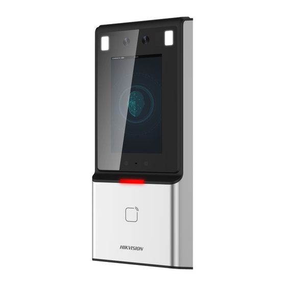
Page 15: Chapter 2 Appearance
Chapter 2 Appearance Refer to the following contents for detailed information on the face recognition terminal: Figure 2-1: Face Recognition Terminal Diagram Table 2-1 Description of Face Recognition Terminal Name Description USB Interface Plug in the USB flash drive to import or export data Loudspeaker Sound emitter Display Screen... -
Page 16: Chapter 3 Terminal Descriptions
Chapter 3 Terminal Descriptions The terminals contain power input, alarm input, alarm output, RS-485, Wiegand output, and door lock. Refer to the following terminal diagram and connection description table for more information: Figure 3-1: Terminal Inputs and Outputs UM DS-K1T606 061719NA... - Page 17 Table 3-1: Terminal Connection Descriptions Group No. Function Color Name Description Group A Power Input +12V 12V DC Power Supply Black Ground Yellow/Blue Alarm Input 1 Alarm Input Yellow/Black Ground Group B Yellow/Orange Alarm Input 2 Yellow/Purple Alarm Output Alarm Output Wiring Yellow/Brown Yellow/Red Yellow...
-
Page 18: Chapter 4 Terminal Connection
Chapter 4 Terminal Connection You can connect the RS-485 terminal to the RS-485 card reader, the NC and COM terminals to the door lock, the SENSOR/BUTTON terminal to the exit button, the alarm output and input terminal to the alarm output/input devices, and the Wiegand terminal to the Wiegand card reader or the access controller. -
Page 19: Chapter 5 Installation
Chapter 5 Installation Installation Environment: If the device is installed indoors, the device should be at least 6.6 ft (2 m) away from the light, and at least 9.8 ft (3 m) away from the window or the door. Ensure that the environment illumination is greater than 100 lux. Appendix C Tips for Installation Environment Note: For details about the installation environment, see... -
Page 20: Installing Without Gang Box
Use two supplied screws to secure the mounting plate to the gang box. Use another four supplied screws to secure the mounting plate to the wall. Route the cables through the cable hole of the mounting plate, and connect to the corresponding external device cables. - Page 21 Figure 5-3: Mounting Template Drill 4 holes on the wall or other surface by following the locations of Hole 1 in the mounting template. Insert the screw sockets of the set screws into the drilled holes. Figure 5-4: Set Screw Diagram UM DS-K1T606 061719NA...
- Page 22 Align the drilled holes with the 4 holes of the mounting plate. Route the cables through the cable hole of the mounting plate, and connect it to the corresponding external device cables. Fix and fasten the screws into the sockets on the wall or other surface. Remove the screw at the bottom of the device.
-
Page 23: Chapter 6 Basic Operation
Chapter 6 Basic Operation 6.1 Activate Device Purpose: Activate the terminal before first use. Activation via device, activation via SADP, and activation via client software are supported. The default values of the control terminal are the following: • Default IP address: 192.0.0.64. •... -
Page 24: Activating Via Sadp Software
Activating via SADP Software Purpose: SADP software is used for detecting an online device, activating the device, and resetting the password. Get the SADP software from the supplied disk or the official website, and install SADP according to the prompts. Follow the steps to activate the device. 1. -
Page 25: Activating Via Client Software
Figure 6-3: Network Parameter Modification 6. Input the password and click Modify to save the IP address. Activating via Client Software Purpose: The client software is a versatile video management software for multiple kinds of devices. Obtain the client software from the supplied disk or the official website, and install the software according to the prompts. - Page 26 Figure 6-4: Device Management Interface 2. Click Device Management to enter the Device Management interface. 3. Check the device status from the device list, and select an inactive device. Figure 6-5: Device List Page 4. Check the device status from the device list, and select an inactive device. 5.
- Page 27 Figure 6-6: Device Activation Password Page 7. Click OK button to start activation. 8. Click the Modify Netinfor button to display the Network Parameter Modification interface. 9. Change the device IP address to the same network segment as your computer by modifying the IP address manually.
-
Page 28: Login
6.2 Login Option 1 If this is your first login, proceed as follows: 1. Tap the settings icon at the lower right corner of the initial page to enter the Input Password page. Figure 6-8: Activation Password Input Page 2. Tap the Password field and input the device activation password. 3. - Page 29 The home page is shown as below: Figure 6-10: Home Page Notes: The device will be locked for 30 minutes after 5 failed password attempts. • • The supported authentication modes are as follows: Face picture or fingerprint, card or password, fingerprint and password, fingerprint and card, face picture and password, face picture and card, card and password, fingerprint, face picture, employee ID and password, card, fingerprint or card, fingerprint or password, card or password, employee ID and fingerprint, fingerprint and card and password, employee ID and fingerprint and...
-
Page 30: General Parameters Settings
6.3 General Parameters Settings Communication Settings Purpose: Set the network parameters, the Wi-Fi parameter, the RS-485 parameters, and the Wiegand parameters on the communication settings page. Tap Comm. (Communication Settings) on the Home page to enter the Communication Settings page. Setting Network Parameters Purpose: Set the device network parameters, including the IP address, the subnet mask, and the gateway. - Page 31 Figure 6-11: Wireless Network Selector 3. Select a Wi-Fi in the list to enter the Wi-Fi parameters settings page. 4. Select an IP mode. If selecting Static, you should input the Wi-Fi password, IP address, subnet mask and gateway. If selecting Dynamic, you should input the Wi-Fi password.
- Page 32 6. Tap to save the Wi-Fi parameters and go back to the Home page. Setting RS-485 Parameters Purpose: The face recognition terminal can connect external secure door control unit or card reader via the RS- 485 terminal. 1. In the Communication Settings page, tap RS-485 to enter the RS-485 tab. Figure 6-13: RS-485 Settings 2.
-
Page 33: System Settings
Transmission Direction: Output: A face recognition terminal can connect to an external access controller. The two devices • will transmit the card number via Wiegand 26 or Wiegand 34 modes. Input: A face recognition terminal can connect to a Wiegand card reader. There is no need to set •... - Page 34 Table 6-1: Description of System Settings Parameter Description Device ID Set the face recognition terminal’s device ID number. The device ID is the DIP address for that is used for communication between the device and the access controller, if the device connects to an access controller via the RS-485 protocol.
- Page 35 Figure 6-16: Face Picture Parameters Table 6-2: Description of Face Picture Parameters Parameter Description 1:N Level Set the matching security level when authenticating via 1:N matching mode. 1:1 Level Set the matching security level when authenticating via 1:1 matching mode. Liveness Level After enabling Live Face Detection function, you can set the matching security level when performing live face authentication.
- Page 36 Setting Fingerprint Parameters Purpose: Set the fingerprint security level in this section. Note: Only the device with the fingerprint scanning function supports the fingerprint related function. Figure 6-17: Security Level Settings Table 6-3: Security Level Description Parameter Description Security Level Set the fingerprint security level.
-
Page 37: Setting Time
Figure 6-18: Device Reboot and Firmware Upgrade Page Setting Time Purpose: Set the device time and the DST in this section. 1. Tap Time (Time Settings) on the Home page to enter the Time Settings page. Figure 6-19: Time Settings Page 2. -
Page 38: Adding User
Figure 6-20: User Management Interface Adding User Purpose: On the Add User page, you can add users, including the employee number, name, and card number. You can also link the fingerprint, the face picture to the user, or set password, authentication mode, schedule template, administrator permission for the user. - Page 39 Note: Only numbers are allowed in the password. • • Up to 8 characters are allowed in the password. 6. Tap the Fingerprint field to enter the Add Fingerprint page. Figure 6-21: Add Fingerprint Page Follow the steps below to add fingerprint. 1) Place your finger on the fingerprint module.
- Page 40 7. Tap the Face Picture field to enter the face picture adding page. Figure 6-22: User Face Picture Addition Follow the steps below to add the user’s face picture. 1) Position your face looking at the camera. Note: Make sure your face picture is in the face picture outline when adding the face picture. After completely adding the face picture, a captured face picture will be displayed on the page.
- Page 41 and tap to save the settings. Note: 7.6 Schedule and Template For details about setting the schedule template, see . After applying the schedule tem plate from the client software to the device, select the corresponding schedule template 10. Tap Authentication Mode to enter the Authentication Mode page. Select Device or Custom as the authentication mode.
-
Page 42: Managing User
12. Enable or disable the Duress Card function. When the function is enabled, the user’s card will be the duress card. When the user authenticates by swiping this duress card, the device will upload a duress card event to the client software. 13. -
Page 43: Setting Access Control Parameters
6.5 Setting Access Control Parameters Purpose: Set the following access control permissions: Reader/Terminal Authentication Mode, Door Magnetic Sensor, Anti-Passback, Lock Locked Time, Door Open Timeout Alarm, and Max. Failed Authentications. 1. On the Home page, tap ACS (Access Control Settings) to enter the Access Control Settings page. Figure 6-25: Access Control Settings 2. -
Page 44: Other Managements
Door Open Timeout The alarm can be triggered if the door has not been closed. The Alarm available door locked time range is 1 to 255 s. Max. Failed Set the maximum authentication times. If authentication fails a Authentications set number of times, the alarm will be triggered. The available door locked time range is 1 to 255 s. -
Page 45: Managing Log Query
The available button descriptions are as follows: Table 6-6: Data Management Function Descriptions Parameter Description Delete All Events Delete all events stored in the device. Delete User Data Delete all user data in the device. Delete All Data: Delete all user data and events stored in the device. Clear Permission Clear the administrator permission. - Page 46 Figure 6-27: Transfer Settings Page Exporting Data 1. Plug a USB flash drive in the device. 2. On the Transfer page, tap one of the following: Export Att. Data, Export User Data, Export User Profile Pic., Export ACS Parameters, or Export Picture (Export Captured Picture). 3.
-
Page 47: Testing
flash drive to Device B. In this case, you should import the user data before importing the profile photo. • The supported USB flash drive format is FAT32. • The imported picture should be saved in the root directory (enroll_pic) and the picture file name should be named according to the following rule: Card No._Name_Department_Employee ID_Gender.jpg •... -
Page 48: Viewing System Information
Table 6-7: Face Functionality Test Descriptions Parameters Description Face Test Position your face looking at the camera and the device will test the face detection function. Voice Test If the voice prompt function is working properly, you will hear the voice prompt “Authenticated”... -
Page 49: Authenticating Identity
Viewing Device Information Purpose: You can view the device model, the serial number, the MAC address, the firmware version, the face algorithm version, the production date, and the fingerprint algorithm version. Tap Device to enter the Device page. Note: The device information page may vary according to different device models. Figure 6-30: System Information Page 6.7 Authenticating Identity Purpose:... -
Page 50: Authenticating Via Other Types
Authenticating via Other Types 1. According to the configured authentication mode, authenticate by comparing face pictures, fingerprints or by swiping card. Stand in front of the device. Position your face looking at the camera and Face Picture the device will enter the face picture authentication mode. Authentication Note: For detailed information about authenticating face picture, see... -
Page 51: Chapter 7 Client Operation
Chapter 7 Client Operation Set and operate the access control devices via the client software. This chapter will introduce the access control device related operations in the client software. For integrated operations, refer to the iVMS-4200 Client Software User Manual 7.1 User Registration and Login Register the super user name and password when using the iVMS-4200 client software for the first time. -
Page 52: System Configuration
iVMS- you add the device and perform other operations. For detailed wizard configuration, refer to the 4200 Quick Start Guide 7.2 System Configuration Purpose: You can synchronize the missed access control events with the client. 1. Click Tool – System Configuration. 2. -
Page 53: Adding Access Control Device
Before you start: When opening the Access Control module for the first time, the following dialog will display and you are required to select the scene according to the actual needs. Non-residence: Set the attendance rule when adding a person, while set the access control parameters. - Page 54 Creating Password Purpose: For some devices, you are required to create a password in order to activate them, before they can be added to the software and work properly. Note: This function should be supported by the device. 1. Enter the Device Management page. 2.
- Page 55 2) Create a verification code. 3) Confirm the verification code. 4) Click Terms of Service and Privacy Policy to read the requirements. 5) Click OK to enable the Hik-Connect service. 6. Click OK to activate the device. A “The device is activated” window displays when the password is set successfully. 7.
- Page 56 1. Select the devices to be added from the list. Note: For inactive devices, create a strong password before adding the device. 2. Click Add to Client to open the device adding dialog box. 3. Input the required information. Nickname: Edit a name for the device. Address: Input the device’s IP address.
- Page 57 Adding Multiple Online Device Ctrl If you want to add multiple online devices to the client software, click and hold the key to select multiple devices, and click Add to Client to open the device adding dialog box. In the pop-up message box, enter the user name and password for the devices to be added.
- Page 58 3) Click Add. When the offline device comes online, the software will connect to it automatically. 5. Click Add to add the device. Figure 7-12: Device Addition Page Adding Devices by IP Segment 1. Click Add to open the device adding dialog box. 2.
- Page 59 2) Input the required information, including the device channel number and alarm input number. 3) Click Add. When the offline device comes online, the software will connect to it automatically. 5. Click Add. You can add the device which the IP address is between the start IP and end IP to the device list. Figure 7-13: Device Addition Page Adding Devices by Hik-Connect Domain Purpose:...
- Page 60 Password: Input the device password. We highly recommend that you create a strong password of your own choosing (using a minimum of eight characters, including at least three of the following categories: upper case letters, lower case letters, numbers, and special characters) in order to increase the security of your product. We also recommend that you reset your password regularly.
- Page 61 Figure 7-15: Device Addition Page 6. Check the appropriate checkbox to select the desired device. 7. Input the user name and password for the devices to be added. 8. Optionally, check the Export to Group checkbox to create a group by the device name. You can import all the channels of the device to the corresponding group by default.
- Page 62 Figure 7-16: Device Addition Page 3. Input the required information. Nickname: Edit a name for the device that you wish to add. Account: Input the account name registered on the EHome protocol. 4. Optionally, check the Export to Group checkbox to create a group according to device name. You can Note: import all the channels of the device to the corresponding group by default.
- Page 63 Figure 7-17: Device Addition Page 3. Input the required information. Nickname: Edit a name for the device that you wish to add. Serial Port No.: Select the device’s connected serial port number. Baud Rate: Input the baud rate of the access control device. DIP: Input the DIP address of the device.
- Page 64 Figure 7-18: Device Addition Page 3. Input the required information. Nickname: Edit a name for the device that you wish to add. Server Address: Input the IP address of the PC that installs the IP Server. Device ID: Input the device ID registered on the IP Server. admin User Name: Input the device user name.
- Page 65 2. Select HiDDNS as the adding mode. Figure 7-19: Device Addition Page 3. Input the required information. Nickname: Edit a name for the device that you wish to add. www.hik-online.com Server Address: Device Domain Name: Input the device domain name registered on HiDDNS server. User Name: Input the device user name.
- Page 66 Importing Devices in Batch Purpose: The devices can be added to the software in batch by inputting the device information in the pre- defined CSV file. 1. Click Add to open the device adding dialog box. 2. Select Batch Import as the adding mode. Figure 7-20: Device Addition Page 3.
-
Page 67: Viewing Device Status
User Name: Input the device user name. The default user name is admin • Password: Input the device password. • We highly recommend that you create a strong password of your own choosing (using a minimum of eight characters, including at least three of the following categories: upper case letters, lower case letters, numbers, and special characters) in order to increase the security of your product. -
Page 68: Editing Basic Information
Figure 7-21: Device Status Page Note: The interface may differ from the picture displayed above. Refer to the actual interface when adopting this function. Door Status: Connected door status Host Status: The status of the host, including Storage Battery Power Voltage, Device Power Supply Status, Multi-door Interlocking Status, Anti-passing Back Status, and Host Anti-Tamper Status. -
Page 69: Network Settings
4. Edit the device information, including the adding mode, the device name, the device IP address, port number, user name, and the password. Network Settings Purpose: After adding the access control device, set the uploading mode, as well as the network center and wireless communication center. - Page 70 Figure 7-23: Network Settings Page 2. Select the center group in the dropdown list. 3. Select the Address Type as IP Address or Domain Name. 4. Input IP address or domain name according to the address type. 5. Input the port number for the protocol. The default port number is 7660. 6.
-
Page 71: Capture Settings
Figure 7-24: Network Settings Page 2. Select the APN name as CMNET or UNINET. 3. Input the SIM Card number. 4. Select the center group in the dropdown list. 5. Input the IP address and port number. 6. Select the protocol type as EHome. By default, the port number for EHome is 7660. 7. -
Page 72: Settings
4. Set the capture interval according to the capture times. 5. Click Save to save the settings. Manual Capture 1. Select the Manual Capture tab. Figure 7-25: Linked Capture Page 2. Select the resolution of the captured pictures from the dropdown list. 3. -
Page 73: Wiegand Settings
3. Select the serial number of the port from the dropdown list to set the RS-485 parameters. 4. Set the baud rate, data bit, the stop bit, parity, flow control, communication mode, working mode, and the connection mode in the dropdown list. Click Save to save the settings and the configured parameters will be applied to the device automatically. - Page 74 Figure 7-28: Remote Configuration Page Editing Device Name In the Remote Configuration interface, click System -> General to configure the device name and overwrite record files parameter. Click Save to save the settings. Figure 7-29: Remote Configuration Page Editing Time 1.
- Page 75 Figure 7-30: Time Settings Configuration Page Setting System Maintenance Purpose: Reboot the device remotely, restore the device to default settings, import configuration file, upgrade the device, etc. 1. In the Remote Configuration interface, click System -> System Maintenance. 2. Click Reboot to reboot the device. Or, click Restore Default Settings to restore the device settings to the default ones, excluding the IP address.
- Page 76 Figure 7-31: Time Settings Configuration Page Managing User 1. In the Remote Configuration interface, click System -> User. 2. Click Add to add the user (not supported by the elevator controller). Otherwise, select a user in the user list and click Edit to edit the user. Edit the user password, the IP address, the MAC address and the user permission.
- Page 77 Figure 7-33: Security Parameter Configuration Page 4. Select the encryption mode in the dropdown list. You can select Compatible Mode or Encryption Mode. 5. Click Save to save the settings. Configuring Network Parameters Click Network -> General. Configure the NIC type, the IPv4 address, the subnet mask (IPv4), the default gateway (IPv4), MTU address, MTU, and the device port.
- Page 78 Figure 7-35: Upload Method Configuration Page 2. Select a Center Group from the drop-down list. 3. Check the Enable check box. 4. Set the uploading method. Set the main channel and the backup channel. 5. Click Settings on the right of the channel field to set the detailed information. 6.
- Page 79 security control platform IP, and the security control platform port. Click Save to save the settings. Figure 7-37: Advanced Network Configuration Page Configuring Wi-Fi 1. Click Network –> Wi-Fi. Figure 7-38: Wi-Fi Settings Configuration Page 2. Check Enable to enable the Wi-Fi function. 3.
- Page 80 7. (Optional) Select to uncheck Enable DHCP and set the IP address, the subnet mask, the default gateway, the MAC address, the DNS1 IP Address, and the DNS2 IP address. 8. Click Save to save the settings. Configuring Relay Parameters 1.
- Page 81 Figure 7-40: Background Picture Upload Interface Configuring Face Detection Parameters Click Other -> Face Detection. You can check the Enable checkbox to enable the device face detection function. After enabling the function, the device should detect the face while authenticating. Otherwise, authentication will fail.
-
Page 82: Organization Management
Figure 7-42: Relay Operation Page Viewing Relay Status Click Status -> Relay to view the relay status. Figure 7-43: Relay Status Page 7.4 Organization Management Add, edit, or delete the organization, as desired. Click tab to enter the Person and Card Management interface. Adding Organization 1. -
Page 83: Person Management
Select the added organization and click Modify to modify its name. Select an organization, and click Delete button to delete it. Notes: Lower-level organizations will also be deleted if you delete an organization. Make sure there is no person added under the organization, otherwise the organization cannot be deleted. - Page 84 Note: The picture should be in *.jpg format. 5. (Optional) Click Take Phone to capture the person’s photo with the PC camera. 6. Click OK to finish adding. Adding Person (Detailed Information) 1. In the Add Person interface, click Details tab. Figure 7-46: Person Details Page 2.
- Page 85 2. In the Device Operation Role field, select the role of operating the access control device. Normal User: The person has the permission to check-in/out on the device, pass the access control point, etc. Administrator: The person has the normal user permission, as well as permission to configure the device, including adding normal user, etc.
- Page 86 Figure 7-48: Card Details Box 4. Select the card type according to actual needs. Normal Card • Card for Disabled Person: The door will remain open for the configured time period for the card • holder. Card in Blacklist: The card swiping action will be uploaded and the door cannot be opened. •...
- Page 87 Access Controller Reader: Place the card on the reader of the Access Controller and click Read to • get the card number. Card Enrollment Station: Place the card on the Card Enrollment Station and click Read to get the • card number.
- Page 88 12. (Optional) Click Link Face Picture to link the card with the face picture, so that the person can pass the door by scanning the face via the device instead of swiping card when passing the door. 13. Click OK to save the settings. Adding Smart Card Purpose: Store fingerprints and ID card information in the smart card.
- Page 89 If “ID Card No. + Card No.” is selected as the issuing mode, set the ID card reader model. If “Fingerprint + ID Card No. + Card No.” is selected as the issuing mode, set the fingerprint recorder model and the ID card reader model. 5) Click OK save the settings.
- Page 90 12. (Optional) Click Link Fingerprint to link the card with the person’s fingerprint, so that the person can place the finger on the scanner instead of swiping the card when passing the door. 13. (Optional) Click Link Face Picture to link the card with the face picture, so that the person can pass the door by scanning the face via the device instead of swiping the card when passing the door.
- Page 91 • The serial port number should correspond to the serial port number of the PC. Check the serial port number in the Device Manager. • The baud rate should be set according to the external fingerprint card reader. The default value is 19200.
- Page 92 3. Click OK to save the settings. Importing and Exporting Person Information Person information can be imported and exported in batch. 1. Exporting Person: Export the added person information in Excel to the local PC. 1) After adding the person, click Export Person button in the Person and Card tab to display the following dialog box.
-
Page 93: Managing Person
Getting Person Information from Access Control Device If the added access control device has been configured with person information (including person details, fingerprint, issued card information), obtain the person information from the device and import it to the client for further use. Note: This function is only supported by devices that have had TCP/IP communication enabled when the device was added. -
Page 94: Issuing Card In Batch
Note: If a card is issued to the current person, the linkage will be invalid after the person is deleted. Changing Person to Other Organization Move the person to another organization, if needed. 1. Select the person in the list and click the Change Organization button. Figure 7-57: Change Organization Box 2. - Page 95 2. Select the card type, as needed. Note: Adding Person For details about the card type, refer to the section 3. Input the password of the card itself in the Card Password field. The card password should contain 4 to 8 digits. Note: The password will be required when the card holder swiping the card to get enter to or exit from the door, if the card reader authentication mode has been enabled as Card and Password, Password...
-
Page 96: Schedule And Template
3) Click Save button to save the settings. Click Restore Default Value button to restore the defaults. • Manually Input: Input the card number and click Enter. 8. After issuing the card to the person, the person and card information will display in the Person(s) with Card Issued list. -
Page 97: Holiday Group
Blank Schedule: Card swiping is invalid on each day of the week. • Perform the following steps to define custom schedules. 1. Click Add Week Schedule button to display the adding schedule interface. Figure 7-61: Add Week Schedule Box 2. Input the name of week schedule and click OK button to add the week schedule. 3. - Page 98 Figure 7-62: Holiday Group Configuration Page 1. Click Add Holiday Group button on the left to display the adding holiday group interface. Figure 7-63: Holiday Group Addition Box 2. Input the name of holiday group in the text filed and click OK to add the holiday group. 3.
-
Page 99: Template
Figure 7-64: Holiday Setting List Page 1) In the period schedule, click and drag to draw the period, which means that the configured permission has been activated for that period of time. Note: Up to 8 time durations can be set for each period in the schedule. 2) When the cursor turns to , move the selected time bar that was just edited. - Page 100 Figure 7-65: Holiday Template Page There are two pre-defined templates by default: Whole Week Template and Blank Template, which cannot be deleted and edited. • Whole Week Template: The card swiping is valid on each day of the week and has no holiday group schedule.
-
Page 101: Permission Configuration
Figure 7-67: Week Schedule Page 5. Select holiday groups to apply to the schedule. Note: Up to 4 holiday groups can be added. Figure 7-67: Holiday Group Configuration Page Click to select a holiday group in the list and click Add to add it to the template. Click Add Holiday Group Chapter 7.6.2 Holiday Group. -
Page 102: Adding Permission
Figure 7-68: Permission Addition List Adding Permission Purpose: Assign access control entrance/exit (door) permissions in this section. Notes: • Add up to 4 permissions to one access control point of one device. • Add up to 128 permissions in total. 1. -
Page 103: Applying Permission
(Optional) Select the door or door station in the selected list and click < to cancel the selection. 6. Click OK button to complete the permission adding. The selected person will have the permission to enter/exit the selected door/door station with their linked card(s) or fingerprints. 7. -
Page 104: Advanced Functions
Click Apply Now to apply the changed permissions to the device. Otherwise, click Apply Later to apply the changes later in the Permission interface. • The permission changes include changes of schedule and template, permission settings, person’s permission settings, and related person settings (including card No., fingerprint, face picture, linkage between card No. - Page 105 Figure 7-73: Door Parameters Page 2. You can edit the following parameters: Door Magnetic: The Door Magnetic is in Remain Closed status (excluding special conditions). • • Exit Button Type: The Exit Button Type is Remain Open status (excluding special conditions). Door Locked Time: After swiping the normal card and relay action, the timer for locking the door will •...
- Page 106 Figure 7-74: Card Reader Information Page 5. You can edit the following parameters: Nickname: Edit the card reader name. • Enable Card Reader: Select Yes to enable the card reader. • OK LED Polarity: Select the OK LED Polarity of the card reader mainboard. •...
-
Page 107: Card Reader Authentication
represents continuous buzzing. Card Reader Type: Get the card reader’s type. • • Card Reader Description: Get the card reader description. Face Recognition Interval: The time interval between two continuous face recognitions when • authenticating. By default, it is 2s. Live Face Detection: Enable or disable the live face detection function. -
Page 108: Multiple Authentication
Figure 7-75: Card Reader Authentication Page 5. Repeat the above step to set other time periods. Otherwise, select a configured day and click Copy to Week button to copy the same settings to the whole week. (Optional) Click Delete to delete the selected time period, or click Clear button to delete all the configured time periods. - Page 109 Note: Please set the card permission and apply the permission setting to the access control Chapter 7.7 Permission Configuration. device first. For details, refer to 1. Click Multiple Authentication tab to enter the following interface. Figure 7-77: Multiple Authentication Page 2.
- Page 110 4. In the Set Authentication Group panel, select the access control point (door) of the device for multiple authentications. 5. Input the time interval for card swiping. 6. Click Add to display the following dialog box. Figure 7-79: Add Group Name Box 1) Select the template of the authentication group from the dropdown list.
-
Page 111: Open Door With First Card
• The upper limit of Card Swiping Times is 16. 5) Click OK to save the settings. 7. Click Save to save and take effect of the new settings. Notes: • For each access control point (door), up to 20 authentication groups can be added. For the authentication group which certificate type is Local Authentication, up to 8 card groups can •... - Page 112 Figure 7-80: Door Open by First Card Parameters Page 2. Select an access control device from the list on the left. 3. Select the first card mode in the drop-down list for the access control point. 4. (Optional) Select Remain Open with First Card and set a remain open duration. Notes: The Remain Open Duration should be between 0 and 1440 minutes.
-
Page 113: Anti-Passing Back
2) Click OK button to save adding the card. 6. Click the Delete button to remove the card from the first card list. 7. Click Save to save the new settings and have them take effect. Anti-Passing Back Purpose: Set the passing of an access control point only by means of a specified path, and only allow one person to pass the access control point after swiping the card. -
Page 114: Searching Access Control Event
Figure 7-83: Card Reader Selection Box Note: Up to four afterward card readers can be added for one card reader. 5. (Optional) Enter the Select Card Reader dialog box again to edit the other card readers. 6. Click Save to save the new settings and have them take effect. 7.9 Searching Access Control Event Purpose: Search the access control history events including remote event and local event via the client. -
Page 115: Searching Local Access Control Event
Searching Local Access Control Event 1. Select the Event Source as Local Event. 2. Input the search condition according to actual needs. 3. Click Search. The results will be listed below. 4. For access control events triggered by the card holder, click the event to view the card holder details, including person No., person name, organization, phone number, contact address, and picture. -
Page 116: Access Control Event Linkage
Access Control Event Linkage Purpose: Assign linkage actions to the access control event by setting up a rule. For example, when the access control event is detected, an audible warning appears or other linkage actions happen. Note: The linkage here refers to the linkage of the client software’s own actions. 1. -
Page 117: Event Card Linkage
Table 7-1: Linkage Actions for Access Control Events Linkage Actions Descriptions The client software emits an audible warning when alarm is triggered. Audible Warning Select the alarm sound to receive an audible warning. Email Linkage Send an email notification of the alarm information to one or more recipients. Display the alarm information on the E-map. - Page 118 • For Door Event, select the detailed event type and select the source door from the panel. For Card Reader Event, select the detailed event type and select the card reader from the panel. • 3. Click different tabs to set different parameters. Switch the property from to enable this function.
-
Page 119: Cross-Device Linkage
Zone Zone The zone will be armed or disarmed according to your settings. The door status (open, close, remain open, and remain closed) will be triggered. Notes: • The door status (open, close, remain open, and Access Control Access Control remain closed) cannot be triggered at the same Point Point... -
Page 120: Door Status Management
• For Alarm Input, select the type as alarm or alarm recovery, and select the alarm input name from the table. • For Door Event, select the detailed event type and select the door from the table. • For Card Reader Event, select the detailed event type and select the card reader from the table. 2. - Page 121 Figure 7-88: Group Management Interface 3. Perform the following steps to add the group. 1) Click to open the Add Group dialog box. 2) Input a group name. 3) Click OK to add the new group to the group list. Check the Create Group by Device Name checkbox to create a new group according to the name of the selected device.
-
Page 122: Anti-Control The Access Control Point (Door)
Click Import All to import all the access control points to a selected group. Figure 7-90: Alarm Import Page 5. After importing the access control points to the group, click or double-click the group/access control point name to modify it. Anti-Control the Access Control Point (Door) Purpose: You can control the status for a single access control point (a door), including opening door, closing... -
Page 123: Status Duration Configuration
icon on the Status Information panel to select a door. 3. Click the following button listed on the Status Information panel to control the door. : Click to open the door once. : Click to close the door once. : Click to keep the door open. : Click to keep the door closed. -
Page 124: Real-Time Card Swiping Record
1) Select a door status brush as Remain Open: The door will keep open during the configured time period. The brush is marked Remain Closed: The door will keep closed during the configured duration. The brush is marked 2) Click and drag on the timeline to draw a color bar on the schedule to set the duration. Figure 7-93: Door Status Configuration Page 3) When the cursor turns to , move the selected time bar that was just edited. -
Page 125: Real-Time Access Control Alarm
Real-time Access Control Alarm Purpose: The access control event logs will be displayed in real time, including device exception, door event, card reader event, and alarm input. Click Access Control Alarm tab to enter the following interface. Figure 7-94: Real-Time Access Control Status Page 1. -
Page 126: Arming Control
Figure 7-95: Client Alarm Subscription Box 1) Check the checkbox(es) to select the alarm(s), including device exception alarm, door event alarm, card reader alarm, and alarm input. 2) Click OK to save the settings. 7.12 Arming Control Purpose: Arm or disarm the device. After arming the device, the client can receive the alarm information from the device. -
Page 127: Shift Schedule Management
Before you start: Chapter 7.4.1 Add the organization and person in the Access Control module. For details, refer to Adding Organization Chapter 7.5.1 Adding Person. Perform the following steps to access the Time and Attendance module. Click to enter the Time and Attendance module, as follows: Figure 7-97: Attendance Statistics Page Shift Schedule Management... - Page 128 Adding Time Period 1. Click Time Period tab. 2. Click Add. Figure 7-99: Time Period Addition Page 3. Set the related parameters. Name: Set the name for time period. Start-Work/End-Work Time: Set the start-work time and end-work time. Attend at Least: Set the minimum attendance time. Check-in / Check-out Required: Check the checkboxes and set the valid period for check-in or check- out.
- Page 129 Figure 7-100: Shift Addition Page 3. Set the name for the shift. 4. Select the shift period from the drop-down list. 5. Configure the shift period with the added time period. 1) Select the time period. 2) Click the time bar to apply the time period for the selected day. Click the time period on the bar and click or Delete to delete the period.
- Page 130 Figure 7-101: Department Schedule Configuration Page 3. Check the Time and Attendance checkbox. All persons in the department, except those excluded from attendance, will have the attendance schedule applied to them. 4. Select the shift from the drop-down list. 5. Set the start date and end date. 6.
- Page 131 7. (Optional) Check Set as Default for All Persons in Department checkbox. All persons in the department will use this shift schedule by default. 8. (Optional) If the selected department contains sub department(s), the Set as Shift Schedule for All Sub Departments checkbox will display.
- Page 132 Figure 7-104: Add Temporary Shift Schedule Page 4. Click to set the shift date. 5. Configure the shift date with the added time period. 1) Select the time period. 2) Click the time bar to apply the time period for the select date. Click the time period on the bar and click to delete the period.
- Page 133 Figure 7-106: Shift Schedule Details Box 4. Click Normal Schedule tab. Check and edit the normal schedule details. 1) Select the shift from the drop-down list. 2) Click Attendance Rule Settings to display the Attendance Rule Settings dialog box. Figure 7-107: Attendance Rule Settings Box You can check the attendance rules as desired and click OK to save the settings.
-
Page 134: Attendance Handling
Figure 7-108: Shift Schedule Details Page Check and edit the temporary schedule details. (Optional) Click Add to add temporary schedule for the selected person. (Optional) Click to edit the time period. (Optional) Click to delete the temporary schedule. Exporting Shift Schedule Details In the Shift Schedule Management interface, select the department on the left panel and click Export to export all persons’... - Page 135 Figure 7-109: Attendance Handling Configuration Page Check-in/out Correction Purpose: Add, edit, delete, search in the check-in/out correction and generate reports. Export the check-in/out correction details to a local PC. Add Check-in/out Correction 1. Click the Check-in/out Correction tab. 2. Click Add to display Add Check-in/out Correction dialog box. Figure 7-110: Check-in/out Correction Box 3.
- Page 136 Input the keyword and click to search for a person. 5. (Optional) Enter related information. 6. Click Add to add the check-in/out correction. The added check-in/out correction will display on the Attendance Handling interface. (Optional) Select the check-in/out correction and click Modify to edit the correction. (Optional) Select the check-in/out correction and click Delete to delete the correction.
- Page 137 2. Click Add to display Add Leave and Business Trip Application dialog box. Figure 7-112: Leave and Business Trip Application Box 3. Select the leave and business trip type from the Type drop-down list. Chapter 0 Leave Type Settings Configure the leave type in Advanced Settings. For details, refer to 4.
-
Page 138: Advanced Settings
Figure 7-113: Leave and Business Trip Search Page Manual Calculation of Attendance Purpose: Calculate the attendance result manually by specifying the start time and end time. 1. Click Manual Calculation of Attendance tab. 2. Set the start time and end time for calculation. 3. - Page 139 Figure 7-115: Basic Settings Page 2. Set the basic settings. Start Day of Each Week: Select a day as the start day of each week. Start Date of Each Month: Select a day as the start date of each month. 3.
- Page 140 late time can be set. If the employee does not check out when ending work, Absent or Early Leave can be selected, and early leave duration can be selected. 3. Set Check-in/out Settings. Check Check-in Required or Check-out Required and set a valid period. Set the late rule or early leave rule.
- Page 141 Check Point Name: Input a name for the check point. Card Reader: Select the card reader from the drop-down list. Check Point Function: Select the function for the check point. Door Location: Input the door location. Check Point Description: Set the description information for the check point. 4.
- Page 142 3. Set the related parameters. Holiday Name: Input the name for the holiday. Start Date/End Date: Click to specify the holiday date. 4. Click Add to add the holiday. The added holiday will display on the list. Edit or delete the holiday. Click to edit the holiday.
-
Page 143: Attendance Statistics
Click to edit the major leave type. Click to delete the major leave type. 3. Add the minor leave type. 1) Select the major leave type. The minor leave type belonging to this major leave type will display on the right panel. 2) Click on the right panel to display the Add Minor Leave Type dialog box. - Page 144 Figure 7-123: Attendance Summary Page 3. Set the search conditions, including department, employee name and attendance date. (Optional) Click Reset to reset all the configured search conditions. 4. Click Search to start searching and the matched results will list on this page. (Optional) Click Report to generate the attendance report.
- Page 145 2. Set the search conditions, including department, employee name, attendance date and status. (Optional) You can click Reset to reset all the configured search conditions. 3. Click Search to start searching and the matched results will list on this page. (Optional) Select a result item in the list and click Correct Check-in/out to correct the check-in or check-out status.
- Page 146 Figure 7-125: Total Overtime Monthly Report Generation Box 2. Click the Person field to select the person. 3. Click to specify a month. 4. Click Report to start generating the matched total overtime monthly report. Generating Overtime Details Monthly Report Select Overtime Details Monthly Report as the report type.
- Page 147 Appendix A Tips for Scanning Fingerprint Recommended Finger Forefinger, middle finger or the third finger. Correct Scanning The figure displayed below is the correct way to scan your finger: Press your finger on the scanner horizontally. The center of your scanned finger should align with the scanner center.
- Page 148 Appendix B Tips When Collecting/Comparing Face Picture 1. Positions (recommended distance: 0.5 m or 1.64 ft) Pictures should be taken or compared from the following positions: Note: For details on the relationship between a person’s height, device height, and the distance between the person and the device, see Appendix C.
- Page 149 • Do not wear a hat, sunglasses, or other accessories that can affect the facial recognition function. Ensure that your hair does not cover your eyes, ears, etc., and do not use heavy makeup. • 3. Posture In order to obtain a good quality and accurate face picture, position your face while looking at the camera when collecting or comparing face pictures.
- Page 150 Appendix C Tips for Installation Environment 1. Light Source Illumination Reference Value Candle: 10 lux Bulb: 100 to 850 lux Sunlight: more than 1200 lux 2. Install the device indoors, at least 6.6 ft (2 m) away from the light, and at least 9.8 ft (3 m) away from the window or door.
- Page 151 Appendix D Dimensions UM DS-K1T606 061719NA...
- Page 152 See Far, Go Further...
Need help?
Do you have a question about the DS-K1T606 series and is the answer not in the manual?
Questions and answers