Table of Contents
Advertisement
Quick Links
Advertisement
Table of Contents

Related Manuals for HIKVISION DS-K1T607 Series


Summary of Contents for HIKVISION DS-K1T607 Series
- Page 1 DS-K1T607 Series Face Recognition Terminal User Manual UD12808B-B...
-
Page 2: About This Manual
Hikvision marks are the property of Hikvision and are registered trademarks or the subject of applications for the same by Hikvision and/or its affiliates. Other trademarks mentioned in this manual are the properties of their respective owners. No right of license is given to use such trademarks without express permission. - Page 3 devices incorporates privacy by design principles. For example, for device with facial recognition features, biometrics data is stored in your device with encryption method; for fingerprint device, only fingerprint template will be saved, which is impossible to reconstruct a fingerprint image. As data controller, you are advised to collect, store, process and transfer data in accordance with the applicable data protection laws and regulations, including without limitation, conducting...
- Page 4 Symbol Conventions The symbols that may be found in this document are defined as follows. Symbol Description Indicates a hazardous situation which, if not avoided, Danger will or could result in death or serious injury. Indicates a potentially hazardous situation which, if not avoided, could result in equipment damage, data Caution loss, performance degradation, or unexpected...
-
Page 5: Fcc Information
Regulatory Information FCC Information Please take attention that changes or modification not expressly approved by the party responsible for compliance could void the user’s authority to operate the equipment. FCC compliance: This equipment has been tested and found to comply with the limits for a Class B digital device, pursuant to part 15 of the FCC Rules. - Page 6 the EMC Directive 2014/30/EU, RE Directive 2014/53/EU,the RoHS Directive 2011/65/EU 2012/19/EU (WEEE directive): Products marked with this symbol cannot be disposed of as unsorted municipal waste in the European Union. For proper recycling, return this product to your local supplier upon the purchase of equivalent new equipment, or dispose of it at designated collection points.
- Page 7 Safety Instruction These instructions are intended to ensure that user can use the product correctly to avoid danger or property loss. The precaution measure is divided into Dangers and Cautions: Dangers: Neglecting any of the warnings may cause serious injury or death.
- Page 8 equipment installation on vibrations surface or places subject to shock (ignorance can cause equipment damage). • Do not place the device in extremely hot (refer to the specification of the device for the detailed operating temperature), cold, dusty or damp locations, and do not expose it to high electromagnetic radiation.
- Page 9 Available Models Product Name Model DS-K1T607M DS-K1T607MF DS-K1T607E DS-K1T607EF DS-K1T607MW DS-K1T607MFW DS-K1T607PE DS-K1T607PEF Face Recognition Terminal DS-K1T607PMW DS-K1T607PMFW DS-K1T607TM DS-K1T607TMF DS-K1T607TE DS-K1T607TEF DS-K1T607TMW DS-K1T607TMFWW Use only power supplies listed in the user instructions: Model Manufacturer Standard MOSO Power Supply C2000IC12.0-24P-DE Technology Co., Ltd.
-
Page 10: Table Of Contents
Contents 1 Overview ..............1 1.1 Overview ............... 1 1.2 Features ..............1 1.2.1 Features (Normal Series) ......1 1.2.2 Features (P Series) ........2 1.2.3 Features (T Series) ........2 2 Appearance .............. 3 3 Installation ............... 5 3.1 Installation Environment ........5 3.2 Install with Gang Box .......... - Page 11 6.4.3 Set RS-485 Parameters ......21 6.4.4 Set Wiegand Parameters ......22 6.5 User Management ..........22 6.5.1 Add Administrator ........22 6.5.2 Add Face Picture ........23 6.5.3 Add Fingerprint .......... 25 6.5.4 Add Card ............ 26 6.5.5 Add Password ..........27 6.5.6 Set Authentication Mode ......
- Page 12 6.11.1 Upgrade Firmware ........40 6.11.2 Data Management ........41 6.11.3 Log Query ..........41 6.12 View System Information ........42 6.13 Two-Way Audio ..........43 6.13.1 Call Client Software from Device ..... 43 6.13.2 Call Master Station from Device ....43 6.13.3 Call Device from Client Software .....
- Page 13 7.2.15 Import Person Pictures ......61 7.2.16 Export Person Information ...... 62 7.2.17 Export Person Pictures ......62 7.2.18 Get Person Information from Access Control Device ..............63 7.2.19 Move Persons to Another Organization ................63 7.2.20 Issue Cards to Persons in Batch ....64 7.2.21 Report Card Loss ........
- Page 14 7.7 Door Control ............94 7.7.1 Control Door Status ........95 7.7.2 Check Real-Time Access Records ....95 7.8 Event Center ............96 7.8.1 Enable Receiving Event Notification from Devices ............... 96 7.8.2 View Real-Time Events ....... 96 7.8.3 Search Historical Events ......98 7.9 Time and Attendance ........
- Page 15 7.10.13 Configure Supplement Light Parameters ................121 7.10.14 Set Room No........122 7.10.15 Configure Video and Audio Parameters ................122 7.10.16 Configure Volume Input or Output ..122 7.10.17 View Relay Status ......... 122 A. Tips for Scanning Fingerprint ....... 123 B.
-
Page 16: Overview
1 Overview 1.1 Overview Face recognition terminal is a kind of access control device for face recognition, which is mainly applied in security access control systems, such as logistic centers, airports, university campuses, alarm centrals, dwellings, etc. 1.2 Features 1.2.1 Features (Normal Series) •... -
Page 17: Features (P Series)
• Watchdog design and tamper function • NFC tag anti-cloning 1.2.2 Features (P Series) • 7-inch LCD touch screen • 2 MP wide-angle dual-lens • Adjusts supplement light brightness manually • Face recognition in dark environment • Face recognition distance: 0.3 m to 1.5 m •... -
Page 18: Appearance
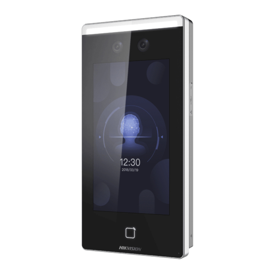
• Suggested height for face recognition: between 1.4 m and 1.9 • Deep learning algorithm • 50,000 face capacity, 5,000 fingerprint capacity, and 50,000 event capacity • Multiple authentication modes • Face recognition duration ≤ 0.5 s/User; face recognition accuracy rate ≥ 99% •... - Page 19 Table 2-1 Description of Face Recognition Terminal Name Description For fingerprint recognition. Fingerprint Note Module Only parts of models support fingerprint recognition function. Card Swiping Swipe card within this Area area. Display Screen 7-inch LCD touch screen. IR light camera for recording or capturing Camera (IR Light) videos or pictures in IR...
-
Page 20: Installation
3 Installation 3.1 Installation Environment • If installing the device indoors, the device should be at least 2 meters away from the light, and at least 3 meters away from the window or the door. • If installing the device outdoors, you should apply Sililcone sealant among the cable wiring area to keep the raindrop from entering. - Page 21 3. Use two supplied screws (4_KA4 × 22-SUS) to secure the mounting plate on the gang box. 4. Use another four supplied screws to secure the mounting plate on the wall. Figure 3-2 Install Mounting Plate 5. Remove the two screws on the rear panel and remove the sheet to display the wiring terminals.
-
Page 22: Install Without Gang Box
Figure 3-5 Install Device 11. Use two supplied screws (SC-M4 × 12TP10-SUS) to secure the device and the mounting plate. Figure 3-6 Secure Device Note • The installation height here is the recommended height. You can change it according to your actual needs. •... - Page 23 Figure 3-7 Mounting Template 2. Drill 6 holes on the wall or other surface according to Hole 1 and Hole 2 in the mounting template. 3. Insert the screw sockets of the setscrews in the drilled holes. Figure 3-8 Insert Screw Socket 4.
- Page 24 Figure 3-9 Install Mounting Plate 5. Remove the two screws on the rear panel and remove the sheet to display the wiring terminals. 6. Route the cable through the cable hole of the mounting plate, and connect to corresponding external devices' cables. 7.
-
Page 25: Wiring
Figure 3-12 Install Device 11. Use two supplied screws (SC-M4 × 12TP10-SUS) to secure the device and the mounting plate. Figure 3-13 Secure Device Note • The installation height here is the recommended height. You can change it according to your actual needs. •... -
Page 26: Terminal Description
Note • If cable size is 18 AWG, you should use a 12 V power supply. And the distance between the power supply and the device should be no more than 20 m. • If the cable size is 15 AWG, you should use a 12 V power supply. - Page 27 Functio Descri Group Color Name ption Yellow/ Alarm Orange Input 2 Yellow/ Purple Alarm Alarm Yellow/ Output Output Brown Wiring Yellow/ Yellow 485+ RS-485 Wiring RS-485 Blue 485- Black Ground Wiegan Green Wiring Wiegan White Wiring Wiegan Group Brown Authent Wiegan icated Wiegan...
-
Page 28: Wire Device
Functio Descri Group Color Name ption Lock White/ Wiring (NO) Door Yellow/ SENSO Contac Green Exit Yellow/ Door Gray Wiring 4.2 Wire Device You can connect the terminal with peripherals. The wiring diagram without secure door control unit is as follows. Figure 4-2 Device Wiring Note •... -
Page 29: Activation
Figure 4-3 Secure Door Control Unit Wiring Note The secure door control unit should connect to an external power supply separately. The suggested external power supply is 12V, 0.5A. 5 Activation You should activate the device before the first login. After powering on the device, the system will switch to Device Activation page. -
Page 30: Activate Via Sadp
Before You Start • Get the SADP software from the supplied disk or the official website http://www.hikvision.com/en/ , and install the SADP according to the prompts. • The device and the PC that runs the SADP tool should be within the same subnet. -
Page 31: Basic Operation
For some devices, you are required to create the password to activate them before they can be added to the software and work properly. Steps Note This function should be supported by the device. 1. Enter the Device Management page. 2. -
Page 32: Set Recognition Mode
Figure 6-1 Welcome Page 2. Tap OK to save. Note • You can also change the settings in System Settings. • If you install the device indoors near the window or the face recognition function is not working well, select Others. •... -
Page 33: Login
Figure 6-2 Welcome Page 2. Tap OK to save. Note • If you do not configure the recognition mode and tap OK, the system will select Normal by default. • If you activate the device via other tools remotely, the system will select Normal as the recognition mode by default. -
Page 34: Login By Administrator
Figure 6-3 Home Page 6.3.2 Login by Administrator After you add the administrator for the device, only the administrator can login the device for device operation. Steps 1. Long tap on the initial page for 3 s to enter the admin login page. -
Page 35: Communication Settings
Figure 6-5 Home Page Note The device will be locked for 30 minutes after 5 failed fingerprint or card attempts. 3. Optional: Tap the lock icon and you can enter the device activation password for login. 4. Optional: Tap the exit button and you can exit the admin login page. -
Page 36: Set Wi-Fi Parameters
Note The device's IP address and the computer IP address should be in the same IP segment. 5. Tap to save the network parameters. 6.4.2 Set Wi-Fi Parameters You can enable the Wi-Fi function and set the Wi-Fi related parameters. Steps 1. -
Page 37: Set Wiegand Parameters
Note • Controller represents the access controller, Unit represents the secure door control unit and Reader represents the card reader. • Set the RS-485 address as 2 if you need to connect an access controller or card reader. 4. Tap to save the network parameters. -
Page 38: Add Face Picture
Note • The employee ID should be less than 32 characters. And it can be a combination of lower letters, upper letters, and numbers. • The employee ID should not start with 0 and should not be duplicated. 3. Tap the Name field and input the user name on the soft keyboard. - Page 39 Note • The employee ID should be less than 32 characters. And it can be a combination of lower letters, upper letters, and numbers. • The employee ID should not start with 0 and should not be duplicated. 3. Tap the Name field and input the user name on the soft keyboard.
-
Page 40: Add Fingerprint
8. Enable or disable the Administrator Permission function. Enable Administrator Permission The user is the administrator. Except for the normal attendance function, the user can also enter the Home page to operate after authenticating the permission. Disable Administrator Permission The User is the normal user. The user can only authenticate or take attendance on the initial page. -
Page 41: Add Card
For details about the instructions of scanning fingerprints, see Tips for Scanning Fingerprint. 8. Enable or disable the Administrator Permission function. Enable Administrator Permission The user is the administrator. Except for the normal attendance function, the user can also enter the Home page to operate after authenticating the permission. -
Page 42: Add Password
7. Enable or disable the Administrator Permission function. Enable Administrator Permission The user is the administrator. Except for the normal attendance function, the user can also enter the Home page to operate after authenticating the permission. Disable Administrator Permission The User is the normal user. The user can only authenticate or take attendance on the initial page. -
Page 43: Set Authentication Mode
6.5.6 Set Authentication Mode After adding the user's fingerprint, face picture, password, or other credentials, you should set the authentication mode and the user can authenticate his/her identity via the configured authentication mode. Steps 1. On the Add User or Edit User page, tap Authentication Mode to enter the Authentication Mode page. -
Page 44: Import Data
Figure 6-10 Transfer Page 2. On the Transfer page, tap Export Att. Data, Export User Data, Export Face Pic., Export Access Control Param., or Export Captured Pic. 3. Tap Yes on the pop-up page and the data will be exported from the device to the USB flash drive. -
Page 45: Identity Authentication
another files, named enroll_pic1, enroll_pic2, enroll_pic3, enroll_pic4, under the root directory. • Under the deep mode (face recognition mode), the imported pictures should be exported pictures of another device. • The employee ID should be less than 32 characters. It can be a combination of lower letters, upper letters, and numbers. -
Page 46: Authenticate Via 1:N Matching
Note • For better face authentication, the user height should between 140 cm and 190 cm and the distance between the user and the device should be between 30 cm and 100 cm. • For detailed information about scanning fingerprint, see Tips for Scanning Fingerprint. -
Page 47: Set Face Picture Parameters
On the Home page, tap System (System Settings) to enter the System Settings page. Figure 6-11 Basic Parameters Table 6-1 Basic Parameters Parameter Description Community Set the device installed community No. Building No. Set the device installed building No. Unit No. Set the device installed Unit No. - Page 48 Figure 6-12 Face Picture Parameters Table 6-2 Face Picture Parameters Parameter Description Set the matching threshold when authenticating via 1:N matching mode. 1:N Security The larger the value, the smaller the Level false accept rate and the larger the false rejection rate.
- Page 49 Parameter Description After enabling Live Face Detection Liveness function, you can set the matching Security security level when performing live face Level authentication. The distance from the face left side to the left margin in the recognition area. The actual distance should be larger than Margin the configured value when starting face (Left)
-
Page 50: Set Fingerprint Parameters
Parameter Description Note When there are both very bright and very dark areas simultaneously in the view, WDR balances the brightness level of the whole image and provide clear images with details. After enabling the ECO mode, the device can authenticate faces in the low light or dark environment. -
Page 51: Set Time
You can set the fingerprint security level in this section. Note Some device models do not support the fingerprint related functions. Figure 6-13 Fingerprint Parameters Security Level You can select the fingerprint security level. The higher is the security level, the lower is the false acceptance rate (FAR). -
Page 52: Set Manual Attendance
Tap T&A Status to enter the T&A Status page. Figure 6-15 Disable Attendance Mode Set the Attendance Mode as Disable. You will not view or configure the attendance status on the initial page. And the system will follow the attendance rule that configured on the platform. -
Page 53: Set Manual And Auto Attendance
Figure 6-17 Auto Attendance Mode 3. Select an attendance status and set its schedule. Note The attendance status will be valid within the configured schedule. For example, if set the Break Out Schedule as Monday 11:00, and Break In Schedule as Monday 12:00, the valid user's authentication from Monday 11:00 to 12:00 will be marked as break. -
Page 54: Set Access Control Parameters
Result On the initial page and authenticate. If you do not select a status, the authentication will be marked as the configured attendance status according to the schedule. If you tap Select Status and select a status to take attendance, the authentication will be marked as the selected attendance status. -
Page 55: Maintenance
Parameter Description Enable the function and you cannot NFC Anti- C loning use the cloned card for authentication. You can select "Open (Remain Open)" or "Close (Remian Closed)" Door Contact according to your actual needs. By default, it is Close (Remian Closed). When enabling the anti-... -
Page 56: Data Management
Figure 6-20 Upgrade 6.11.2 Data Management On the Data Management page, you can delete all events, delete user data, delete all data, delete captured pictures, restore to factory settings, or restore to default settings. Tap Data (Data Management) to enter the Data Management page. -
Page 57: View System Information
Figure 6-21 Log Query 2. Tap Card on the left of the page and select a search type from the drop-down list. 3. Tap the input box and input the employee ID, the card No., or the user name for search. 4. -
Page 58: Two-Way Audio
View Device Information You can view the device information. Tap Info. (System Information) → Device to enter the Device page. Note Some device models do not support displaying the fingerprint information. Open Source License View the Open Source License information. Tap Info. -
Page 59: Call Device From Client Software
2. Run the client software and the control panel of the software pops up. 3. Click Device Management to enter the Device Management interface. 4. Add the master station and the device to the client software. Note For details about adding device, see Add Device. 5. -
Page 60: Client Software Configuration
4. Add the indoor station and the device to the client software. Note For details about adding device, see Add Device. 5. Link a user to an indoor station and set a room No. for the indoor station. 6. Tap on the authentication page of the device. - Page 61 Enter a descriptive name for the device. IP Address Enter the device's IP address. The IP address of the device is obtained automatically in this adding mode. Port You can customize the port number. The port number of the device is obtained automatically in this adding mode. User Name By default, the user name is admin.
- Page 62 Refresh Click on Operation column to get the latest device information. Delete Device Select one or multiple devices and click Delete to delete the selected device(s) from the client. Add Multiple Online Devices You can add multiple online devices to the client in a batch. Before You Start Make sure the to-be-added devices are online.
- Page 63 Remote Click on Operation column to set Configuration remote configuration of the corresponding device. Note See the user manual of the device for details. Device Status Click on Operation column to view device status, including cameras, recording status, signal status, hardware status, etc.
- Page 64 Enter the device user name. By default, the user name is admin. Password Enter the device password. Caution The password strength of the device can be automatically checked. We highly recommend you change the password of your own choosing (using a minimum of 8 characters, including at least three kinds of following categories: upper case letters, lower case letters, numbers, and special characters) in order to increase the security of your product.
- Page 65 Steps 1. Enter the Device Management module. 2. Optional: Click on the right of Device Management and select Device. The added devices are displayed in the list. 3. Click Add to open the Add window. 4. Select IP Segment as the adding mode. 5.
- Page 66 For areas where devices using dynamic IP addresses instead of static ones, you can add access control device connected via EHome protocol by specifying the EHome account. Before You Start Set the network center parameter first. For details, refer to Set Network Parameters.
-
Page 67: Reset Device Password
You can enter 0 or 1 which indicated different adding modes. 0 indicates that the device is added by IP address or domain name; 1 indicates that the device is added via EHome. Address Edit the address of the device. If you set 0 as the adding mode, you should enter the IP address or domain name of the device;... -
Page 68: Person Management
4. Click Export to save the device file on your PC and then send the file to our technical support. Note For the following operations for resetting the password, contact our technical support. Caution The password strength of the device can be automatically checked. -
Page 69: Configure Basic Information
Show Persons Check Show Persons in Sub Organization in Sub and select an organization to show Organization persons in its sub organizations. 7.2.2 Configure Basic Information You can add person to the client software one by one and configure the person's basic information such as name, gender, phone number, etc. -
Page 70: Upload A Face Photo From Local Pc
Note You need to click Settings to set the card issuing mode and related parameters first. For details, refer to Set Card Issuing Parameters. 5. Select the card type according to actual needs. Normal Card The card is used for opening doors for normal usage. Duress Card When the person is under duress, he/she can swipe the duress card to open the door. -
Page 71: Take A Photo Via Client
7. Confirm to add the person. - Click Add to add the person and close the Add Person window. - Click Add and New to add the person and continue to add other persons . 7.2.5 Take a Photo via Client When adding person, you can take a photo of the person by the webcam of the PC running the client and set this photo as the person's profile. -
Page 72: Collect Fingerprint Via Client
Note Enter the person's basic information first. For details about configuring person's basic information, refer to Configure Basic Information. 3. Click Add Face in the Basic Information panel. 4. Select Remote Collection. 5. Select an access control device which supports face recognition function from the drop-down list. -
Page 73: Collect Fingerprint Via Access Control Device
- Click Add to add the person and close the Add Person window. - Click Add and New to add the person and continue to add other persons. 7.2.8 Collect Fingerprint via Access Control Device When adding person, you can collect fingerprint information via the access control device's fingerprint module. -
Page 74: Customize Person Information
The PIN code must be used after card or fingerprint when accessing. It cannot be used independently. It should contain 4 to 8 digits. Super User If the person is set as a super user, he/she will have authorization to access all the doors/floors and will be exempted from remaining closed restrictions, all anti- passback rules, and first person authorization. -
Page 75: Configure Resident Information
3) Enter the property name. 4) Click OK. 3. Set the custom information when adding a person. 1) Select an organization in the organization list to add the person and click Add. Note Enter the person's basic information first. For details about configuring person's basic information, refer to Configure Basic Information. -
Page 76: Import And Export Person Identify Information
Note Enter the person's basic information first. For details about configuring person's basic information, refer to Configure Basic Information. 3. In the Additional Information panel, enter the additional information of the person, including person's ID type, ID No., job title, etc., according to actual needs. 4. -
Page 77: Export Person Information
Before You Start Be sure to have imported person information to the client beforehand. Steps 1. Enter the Person module. 2. Select an added organization in the list, or click Add in the upper-left corner to add an organization and then select it. 3. -
Page 78: Get Person Information From Access Control Device
Note All persons' face pictures will be exported if you do not select any organization. 3. Click Export to open the Export panel and check Face as the content to export. 4. Click Export to start exporting. Note • The exported file is in ZIP format. •... -
Page 79: Issue Cards To Persons In Batch
The persons under the organization will be displayed in the right panel. 3. Select the person to move. 4. Click Change Organization. 5. Select the organization to move persons to. 6. Click OK. 7.2.20 Issue Cards to Persons in Batch The client provides a convenient way to issue cards to multiple persons in a batch. -
Page 80: Configure Schedule And Template
The client provides two modes for reading a card's number: via card enrollment station or via the card reader of the access control device. If a card enrollment station is available, connect it to the PC running the client by USB interface or COM, and place the card on the card enrollment to read the card number. -
Page 81: Add Holiday
groups, so that the access group will take effect in the time durations of the template. Note For access group settings, refer to Set Access Group to Assign Access Authorization to Persons. 7.3.1 Add Holiday You can create holidays and set the days in the holidays, including start date, end date, and holiday duration in one day. - Page 82 Template includes week schedule and holiday. You can set week schedule and assign the time duration of access authorization for different person or group. You can also select the added holiday(s) for the template. Steps Note You can add up to 255 templates in the software system. 1.
-
Page 83: Set Access Group To Assign Access Authorization To Persons
2) Select a holiday in the left list and it will be added to the selected list on the right panel. 3) Optional: Click Add to add a new holiday. Note For details about adding a holiday, refer to Add Holiday. 4) Optional: Select a selected holiday in the right list and click to remove the selected one, or click Clear to clear all the selected holiday(s) in the right list. -
Page 84: Configure Advanced Functions
2) Click Apply All to Devices to start applying all the selected access group(s) to the access control device or door station. Caution • Be careful to click Apply All to Devices, since this operation will clear all the access groups of the selected devices and then apply the new access group, which may brings risk to the devices. - Page 85 Note • The displayed parameters may vary for different access control devices. • Some of the following parameters are not listed in the Basic Information page, click More to edit the parameters. Voice Prompt If you enable this function, the voice prompt is enabled in the device.
- Page 86 You can set the exit button as remaining closed or remaining open. Usually, it is remaining open. Door Locked Time After swiping the normal card and relay action, the timer for locking the door starts working. Extended Open Duration The door contact can be enabled with appropriate delay after person with extended accesss needs swipes her/his card.
- Page 87 2. In the device list on the left, click to expand the door, select a card reader and you can edit the card reader's parameters on the right. 3. Edit the card reader basic parameters in the Basic Information page. Note •...
- Page 88 View the number of existed fingerprints in the device. Fingerprint Recognition Level Select the fingerprint recognition level from the drop-down list. Face Recognition Timeout Value If the recognition time is more than the configured time, the device will remind you. Face 1:N Matching Threshold Set the matching threshold when authenticating via 1:N matching mode.
-
Page 89: Configure Remaining Open/Closed
Steps 1. Click Access Control → Advanced Function → Device Parameter to enter access control parameter configuration page. 2. In the device list on the left, click to expand the door, select an alarm input and you can edit the alarm input's parameters on the right. -
Page 90: Configure Multi-Factor Authentication
duration settings on this time bar to other week days. Delete Select one duration on the time bar, click Selected Delete Selected to delete this duration. Clear Click Clear to clear all the duration settings in the week schedule. 4. To set the door status during the holiday, click the Holiday and perform the following operations. - Page 91 1) Click Add on the right panel. 2) Create a name for the group as desired. 3) Specify the start time and end time of the effective period for the person/card group. 4) Select members(s) and card(s) in the Available list, and the selected member(s) and card(s) will be added to the Selected list.
-
Page 92: Configure Custom Wiegand Rule
Note You can check Offline Authentication to enable the super password authentication when the access control device is disconnected with the client. Local Authentication and Super Password Authentication by the access control device and by the super password. 4) Select the added person/card group in the left list below and it will be added to the Selected list on the right as the authentication group. -
Page 93: Configure Card Reader Authentication Mode And Schedule
3. Create a Wiegand name. Note Up to 32 characters are allowed in the custom Wiegand name. 4. Click Select Device to select the access control device for setting the custom wiegand. 5. Set the parity mode according to the property of the third party card reader. -
Page 94: Configure First Person In
Figure 7-3 Select Card Reader Authentication Mode Note PIN refers to the PIN code set to open the door. Refer to Configure Access Control Information. 2) Check the modes in the Available Mode list and they will be added to the selected modes list. 3) Click OK. -
Page 95: Configure Anti-Passback
Before You Start Set the access group and apply the access group to the access control device. For details, refer to Set Access Group to Assign Access Authorization to Persons. Perform this task when you want to configure opening door with first person. -
Page 96: Configure Other Parameters
Steps Note Either the anti-passing back or multi-door interlocking function can be configured for an access control device at the same time. For the configuration of multi-door interlocking, refer to . 1. Click Access Control → Advanced Function → Anti-Passback to enter the Anti-Passpack Settings page. - Page 97 A media access control address (MAC address) is a unique identifier assigned to the network interface for communications on the physical network segment. The maximum transmission unit (MTU) of the network interface. 6. Click Save. Set Network Parameters After adding the access control device, you can set the device log uploading mode, and create EHome account via wired network.
- Page 98 5. Select the Address Type as IP Address or Domain Name. 6. Enter IP address or domain name according to the address type. 7. Enter the port number for the protocol. Note The port number of the wireless network and wired network should be consistent with the port number of EHome.
- Page 99 In Status Monitoring module, you can capture a picture manually the access control device's camera by clicking a button. Before that, you need to set the parameters for the capture such as picture quality. Before You Start Before setting the capture parameters, you should set the saving path first to define where the captured pictures are saved.
- Page 100 After enabling the ECO mode, the device can authenticate faces in the low light or dark environment. And you can set he ECO mode threshold, ECO mode (1:N), and ECO mode (1:1). Note Only device in the normal mode supports configuring ECO mode parameters.
- Page 101 4. Set the switch to on to enable the M1 card encryption function. 5. Set the sector ID. The sector ID ranges from 1 to 100. 6. Click Save to save the settings. Set RS-485 Parameters You can set the access control device's RS-485 parameters including the baud rate, data bit, the stop bit, parity type, flow control type, communication mode, work mode, and connection mode.
- Page 102 Note If you set Communication Direction as Sending, you are required to set the Wiegand Mode as Wiegand 26 or Wiegand 6. Check Enable Wiegand to enable the Wiegand function. 7. Click Save. • The configured parameters will be applied to the device automatically.
- Page 103 Note By default, Attendance Status Required is enabled. 6. Set available time for the target attendance status. 1) Move the cursor on the target time and the enable checkbox will display. 2) Check the checkbox and set the available time. 3) Click anywhere on the page to confirm the settings.
- Page 104 Or when you authenticate on the device initial page, you will enter the Select Status page. Select a status to take attendance. Note If you do not select a status for about 20 s, the authentication will be failed and it will not be marked as a valid attendance. Set Manual and Auto Attendance Set the attendance mode as manual and auto and the device system will auto change the attendance status according to the...
-
Page 105: Configure Linkage Actions For Access Control
7.6 Configure Linkage Actions for Access Control You can configure different linkage actions for the event detected by the access control device. After that, linkage actions will be triggered once the event happens. This mechanism is used for notifying the security personnel the event, or triggering automatic access control in real time. -
Page 106: Configure Device Actions For Access Event
2) Click OK. 5. Enable the event so that when the event is detected, en event will be sent to the client and the linkage actions will be triggered. 6. Optional: Click Copy to... to copy the event settings to other access control device, alarm input, door, or card reader. -
Page 107: Configure Device Actions For Card Swiping
Note The target door and the source door cannot be the same one. Audio Play The audio prompt will be triggered. And the select audio index related audio content will be played according to the configured play mode. 7. Click Save. 8. -
Page 108: Configure Device Actions For Person Id
Note The device should support recording. Alarm Output The alarm output will be triggered for notification. Alarm Input Arm or disarm the alarm input. Note The device should support alarm input function. Access Point The door status of open, close, remain open, or remain closed will be triggered. -
Page 109: Door Control
Buzzer on Controller The audible warning of access control device will be triggered. Buzzer on Reader The audible warning of card reader will be triggered. Capture An event-related picture will be captured when the selected event happens. Recording An event-related picture will be captured when the selected event happens. -
Page 110: Control Door Status
control will not show. For setting the user permission, refer to Person Management. 7.7.1 Control Door Status You can control the status for a single door, including opening door, closing door, remaining the door open, and remaining the door closed. Steps 1. -
Page 111: Event Center
Steps 1. Click Monitoring and select a group from the drop-down list on the upper-right corner. The access records triggered at the doors in the selected group will display in real time. You can view the details of the records, including card No., person name, organization, event time, etc. - Page 112 Before You Start Enable receiving events from devices before the client can receive event information from the device, see Enable Receiving Event Notification from Devices for details. Steps 1. Click Event Center → Real-time Event to enter the real-time event page and you can view the real-time events received by the client.
-
Page 113: Search Historical Events
Clear Events Click Clear to clear the all the events in the event list. Send Email Select an event and then click Send Email, and the information details of this event will be sent by email. Note You should configure the email parameters first, see for details. - Page 114 All Records: You can filter the events from all the video • intercom events, and you need to set the following filter conditions: device, priority, status. Only Unlocking: You can filter the events from all the video • intercom unlocking events, and you need to set the following filter conditions: device, unlocking type.
-
Page 115: Time And Attendance
Remark to add more remarks for this handled event. Batch Handle Handle events in a batch: Select the events Events which need to be processed, and then click Handle in Batch, and enter the processing suggestion. Note After an event is handled, the Handle button will become Add Remark, click Add Remark to add more remarks for this handled event. - Page 116 Steps Note The parameters configured here will be set as default for the newly added time period. It will not affect the existed one(s). 1. Enter Time & Attendance module. 2. Click Attendance Settings → General Rule . 3. Set the day as week beginning and the date as month beginning.
- Page 117 3. Optional: Set Set All Card Readers as Check Points switch to off. Only the card readers in the list will be set as the attendance check points. 4. Check the desired card reader(s) in the device list as attendance check point(s). 5.
- Page 118 5. Custom a name for the holiday. 6. Set the start date of the holiday. Example If you want to set the forth Thursday in November, 2019 as the Thanksgiving Day holiday, you should select 2019, November, 4th, and Thursday from the four drop-down lists. 7.
- Page 119 record from client software to the third-party database automatically. Steps 1. Enter Time & Attendance module. 2. Click Attendance Settings → Third-Party Database . 3. Set Apply to Database switch to on to enable synchronization function. 4. Set the required parameters of the third-party database, including database type, server IP address, database name, user name and password.
-
Page 120: Add Timetable
The break duration will be calculated and excluded from work hours according to actual check-in and check-out time. Note If you select Must Check as calculation method, you need to set attendance status for late or early returning from break. 5. - Page 121 Figure 7-7 Add Timetable 3. Create a name for the timetable. Note You can click the color icon beside the name to customize the color for the valid timetable on the time bar on the bottom of the page。 4. Select the timetable type. General Suitable for general attendance scene, which requires the fixed start-work time and end-work time, and you can set...
-
Page 122: Add Shift
Set the start-work time and end-work-time. Valid Check-in/out Time On the time bar, adjust the yellow bar to set the timetable during which the check-in or check-out is valid. Calculated as Set the duration calculated as the actual work duration. Late/Early Leave Allowable Set the timetable for late or early leave. -
Page 123: Manage Shift Schedule
Figure 7-8 Add Shift 6. Click Save. The added shift lists on the left panel of the page. At most 64 shifts can be added. 7. Optional: Assign the shift to organization or person for a quick shift schedule. 1) Click Assign. 2) Select Organization or Person tab and check the desired organization(s) or person(s) box. - Page 124 Note If Include Sub Organization is checked, when selecting the organization, its sub organizations are selected at the same time. 4. Select the shift from the drop-down list. 5. Check the checkbox to enable Multiple Shift Schedules. Note After checking Multiple Shift Schedules, you can select the effective time period(s) from the added time periods for the persons in the department.
- Page 125 It contains more than one timetables. The person can check in/out in any of the timetables and the attendance will be effective. If the multiple shift schedules contains three timetables: 00:00 to 07:00, 08:00 to 15:00 and 16:00 to 23:00. The attendance of the person adopting this multiple shift schedules will be effective in any of the three timetables.
-
Page 126: Manually Correct Check-In/Out Record
Set other rule for the schedule, such as Check-in Not Required, andCheck-out Not Required. 6. Click Save. Check Shift Schedule You can check the shift schedule in calendar or list mode. You ca also edit or delete the shift schedule. Steps 1. -
Page 127: Add Leave And Business Trip
Note In calendar mode, you need to click Calculate to get the attendance status of the person in one month. Edit • In calendar mode, click the related label on date to edit the details. • In list mode, double-click the related filed in Date, Handling Type, Time, or Remark column to edit the information. -
Page 128: Calculate Attendance Data
Edit • In calendar mode, click the related label on date to edit the details. • In list mode, double-click the filed in Date, Handling Type, Time, or Remark column to edit the related information. Delete Delete the selected items. Export Export the attendance handling details to local PC. -
Page 129: Attendance Statistics
Export Click Export to export attendance data to local PC. Note The exported details are saved in CSV format. 7.9.8 Attendance Statistics You can check the original attendance record, generate and export the attendance report based on the calculated attendance data. - Page 130 It supports to generate the a series of attendance reports manually to view the employees' attendance results. Before You Start Calculate the attendance data. Note You can calculate the attendance data manually, or set the schedule so that the client can calculate the data automatically every day.
-
Page 131: Remote Configuration (Web)
Example If you set the effective period as 2018/3/10 to 2018/4/10, select Friday as the sending date, and set the sending time as 20:00:00, the client will send the report at 8 p.m. on Fridays during 2018/3/10 to 2018/4/10. Note Make sure the attendance records are calculated before the sending time. -
Page 132: Set System Maintenance
2. Press CTRL and click to enter the remote configuration page. 3. Click System → Time to configure the time zone. 4. Optional: Check Enable NTP and set the NTP server address, the NTP port, and the synchronization interval. 5. Optional: Check Enable DST and set the DST start time, end time and the bias. -
Page 133: Configure Rs-485 Parameters
3) Click Upgrade to start upgrading. Note Do not power off during the upgrading. 7.10.5 Configure RS-485 Parameters You can set the RS-485 parameters including the baud rate, data bit, stop bit, parity type, communication mode, work mode, and connection mode. Steps 1. -
Page 134: Configure Network Parameters
The user information verification is compatible with the old client software version when logging in. Encryption Mode High security level during the user information verification when logging in. 6. Optional: Check Enable SSH. 7. Click Save. 7.10.8 Configure Network Parameters Steps 1. -
Page 135: Configure Face Picture Parameters
Note Only the access control device and other devices or systems (such as door station, indoor station, master station, platform) are in the same IP segment, the two-way audio can be performed. Click Maintenance and Management → Device to enter the device list. -
Page 136: Configure Supplement Light Parameters
The distance percentage from the face left side to the left margin in the recognition area. The actual distance percentage should be larger than the configured value when face picture authentication. Other percentages, distances, and angles should also meet their conditions. -
Page 137: Set Room No
7. Click Save to save the settings. 7.10.14 Set Room No. Set the device type, community No., building No., floor No., and unit No., and room No. Click Maintenance and Management → Device to enter the device list. Press CTRL and click to enter the remote configuration page. -
Page 138: Tips For Scanning Fingerprint
A. Tips for Scanning Fingerprint Recommended Finger Forefinger, middle finger or the third finger. Correct Scanning The figure displayed below is the correct way to scan your finger: You should press your finger on the scanner horizontally. The center of your scanned finger should align with the scanner center. -
Page 139: Tips When Collecting/Comparing Face Picture
B. Tips When Collecting/Comparing Face Picture The position when collecting or comparing face picture is as below: Positions (Recommended Distance: 0.5 m) Expression • Keep your expression naturally when collecting or comparing face pictures, just like the expression in the picture below. •... -
Page 140: Tips For Installation Environment
C. Tips for Installation Environment 1. Light Source Illumination Reference Value Candle: 10Lux Bulb: 100~850Lux Sunlight: More than 1200Lux 2. Install the device at least 2 meters away from the light, and at least 3 meters away from the window or door. 3.Avoid backlight, direct and indirect sunlight... -
Page 141: Relationship Between Wake-Up Distance And Environment
D. Relationship between Wake-up Distance and Environment Environmen Short Medium Long Normal 1.06 m 1.67 m 3.62 m White Wall Acrylic Wall At Dust 0.85/0.73 m 1.30/1.21 m 4.16 m (Low Laboratory Illumination Human 0.74 m 0.94 m 1.50/1.45 m Body Window Glass... -
Page 142: Dimension
E. Dimension Device with Fingerprint Module Figure E-1 Device with Fingerprint Module Device without Fingerprint Module Figure E-2 Device without Fingerprint Module...
Need help?
Do you have a question about the DS-K1T607 Series and is the answer not in the manual?
Questions and answers