Table of Contents
Advertisement
Quick Links
Advertisement
Table of Contents

Related Manuals for IFM ECOMAT 300 AL1000


Summary of Contents for IFM ECOMAT 300 AL1000
- Page 1 Device manual IO-Link master ProfiNet AL1000...
-
Page 2: Table Of Contents
IO-Link master Contents 1 Preliminary note � � � � � � � � � � � � � � � � � � � � � � � � � � � � � � � � � � � � � � � � � � � � � � � � � 5 2 Safety instructions �... - Page 3 IO-Link master 13 Technical data� � � � � � � � � � � � � � � � � � � � � � � � � � � � � � � � � � � � � � � � � � � � � � � � � 18 14 Connection options �...
- Page 4 34�2 Hardware � � � � � � � � � � � � � � � � � � � � � � � � � � � � � � � � � � � � � � � � � � � � � � � � 47 35 Integrate ifm ProfiNet device in the S7 controller (STEP 7) � � � � � � � � � � � � � � 47 35�1 Creating/opening a project �...
-
Page 5: Preliminary Note
IO-Link master 1 Preliminary note This document applies to devices of the type "IO-Link master" (art� no� AL1000)� This document is intended for specialists� These specialists are people who are qualified by their appropriate training and their experience to see risks and to avoid possible hazards that may be caused during operation or maintenance of the device�... -
Page 6: Safety Instructions
IO-Link master 2 Safety instructions These instructions contain texts and figures concerning the correct handling of the device and must be read before installation or use� Observe the operating instructions� Non-observance of the instructions, operation which is not in accordance with use as prescribed below, wrong installation or incorrect handling can seriously affect the safety of operators and machinery�... -
Page 7: Documentation
IO-Link master ► Devices that are designed for mounting in housings or control cabinets must only be operated and controlled after they have been installed with the housing closed� Desktop or portable units must only be operated and controlled in enclosed housings�... -
Page 8: Product Description
IO-Link master 5 Product description 5.1 DI (digital input) The digital inputs receive the digital control signals from the process level� These signals are transferred to the higher-level automation device via the network/bus� The signal status is indicated via LEDs� The sensors are connected via M12 screw connectors�... -
Page 9: Scale Drawings
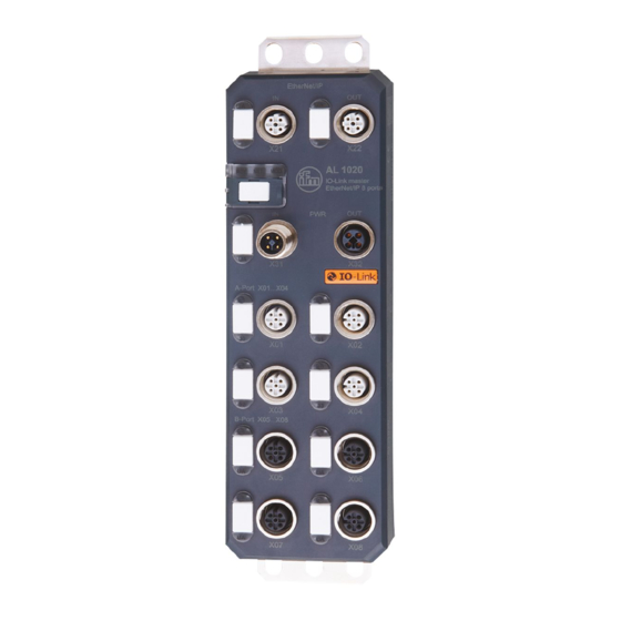
IO-Link master 7 Scale drawings 7.1 Dimensions of the screw holes in the fixing clips 8 Structure of the device 1� Fixing clips ( FE connection) 2� Network or bus connection (IN, OUT) 3� Connections for the supply voltages 4� Connections for inputs/outputs or IO-Link ports 5�... -
Page 10: 8�1 Diagnostic And Status Indicators
IO-Link master 8.1 Diagnostic and status indicators 8.1.1 Diagnostics The diagnostic indicators (green/yellow/red) indicate whether an error is present or not� In case of an error, they indicate the error type and location� The device is operating correctly if all green indicators are on� 8.1.2 Status The status indicators (yellow) indicate the signal state of the corresponding input/ output or of the IO-Link port�... -
Page 11: 9�1 Mechanical Strain
IO-Link master Data corruption and loss A minimum distance between the cabling and possible sources of interference (e�g�, machines, wel- ding equipment, power lines) is defined in the applicable regulations and standards� During system planning and installation, these regulations and standards must be taken into account and observed� Protect the bus cables from sources of electric/magnetic interference and mechanical strain�... -
Page 12: 9�5 Cable Routing Outside Buildings
– a metal pipe� 9.6.3 Surge protective devices ifm recommends wiring all the wires of the cable to surge protective devices in order to protect the devices against surge voltages� Observe all national and international regulations when installing surge protective devices�... -
Page 13: 9�7 Surge Protection Measures
3� Equipotential bonding line 9.7 Surge protection measures ifm recommends wiring relay coils or motor coils to an RC element in order to protect the devices against interference� Depending on the application, the delay time of the relay can be increased by approximately 1 ms�... -
Page 14: 9�9 Installation Instructions
IO-Link master 9.9 Installation instructions Electrostatic discharge The device contains components that can be damaged or destroyed by electrostatic discharge� When handling the device, observe the necessary safety precautions against electrostatic discharge (ESD) according to EN 61340-5-1 and IEC 61340-5-1� Damage to the electronics ►... - Page 15 IO-Link master ► Use standard M5 screws with toothed lock washer and self-locking nuts� ► Observe the maximum torque of the screws� Functional grounding ► Functional grounding is crucial for interference-free operation� Ground the device by means of the mounting screws of the fixing clips�...
-
Page 16: Scale Drawing
IO-Link master 10 Scale drawing 198,5 Scale drawing AL1000 11 Electrical connection For the devices, a distinction is made between two voltages: – U to supply the communications power and the sensors (always required), – U for supplying the actuators, only required for devices with fixed outputs or for additional devices�... -
Page 17: 11�2 Power Supply U
IO-Link master ► Protect the power supplies independently� > This means that the bus can continue running even if some I/O devices are switched off� 11.2 Power supply U ► Connect power supply Usfor the logic and sensors to socket X31� ►... -
Page 18: 12�3 General Features
IO-Link master – 4 type A ports with an additional digital input – 4 type B ports with an additional voltage supply ● Connection of IO-Link ports using M12 connectors (A-coded, 5 poles) ● Parameter data storage on the master ●... - Page 19 IO-Link master Conformance class Update rate [ms] Number of supported application relationships (AR) Additional protocols SNMP v1, HTTP, TFTP, FTP ProfiNet protocols LLDP, MRP client, DCP, DCE-RPC Supply of the module electronics and sensors Connection method M12 connector (T-coded) Number of poles Designation Supply voltage [V] 24 DC...
- Page 20 IO-Link master Sensor current [mA] max� 200 for each channel from L+/L- Total current consumption [mA] max� 1�6 from L+/L- Input voltage range "0" signal [V] -3���5 DC Input voltage range "1" signal [V] 15���30 DC Input filter time [µs] <...
- Page 21 Transient surge voltage (surge) EN 61000-4-5/IEC 61000-4-5 criterion B; DC supply lines: ±0�5 kV / ±0�5 kV (symmetrical/ asymmetrical) Conducted interference EN 61000-4-6/IEC 61000-4-6 criterion A; test voltage 10 V Noise emission test to EN 61000-6-4 Radio interference properties EN 55022 class A Approvals see www�ifm�com...
-
Page 22: Connection Options
IO-Link master 14 Connection options 14.1 ProfiNet and voltage supply connection Port 1 (X21): Ethernet port 1 Port 2 (X22): Ethernet port 2 IN (X31): voltage supply IN (logic and sensors) Port1 Port2 IN (X31): voltage supply IN (IO-Link actuators) U OUT U IN OUT (X32): voltage supply OUT for additional devices... -
Page 23: 14�4 Connection Of Io Link Ports And Digital Inputs
IO-Link master 14.4 Connection of IO Link ports and digital inputs IO-Link 1���8 (X01���X08): IO-Link ports 1���8 DI1���DI4 (X01���X04): inputs 1���4 DI 1...4 IOL1...8 14.5 Pin connection of the inputs and IO-Link ports IO-Link-A ports (X01���X04) IO-Link B ports (X05���X08) 1: 24 V DC (L+) 1: 24 V DC (L+) 2: DI... -
Page 24: Local Status And Diagnostic Indicators
IO-Link master Implement the FE connection using mounting screws in order to ensure immunity to interference� To ensure IP65 / IP67 protection, cover unused sockets with protective caps� Only supply the IO-Link master and the IO-Link devices with the voltage U und U provided at the terminal points�... - Page 25 IO-Link master Designation Colour Meaning State Description Green/ yel- Ready Green ON Device is ready for operation low / red Yellow Firmware update is being performed flashing Green / yel- Overvoltage or undervoltage at U low flashing Temperature of the device is in the critical area Failure of the actuator supply U and red U...
-
Page 26: 15�2 Indicators For The Io-Link Ports And Inputs
IO-Link master 15.2 Indicators for the IO-Link ports and inputs DI 1...4 IOL1...8 Designation Colour Meaning State Description IO-Link LED Green/ Status of Green ON In IO-Link mode yellow/ red the IO-Link IO-Link communication present ports Green In IO-Link mode (X01���X08) flashing IO-Link communication... -
Page 27: Profinet Data Model
IO-Link master Designation Colour Meaning State Description Green/red Actuator Green ON Actuator voltage present supply for Green, OFF Actuator voltage not present X05 ��� X08 Red ON Short circuit between pin 2 and pin 5 The numbering of the LEDs is as follows: The first position specifies the byte, the second position specifies the bit�... - Page 28 IO-Link master Byte 0 (COM control) can be used to temporarily (as long as the corresponding COM control bit is set) switch one or more IO-Link ports previously configured in the digital input mode (DI) to the IO-Link mode� Cyclic and acyclic communication can therefore be established with the connected IO-Link device�...
- Page 29 IO-Link master Parameter Possible values Description Substitute values for DO 0 = zero (def) Specification of a substitute value sample for the IO-Link ports in the Possible values: DO mode (pin 4)� 0 … 255dec In order to use this parameter, the value "Substitute values"...
-
Page 30: 16�2 Flexible Module Configuration
IO-Link master 16.2 Flexible module configuration Up to eight further modules can be flexibly configured in slots 1�2 to 1�9, each of these represents a physical IO-Link port� The basic mode of the IO-Link port and the process data length are determined with the selection of the module� Operating mode and process data of the IO-Link port The possible submodules are shown below�... - Page 31 IO-Link master Submodule Process data length in bytes Description/start-up parameters Input Output IOL_I_nByte 1���32 1���32 Port mode (operating mode): IO-Link (+DevPrm*) ��� Device check (identification level): IOL_O_nByte – Vendor ID (2 bytes) – Device ID (3 bytes) (+DevPrm*) … Data storage: IOL_I/O_n/nByte 0 = deactivated (+DevPrm*)
- Page 32 IO-Link master Parameter Possible values Description Vendor ID 0000 ��� FFFF Vendor ID, identification level 1 The vendor ID of the connected IO-Link device for the respective port can be parameterised via the level� The vendor ID can be found in the data sheet of the IO-Link device�...
-
Page 33: M Functions
IO-Link master Data storage Deactivated and deleted The data storage mechanism is deactivated and the master deletes all stored parameters for the respective port� The data storage mechanism is supported from IO-Link specification v1�1� Both the IO-Link master and the device must support at least IO-Link v1�1�... - Page 34 IO-Link master I&M 1 (slot 0) I&M data Access / data type Presets TAG_FUNCTION Read/write / 32 bytes "20 " (empty) TAG_LOCATION Read/write / 22 bytes "20 " (empty) I&M 2 (slot 0) I&M data Access / data type Presets INSTALLATION_DATE Read/write / 16 bytes "20...
- Page 35 IO-Link master I&M 16 ��� 23 (slot 1, subslot 1): IO-Link device directory For each IO-Link, an individual Identification & Maintenance function is available in the area of I&M 16 (index B000 ) to I&M 23 (index B007 )� For I&M functions 16 to 23, the structure is made up of the following parameters: I&M data Access / data type...
-
Page 36: Set-Up
IO-Link master Access is only with read permission and exclusively via slot 1 and subslot 1 (status/control module)� 18 Set-up 18.1 On delivery/default settings On delivery, the following functions and features are available: IP settings ● ProfiNet name: no name assigned ●... -
Page 37: Parameterisation
Make sure you use the latest version of the FDCML / GSDML file and the latest documentation for the device� The latest files and documentation can be found on our web site at www�ifm�com� 20 LLDP - Link Layer Discovery Protocol The device supports LLDP to IEEE 802�1AB and therefore enables topology... -
Page 38: Snmp - Simple Network Management Protocol
IO-Link master 22 SNMP - Simple Network Management Protocol The device supports SNMP v1� For the object descriptions, please refer to the ASN1 descriptions of this product� The password for read access is "public" and cannot be changed� On delivery, the password for write/read access is "private" and can be changed at any time�... -
Page 39: Firmware Update
IO-Link master If you cannot access the WBM pages, check the connection settings in your browser and deactivate the proxy set� 27 Firmware update In order to update the firmware of the device, the device must be provided with a firmware container via a TFTP server or it must be loaded into the device via FTP�... -
Page 40: Substitute Value Behaviour
IO-Link master 30 Substitute value behaviour If PROFINET communication fails, all device outputs are set to the parameterised substitute values� Please refer to the "Status/control module -> Start-up parameters" and "Flexible module configuration -> Start-up parameters" chapters for the precise parameterisation of substitute values�... - Page 41 IO-Link master If the login is successful you will see the following window in the Windows Explorer: You see the following structure: If you do not enter any login details or wrong details, you get a message� Please check your login details and try again�...
-
Page 42: 32�2 Upload
IO-Link master 32.2 Upload ► Open the [Volume] folder and copy the firmware file to the root of the [Volume] folder�... -
Page 43: 32�3 Firmware Update
IO-Link master 32.3 Firmware update 32.4 Access the web server ► Open the web browser� ► Enter the IP address of the device in the address line of the web browser� Figure 4 shows the IP address in the address line of the Internet Explorer� This takes you to the homepage of the respective device�... -
Page 44: 32�5 Setting The Firmware Update Via Ftp
IO-Link master 32.5 Setting the firmware update via FTP Navigate to [Administration] (1) and then to the [Firmware Update] (2) page� ► In the next step select the setting FTP in the drop down menu�... -
Page 45: 32�6 Perform The Firmware Update
IO-Link master 32.6 Perform the firmware update To perform the firmware update, select the checkbox [Firmware Update on Next Reboot]� > The device then automatically updates the firmware upon the next reboot� If you want to start the device immediately, also select the checkbox [Reboot system after sending data]�... -
Page 46: 32�7 Read Out The Firmware Revision
IO-Link master Now you will need to authenticate: ► Enter your login details� ► Click on [OK]� ► Please wait a certain period of time and then refresh the web page or click on the picture of the product to reach the homepage� 32.7 Read out the firmware revision ►... -
Page 47: Setup As Per Step 7
Hardware requirements for the Siemens SIMATIC software: Please refer to the S7 documentation for the hardware requirements� 35 Integrate ifm ProfiNet device in the S7 controller (STEP 7) To integrate the device into the network, proceed as described in the manufacturer's documentation for your controller�... -
Page 48: 35�2 Install The Gsdml File
IO-Link master 35.2 Install the GSDML file Make sure you use the latest GSDML file� It is available on the Internet at www�ifm� com� Make sure that the name of the downloaded GSDML file is the same as the name displayed in the Download area�... - Page 49 IO-Link master The device now appears in the hardware catalogue under PROFINET IO → [Additional Field Devices] → [I/O] → [ifm electronic] →[field modules]�...
-
Page 50: 35�3 Inserting I/O Devices In The Hardware Configurator
IO-Link master 35.3 Inserting I/O devices in the hardware configurator ► Select the Profinet device in the hardware catalogue and move it to the Profinet network using drag & drop� The devices all have modules with the same structure in slot zero� This is where the communication submodules are located�... -
Page 51: 35�5 Assigning Device Names
IO-Link master The figure below shows an example configuration for the AL1000 device: 35.5 Assigning device names Profinet uses names to address the devices� Make sure that the device name only occurs once in the Profinet system� ► Observe the naming conventions listed below when assigning the device name� Naming conventions ●... - Page 52 IO-Link master First, the device is assigned a name in the configuration� ► Right-click on the device and select [Object Properties]� ► In the dialogue box that appears, enter a name for the device under [Device name]� In the figure below [AL1000] is used�...
- Page 53 IO-Link master ► Next, assign the same name to the device that was used in the hardware configuration� To do so, the device should be connected� The following steps must be carried out: ► In [HW Config], select the [Target system, Ethernet, Assign device name] menu�...
-
Page 54: 35�6 Fast Startup
IO-Link master 35.6 Fast startup In order to use the [Fast startup] function, prioritised startup must be activated in the Profinet IO device interface submodule (PN-IO)� The following steps must be carried out: Right-click on [PN-IO], then select [Object Properties]. >... - Page 55 IO-Link master Furthermore, both ports should be set to fixed values� This saves time for startup that would otherwise be needed to arrange the port configuration� The following steps must be carried out both for the device and the controller: Right-click on the ports, then select [Object Properties].
-
Page 56: 35�7 Media Redundancy Protocol
IO-Link master 35.7 Media Redundancy Protocol In order to configure the Media Redundancy Protocol (MRP), the ring must be set for the corresponding dialogue boxes of the Profinet interfaces� The following steps must be carried out Right-click on [Profinet IO Interface (PN-IO)], then select [Object Properties]� ►... - Page 57 IO-Link master In order to ensure that the watchdog is not triggered during the MRP failure detection time, it must be set to a larger value than the expected MRP failure detection time� The following steps must be carried out: Right-click on [Profinet IO Interface (PN-IO)], then select [Object Properties]�...
-
Page 58: 35�8 Identification And Maintenance
IO-Link master 35.8 Identification and maintenance The identification and maintenance (I&M) data records are split over several STEP 7 dialogue boxes� An online connection to the device is required to display the I&M data records� The following steps must be carried out: Switch the hardware manager to online view�... - Page 59 IO-Link master...
-
Page 60: 35�9 Diagnostic Alarms
IO-Link master 35.9 Diagnostic alarms The devices support the following diagnostic alarms Alarm code Module Alarm text Description 0x0002 Undervoltage Undervoltage U 0x0003 Overvoltage Overvoltage U 0x0004 Overload Overload U 0x0005 Overtemperature Excess temperature 0x0100 Actuator undervoltage Undervoltage U 0x0101 Actuator overvoltage Overvoltage U 0x0102... - Page 61 IO-Link master...
Need help?
Do you have a question about the ECOMAT 300 AL1000 and is the answer not in the manual?
Questions and answers