
Related Manuals for Rockwell Automation Allen-Bradley 440R-GL2S2T


Summary of Contents for Rockwell Automation Allen-Bradley 440R-GL2S2T
- Page 1 User Manual Original Instructions Guard Locking with Time-Delay (GLT) Safety Relay Catalog Number 440R-GL2S2T...
- Page 2 If this equipment is used in a manner not specified by the manufacturer, the protection provided by the equipment may be impaired. In no event will Rockwell Automation, Inc. be responsible or liable for indirect or consequential damages resulting from the use or application of this equipment.
-
Page 3: Table Of Contents
SWS Connections ......... 22 Rockwell Automation Publication 440R-UM010C-EN-P - September 2016... - Page 4 Index ............43 Rockwell Automation Publication 440R-UM010C-EN-P - September 2016...
-
Page 5: Summary Of Changes
A glossary of industrial automation terms and abbreviations. You can view or download publications at http://www.rockwellautomation.com/literature/. To order paper copies of technical documentation, contact your local Allen-Bradley distributor or Rockwell Automation sales representative. Rockwell Automation Publication 440R-UM010C-EN-P - September 2016... -
Page 6: Definitions
The Industrial Automation Glossary (publication AG-7.1) contains a glossary of terms and abbreviations that are used by Rockwell Automation to describe industrial automation systems. The following list of specific terms and abbreviations that are used in this manual: • N.C. (Normally Closed) – An electrical contact whose normal state (that is, no pressure or electrical potential applied) is in the closed position. -
Page 7: Hardware Features
To request access through the safety gate, the operator presses the Unlock Request button. The GLT safety relay initiates a stop and unlocks the safety gate after the time expires. Rockwell Automation Publication 440R-UM010C-EN-P - September 2016... -
Page 8: Function 2 - E-Stop
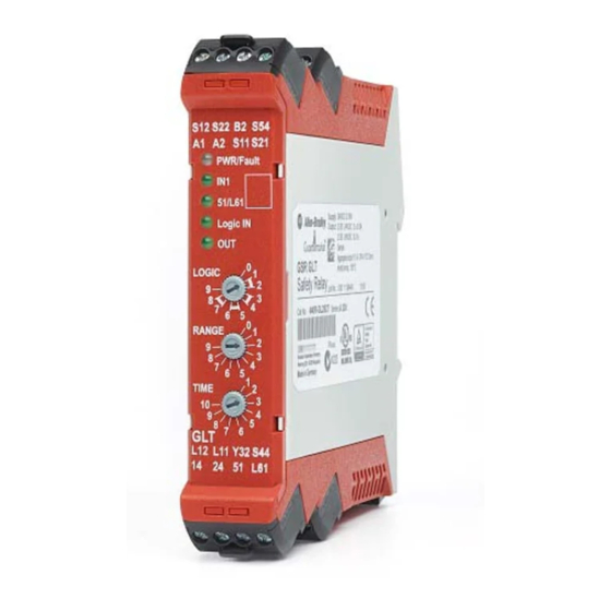
Figure 2 shows some of the key hardware features of the GLT safety relay. Figure 2 - GLT Hardware Details 8 Removable Terminals 5 Status Indicators 3 Multi-position Rotary Configuration Switches 8 Removable Terminals Rockwell Automation Publication 440R-UM010C-EN-P - September 2016... -
Page 9: Mounting Dimensions
2. Slide down until the housing catches the rail. 3. Swing the bottom down and give a little push until the latch clips onto the rail. Figure 4 - DIN Rail Mounting DIN Rail DIN Latch Rockwell Automation Publication 440R-UM010C-EN-P - September 2016... -
Page 10: Removable Terminals
Group 1, Class A industrial equipment according to IEC/CISPR 11. Without appropriate precautions, there may be difficulties with electromagnetic compatibility in residential and other environments due to conducted and radiated disturbances. Rockwell Automation Publication 440R-UM010C-EN-P - September 2016... -
Page 11: Prevent Excessive Heat
Harmful contaminants or dirt could cause improper operation or damage to components. In extreme cases, you may need to use air conditioning to help protect against heat buildup within the enclosure. Rockwell Automation Publication 440R-UM010C-EN-P - September 2016... - Page 12 Chapter 2 Installation Notes: Rockwell Automation Publication 440R-UM010C-EN-P - September 2016...
-
Page 13: Wiring Requirements And Recommendation
Wire Size Each terminal can accommodate copper wire with size from 0.2…2.5 mm (24…14 AWG). Use copper that withstands 60/75 °C. Terminal Torque Terminals must be torqued to 0.4 N•m (4 lb•in). Rockwell Automation Publication 440R-UM010C-EN-P - September 2016... -
Page 14: Terminal Assignments
Immediate Safety Output Channel 2 - Logic Setting 1, 2, 5, 6, 7, 8 Delayed Safety Output Channel 2 – Logic Setting 3, 4 Grounding the Controller There are no special grounding requirements. Terminal A2 must be connected to the common of a 24V supply. Rockwell Automation Publication 440R-UM010C-EN-P - September 2016... -
Page 15: Connecting A Power Supply
To comply with the CE Low Voltage Directive (LVD), power for the GLT safety relay must come from a DC source compliant with safety extra low voltage (SELV) or protected extra low voltage (PELV). The following Rockwell Automation Bulletin 1606 power supply catalog numbers are SELV- and PELV-compliant. • 1606-XLP30E •... -
Page 16: Safety Devices
When only one dual-channel E-stop button is used, the maximum safety performance rating is Cat 4 PLe and SIL CL3. Figure 10 - Connecting Mechanical Contacts of a TLS3-GD2 Interlock Switch Safety Gate 11 21 12 22 S12 S22 TLS3-GD2 Rockwell Automation Publication 440R-UM010C-EN-P - September 2016... -
Page 17: Safety Devices With Ossd Outputs
TIP OSSD1 can be connected to either S12 or S22 and OSSD2 can be connected to either S12 or S22. When using the TLS-ZR and 440G-LZ guard locking switches, the maximum safety performance rating is Cat 4 PLe and SIL CL3. Rockwell Automation Publication 440R-UM010C-EN-P - September 2016... -
Page 18: Unlock Request Input
The lock and reset request is connected to Terminal S44. Figure 13 - Lock Request Wiring Momentary PLC Output Normally-Open Push Button Processor 1756-OB16 1769-OB8 1746-OB4 Contactor 1734-OB2 Monitoring 1793-OB4 24V DC Com Rockwell Automation Publication 440R-UM010C-EN-P - September 2016... -
Page 19: Lock And Unlock Signals
ON immediately WARNING: You must confirm that the reclosing or resetting of an interlocking safeguard or E-stop device does not initiate hazardous machine operation. Figure 15 - Retriggerable Input Wiring 24V DC Com Rockwell Automation Publication 440R-UM010C-EN-P - September 2016... -
Page 20: Outputs
51 and L61 or two separate safety control relays can be connected to 51 and L61. A diode suppressor should be connected in parallel across the coil. Figure 18 - Interposing Relay Connections +24V DC 24V DC Com Rockwell Automation Publication 440R-UM010C-EN-P - September 2016... -
Page 21: Use Surge Suppressors
• Terminal L12 (input) • Terminal L11 (output) These terminals can only be connected to other devices that support single wire safety. When the SWS input is ON, the Logic IN indicator turns ON. Rockwell Automation Publication 440R-UM010C-EN-P - September 2016... -
Page 22: Sws Function
SWS input from a GSR DI safety relay and SWS output connection to a GSR EM expansion in parallel with a GSR DIS relay. The safety relays must have a common power reference (24V common). Rockwell Automation Publication 440R-UM010C-EN-P - September 2016... - Page 23 1 ms pulse, followed 600 µs later by a 600 µs pulse. This waveform is repeated every 4 ms. When inactive, the SWS is 0V. Figure 21 - SWS Waveform Terminals L11 and L12 1.6 2.2 4 ms Rockwell Automation Publication 440R-UM010C-EN-P - September 2016...
- Page 24 Chapter 3 Power, Ground, and Wire Notes: Rockwell Automation Publication 440R-UM010C-EN-P - September 2016...
-
Page 25: Logic Switch Setting
ATTENTION: When the GLT safety relay is configured for settings 5 or 7 and an E-stop device is connected to IN1, there must be no connection to the Logic IN (terminal L12). E-stops must always be available and cannot be bypassed or muted with 'OR' logic. Rockwell Automation Publication 440R-UM010C-EN-P - September 2016... -
Page 26: Range Switch Setting
Figure 22 - Configuration Switch Adjustment Mechanical Stops Rotate Along Arrow IMPORTANT Adjust the switches gently and do not turn past the mechanical stops. Rockwell Automation Publication 440R-UM010C-EN-P - September 2016... -
Page 27: Configuration Process
4. Verify the settings The status indicators flash for 0.5 seconds to indicate the switch setting. The number of flashes is equal to the switch setting. The flashing repeats after a 2 second pause. Rockwell Automation Publication 440R-UM010C-EN-P - September 2016... - Page 28 High Side High Side TLS-ZR or 440G-LZ) or E-stop function 2 times Standard guard locking switch (for High Side Low Side example, TLS3-GD2) 3 times Next generation guard locking switch Logic Link Function Rockwell Automation Publication 440R-UM010C-EN-P - September 2016...
-
Page 29: Status Indicators During Powerup
Logic IN signal at L12 is active Logic IN signal at L12 is OFF L11 is active and 14/24 are ON Y32 is ON Outputs are OFF Blinking Waiting for reset signal or timing cycle has started Rockwell Automation Publication 440R-UM010C-EN-P - September 2016... -
Page 30: Status Indicators During Diagnostics
• Short circuit fault on terminal L11 to ground. • With OSSD guard locking or E-stop function… • Short circuit fault on terminal 51 to ground. Correct the fault and cycle power to the GLT safety relay. Rockwell Automation Publication 440R-UM010C-EN-P - September 2016... -
Page 31: Additional Diagnostics
EPROM fault Compare state fault Cross fault Wiring at B2 differs from EPROM Input is open when gate is locked Switch overflow S12 fault S22 fault Main transistor fault Overvoltage S44 or S54 fault Rockwell Automation Publication 440R-UM010C-EN-P - September 2016... - Page 32 Chapter 5 Diagnostic Status Indicators and Troubleshooting Notes: Rockwell Automation Publication 440R-UM010C-EN-P - September 2016...
-
Page 33: Pulse Testing For Inputs
GLT safety relay can only be used in applications up to PLd and SIL 2. The outputs have built in redundancy. A main transistor supplies power to individual transistors for each output terminal as shown in Figure Figure 25 - Output Transistor Arrangement Main Transistor Individual Transistors Rockwell Automation Publication 440R-UM010C-EN-P - September 2016... - Page 34 L61, not 24V common. The pattern is repeated every 2639 ms. Figure 29 - Output Pulse Test Pattern for High/Low Side Guard Locking Terminal 1132 1339 1545 2639 2793 3564 Approximate Time (ms) Rockwell Automation Publication 440R-UM010C-EN-P - September 2016...
-
Page 35: General
Polyamide PA 6.6 Terminal Protection IP20 Enclosure Protection IP40 (NEMA 1) Environmental Attribute 440R-GL2S2T Operating Temperature -5…+55 °C (23…131 °F) Relative Humidity Vibration 10…55 Hz, 0.35 mm Shock 10 g, 16 ms Pollution Level Rockwell Automation Publication 440R-UM010C-EN-P - September 2016... -
Page 36: Inputs In1
OFF Current, Max 2 mA ON Current at 24V DC, Max 11 mA ON Current at 26.4V DC, Max 11.1 mA Galvanic Isolation: I/O from Logic Overvoltage Protection Input Capacitance 10 nF Duration 0.5…3.0 s Rockwell Automation Publication 440R-UM010C-EN-P - September 2016... -
Page 37: Retrigger
Pulse Test Duration 700 µs ≤ Pulse Test Period 13000 ms (less than 15 s) Maximum Resistance for the Auto Detection of a Coil Maximum Resistance for the Auto Detection of an LL Device Rockwell Automation Publication 440R-UM010C-EN-P - September 2016... -
Page 38: Lock Unlock Signals
OFF Current, Max 2 mA ON Current at 24V DC, Max 11 mA ON Current at 26.4V DC, Max 11.1 mA Galvanic Isolation: I/O from Logic Overvoltage Protection Reverse Voltage Protection Input Capacitance 10 nF Rockwell Automation Publication 440R-UM010C-EN-P - September 2016... -
Page 39: Single Wire Safety Output Signal
Single Wire Safety Input, L12 48 ms 48 ms 49 ms 37 ms 35 ms 38 ms Safety Inputs (S12, S22) 68 ms 61 ms 70 ms 55 ms 51 ms 57 ms Rockwell Automation Publication 440R-UM010C-EN-P - September 2016... - Page 40 Appendix A Specifications Notes: Rockwell Automation Publication 440R-UM010C-EN-P - September 2016...
-
Page 41: Agency Certifications
The following two tables provide the data that must be used to represent the GLT when calculating the safety integrity level (SIL) or the Performance Level (PL). Rockwell Automation Publication 440R-UM010C-EN-P - September 2016... -
Page 42: Sil Rating
2004/108/EC on Electromagnetic Compatibility (EMC) and the following standards: • EN 61000-6-4: Generic Standards - Emission Standard for Industrial Environments • EN 61000-6-2: Generic Standards - Immunity for Industrial Environments This product is intended for use in an industrial environment. Rockwell Automation Publication 440R-UM010C-EN-P - September 2016... -
Page 43: Index
41 enclosure mechanical contacts consideration 10 safety devices 16 environmental mounting specifications 35 dimensions 9 E-stop DIN Rail 9 function 8 European Union directives compliance 41 excessive heat prevent 11 Rockwell Automation Publication 440R-UM010C-EN-P - September 2016... - Page 44 6 specifications 39 surge suppressors 21 retrigger specifications 37 retriggerable input 19 wire 13 recommendation 13 requirement 13 safety size 13 single wire 21 safety devices 16 mechanical contacts 16 OSSD outputs 17 Rockwell Automation Publication 440R-UM010C-EN-P - September 2016...
- Page 46 Rockwell Otomasyon Ticaret A.Ş., Kar Plaza İş Merkezi E Blok Kat:6 34752 İçerenköy, İstanbul, Tel: +90 (216) 5698400 Publication 440R-UM010C-EN-P - September 2016 Supersedes Publication 440R-UM010B-EN-P - December 2015 Copyright © 2016 Rockwell Automation, Inc. All rights reserved. Printed in the U.S.A.
Need help?
Do you have a question about the Allen-Bradley 440R-GL2S2T and is the answer not in the manual?
Questions and answers