
Related Manuals for Rockwell Automation Allen-Bradley GLT


Summary of Contents for Rockwell Automation Allen-Bradley GLT
- Page 1 User Manual — Original Instructions GLT - Guard Locking with Time-Delay Safety Relay Catalog Number 440R-GL2S2T...
-
Page 2: Important User Information
If this equipment is used in a manner not specified by the manufacturer, the protection provided by the equipment may be impaired. In no event will Rockwell Automation, Inc. be responsible or liable for indirect or consequential damages resulting from the use or application of this equipment. -
Page 3: Who Should Use This Manual
A glossary of industrial automation terms and abbreviations. You can view or download publications at http:/www.rockwellautomation.com/literature/. To order paper copies of technical documentation, contact your local Allen-Bradley distributor or Rockwell Automation sales representative. Rockwell Automation Publication 440R-UM010A-EN-P - May 2015... -
Page 4: Definitions
Publication AG-7.1 contains a glossary of terms and abbreviations that are used Definitions by Rockwell Automation to describe industrial automation systems. Below is a list of specific terms and abbreviations that are used in this manual. • N.C. (Normally Closed) – An electrical contact whose normal state (i.e., no pressure or electrical potential applied) is in the closed position. -
Page 5: Table Of Contents
Configuration Details ........25 Rockwell Automation Publication 440R-UM010A-EN-P - May 2015... - Page 6 EMC Directive ..........40 Rockwell Automation Publication 440R-UM010A-EN-P - May 2015...
-
Page 7: Hardware Features
To request access through the safety gate, the operator presses the Unlock Request button. The GLT initiates a stop and unlocks the safety gate after the time expires. Rockwell Automation Publication 440R-UM010A-EN-P - May 2015... -
Page 8: Function 2 - E-Stop
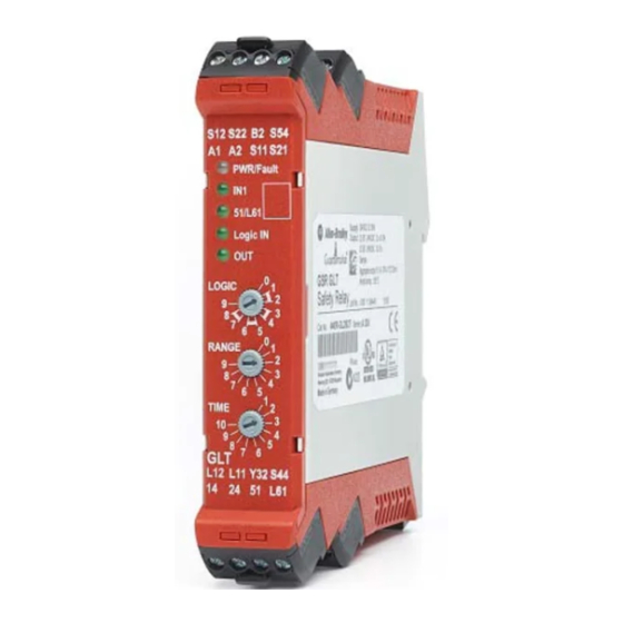
Figure 2 shows some of the key hardware features of the GLT. Figure 2 - GLT Hardware Details 8 Removable Terminals 5 Indicator LEDs 3 Multi-position Rotary Configuration Switches 8 Removable Terminals Rockwell Automation Publication 440R-UM010A-EN-P - May 2015... -
Page 9: Mounting Dimensions
2. Slide down until the housing catches the rail. 3. Swing the bottom down and give a little push until the latch clips onto the rail. Figure 4 - DIN Rail Mounting DIN Rail DIN Latch Rockwell Automation Publication 440R-UM010A-EN-P - May 2015... -
Page 10: Removable Terminals
This equipment is supplied as open-type equipment. It must be mounted within an enclosure that is suitably designed for those specific environmental conditions Rockwell Automation Publication 440R-UM010A-EN-P - May 2015... -
Page 11: Preventing Excessive Heat
Harmful contaminants or dirt could cause improper operation or damage to components. In extreme cases, you may need to use air conditioning to protect against heat buildup within the enclosure. Rockwell Automation Publication 440R-UM010A-EN-P - May 2015... - Page 12 Chapter 2 Installation Notes: Rockwell Automation Publication 440R-UM010A-EN-P - May 2015...
-
Page 13: Wiring Requirements And Recommendation
Each terminal can accommodate copper wire with size from 0.2 mm (24 AWG) to 2.5 mm (14 AWG). Use copper that withstands 60 / 75 °C. Terminal Torque Terminals should be torqued to 0.4 N•m (4 lb•in). Rockwell Automation Publication 440R-UM010A-EN-P - May 2015... -
Page 14: Terminal Assignments
Immediate Safety Output Channel 2 - Logic Setting 1, 2, 5, 6, 7, 8 Delayed Safety Output Channel 2 – Logic Setting 3, 4 There are no special grounding requirements. Terminal A2 must be connected to Grounding the Controller the common of a 24V supply. Rockwell Automation Publication 440R-UM010A-EN-P - May 2015... -
Page 15: Connecting A Power Supply
To comply with the CE Low Voltage Directive (LVD), the GLT must be powered by a DC source compliant with Safety Extra Low Voltage (SELV) or Protected Extra Low Voltage (PELV). The following Rockwell Automation Bulletin 1606 power supplies are SELV- and PELV-compliant. • 1606-XLP30E •... - Page 16 Regardless of how these are wired, performance remains the same. The GLT successfully recognizes when one or both channels open, and the GLT detects cross channel faults and single channel faults to +24V and to 24V common. Rockwell Automation Publication 440R-UM010A-EN-P - May 2015...
-
Page 17: Safety Devices With Ossd Outputs
Rockwell Automation PLC output modules are shown in Figure The unlock request is connected to Terminal S54. Figure 12 - Unlock Request Wiring Momentary PLC Output Normally-Open Push Button Processor 1756-OB16 1769-OB8 1746-OB4 1734-OB2 1793-OB4 24V DC Com Rockwell Automation Publication 440R-UM010A-EN-P - May 2015... -
Page 18: Lock And Reset Request Input
The retriggerable input only works with Logic Setting 5, 6, 7, and 8. Retriggerable operation is often used when long delay times are configured in the GLT. Rockwell Automation Publication 440R-UM010A-EN-P - May 2015... - Page 19 WARNING: The machine designer/user must confirm that the reclosing or resetting of an interlocking safeguard or E-stop device shall not initiate hazardous machine operation. Figure 15 - Retriggerable Input Wiring 24V DC Com Rockwell Automation Publication 440R-UM010A-EN-P - May 2015...
-
Page 20: Outputs
51 and L61 or two separate safety control relays can be connected to 51 and L61. A diode suppressor should be connected in parallel across the coil. Figure 18 - Interposing Relay Connections +24V DC 24V DC Com Rockwell Automation Publication 440R-UM010A-EN-P - May 2015... -
Page 21: Use Surge Suppressors
Example suppressors include • 100-FSD250 for legacy Bulletin 100S Contactors • 100S-C**EJ contactors have built in suppression • 1492-LD4DF terminal block with built-in 1N4007 diode • 700-ADL1R is diode for 700-HPSXZ24 positive-guided relay Rockwell Automation Publication 440R-UM010A-EN-P - May 2015... - Page 22 Chapter 3 Power, Ground, and Wiring Notes: Rockwell Automation Publication 440R-UM010A-EN-P - May 2015...
-
Page 23: Logic Switch Settings
ATTENTION: When the GLT is configured for settings 5 or 7 and an E-stop device is connected to IN1, there must be no connection to the Logic IN (terminal L12). E-stops must be available at all times and cannot be bypassed or muted with 'OR' logic. Rockwell Automation Publication 440R-UM010A-EN-P - May 2015... -
Page 24: Range Switch Setting
Figure 20 - Configuration Switch Adjustment Mechanical Stops Rotate along arrow IMPORTANT Adjust the switches gently and do not turn past the mechanical stops. Rockwell Automation Publication 440R-UM010A-EN-P - May 2015... -
Page 25: Configuration Process
4. Verify the settings The LEDs flash for 0.5 second to indicate the switch setting. The number of flashes is equal to the switch setting. The blinking repeats after a 2 second pause. Rockwell Automation Publication 440R-UM010A-EN-P - May 2015... - Page 26 OSSD Guardlocking switch (e.g., TLS-ZR High Side High Side or 440G-LZ) or E-Stop function 2 times Standard Guardlocking Switch (e.g., High Side Low Side TLS3-GD2) 3 times Next Generation Guardlocking Switch No Function Logic Link Rockwell Automation Publication 440R-UM010A-EN-P - May 2015...
-
Page 27: Leds During Power-Up
The IN1 indicator shows more detail. The flashing rate pauses and then repeats itself. For accurate diagnostics, always start counting after the first pause. The first IMPORTANT cycle may not be accurate. Rockwell Automation Publication 440R-UM010A-EN-P - May 2015... - Page 28 Correct the fault and cycle the power to the GLT. Flashing red 10 times IN1 is flashing 33 times • The supply voltage exceeded 26.4V DC - Overvoltage Correct the power supply and cycle the power. Rockwell Automation Publication 440R-UM010A-EN-P - May 2015...
-
Page 29: Additional Diagnostics
Compare state fault Cross fault Wiring at B2 is different from EPROM Input is open when gate is locked Switch overflow S12 fault S22 fault Main transistor fault Overvoltage S44 or S54 fault Rockwell Automation Publication 440R-UM010A-EN-P - May 2015... - Page 30 Chapter 5 Diagnostic LEDs and Troubleshooting Notes: Rockwell Automation Publication 440R-UM010A-EN-P - May 2015...
-
Page 31: Pulse Testing For Inputs
PLd and SIL2. The outputs have built in redundancy. A main transistor supplies power to individual transistors for each output terminal as shown in Figure Figure 23 - Output Transistor Arrangement Main Transistor Individual Transistors Rockwell Automation Publication 440R-UM010A-EN-P - May 2015... - Page 32 Terminal 51 is referenced to L61, not 24V common. The pattern is repeated every 2639 ms. Figure 27 - Output Pulse Test Pattern for High/Low Side Guardlocking Terminal 1132 1339 1545 2639 2793 3564 Approximate Time (ms) Rockwell Automation Publication 440R-UM010A-EN-P - May 2015...
-
Page 33: General
Case Material Polyamide PA 6.6 Terminal Protection IP20 Enclosure Protection IP40 (NEMA 1) Environmental Operating Temperature -5…+55 °C (23…131 °F) Relative Humidity Vibration 10…55 Hz, 0.35 mm Shock 10 g, 16 ms Pollution Level Rockwell Automation Publication 440R-UM010A-EN-P - May 2015... -
Page 34: Inputs In1
OFF Current (Max) 2 mA ON Current (Max) at 24 VDC 11 mA ON Current (Max) at 26.4 VDC 11.1 mA Galvanic Isolation: I/O from Logic Overvoltage Protection Input Capacitance 10 nF Duration 0.5…3.0 s Rockwell Automation Publication 440R-UM010A-EN-P - May 2015... -
Page 35: Retrigger
Pulse Test Duration 700 μs ≤ Pulse Test Period 13000 ms (less than 15 s) Maximum Resistance for the Auto Detection of a Coil Maximum Resistance for the Auto Detection of an LL Device Rockwell Automation Publication 440R-UM010A-EN-P - May 2015... -
Page 36: Lock Unlock Signals
OFF Current (Max) 2 mA ON Current (Max) at 24 VDC 11 mA ON Current (Max) at 26.4 VDC 11.1 mA Galvanic Isolation: I/O from Logic Overvoltage Protection Reverse Voltage Protection Input Capacitance 10 nF Rockwell Automation Publication 440R-UM010A-EN-P - May 2015... -
Page 37: Single Wire Safety Output Signal
Single Wire Safety Input, L12 48 ms 48 ms 49 ms 37 ms 35 ms 38 ms Safety Inputs (S12, S22) 68 ms 61 ms 70 ms 55 ms 51 ms 57 ms Rockwell Automation Publication 440R-UM010A-EN-P - May 2015... - Page 38 Appendix A Specifications Notes: Rockwell Automation Publication 440R-UM010A-EN-P - May 2015...
-
Page 39: Agency Certifications
The following two tables provide the data that must be used to represent the GLT when calculating the Safety Integrity Level (SIL) or the Performance Level (PL). Rockwell Automation Publication 440R-UM010A-EN-P - May 2015... -
Page 40: Sil Rating
2004/108/EC on Electromagnetic Compatibility (EMC) and the following standards: • EN 61000-6-4: Generic Standards - Emission Standard for Industrial Environments • EN 61000-6-2: Generic Standards - Immunity for Industrial Environments This product is intended for use in an industrial environment. Rockwell Automation Publication 440R-UM010A-EN-P - May 2015... - Page 42 New Product Satisfaction Return Rockwell Automation tests all of its products to help verify that they are fully operational when shipped from the manufacturing facility. However, if your product is not functioning and needs to be returned, follow these procedures.
Need help?
Do you have a question about the Allen-Bradley GLT and is the answer not in the manual?
Questions and answers