MEDIATEK LinkIt Smart 7688 Developer's Manual
Hide thumbs
Also See for LinkIt Smart 7688:
- Get started manual (18 pages) ,
- Get started manual (19 pages) ,
- User manual (38 pages)
Table of Contents
Advertisement
MediaTek LinkIt™ Smart 7688
Developer's Guide
Version:
0.92 Beta
Release date:
November 2015
Specifications are subject to change without notice.
© 2015 MediaTek Inc.
This document contains information that is proprietary to MediaTek Inc.
Unauthorized reproduction of this information in whole or in part is strictly prohibited.
Advertisement
Table of Contents

Related Manuals for MEDIATEK LinkIt Smart 7688


Summary of Contents for MEDIATEK LinkIt Smart 7688
- Page 1 0.92 Beta Release date: November 2015 Specifications are subject to change without notice. © 2015 MediaTek Inc. This document contains information that is proprietary to MediaTek Inc. Unauthorized reproduction of this information in whole or in part is strictly prohibited.
- Page 2 File system & opkg test case pass • Basic behavior test © 2015, 2016 MediaTek Inc. Page 2 o This document contains information that is proprietary to MediaTek Inc. Unauthorized reproduction or disclosure of this information in whole or in part is strictly prohibited.
-
Page 3: Table Of Contents
File Editor and Transfer ..........................53 Peripheral Programming on LinkIt Smart 7688 ................59 5.1. How to Access LinkIt Smart 7688 Peripheral using MRAA ............59 5.2. How to use UPM to access sensors and peripherals ..............66 Peripheral Programming on LinkIt Smart 7688 Duo ..............68 6.1. - Page 4 MediaTek LinkIt™ Smart 7688 Developer's Guide 7.5. There are multiple LinkIt Smart 7688 APs nearby and I’m not sure which one is mine, how do I find out?............................. 94 7.6. My board seems to have stopped working, what do I do? ............94 Appendix A ................................
- Page 5 Figure 2 Removing resistor to enable I-PEX connector ..................13 Figure 3 USB OTG cable ................................. 14 Figure 4 JTAG resistors on the bottom of the LinkIt Smart 7688 ..............15 Figure 5 Moving a resistor to access JTAG mode ...................... 15 Figure 6 LinkIt Smart 7688 Pin-out Diagram .......................
- Page 6 Figure 43 Set up the Node.js application prompt..................... 65 Figure 44 LinkIt Smart 7688 Duo Hardware Architecture ..................68 Figure 45 LinkIt Smart 7688 package URL for a custom board installation in Arduino IDE ....69 Figure 46 Arduino IDE Board Manager Menu ......................69 Figure 47 LinkIt Smart 7688 Board Package Menu ....................
-
Page 7: Introduction
MediaTek LinkIt™ Smart 7688 Developer's Guide Introduction This section provide an overview of the MediaTek LinkIt™ development platforms and introduction to the MediaTek LinkIt Smart 7688 development platform, which also acts as a guide to the content of this document. 1.1. -
Page 8: Get Started
1.6. Get Started You can find the LinkIt Smart 7688 Get Started guide on MediaTek Lab’s website and learn how to run a blink example. The step by step guide for the LinkIt Smart 7688 and LinkIt Smart 7688 Duo board covers: •... -
Page 9: Join The Mediatek Labs Ecosystem
Wearable and Internet of Things are the next wave in the consumer gadget revolution. MediaTek is a key player in this field, combining the best of two worlds —the existing MediaTek ecosystem of phone manufacturers, electronic device manufacturers, and telecom operators with open, vibrant developer and maker communities. -
Page 10: Hardware Development Kit
The LinkIt Smart 7688 hardware development kit (HDK) delivers two development boards: LinkIt Smart 7688 (offering an MPU alone) and LinkIt Smart 7688 Duo (offering an MPU and MCU). The MPU is powered by MediaTek’s MT7688AN SOC and the MCU is powered by an ATmega32U4. -
Page 11: Linkit Smart 7688
MediaTek LinkIt™ Smart 7688 Developer's Guide 2.2. LinkIt Smart 7688 LinkIt Smart 7688 is one of the most highly integrated and compact hardware development boards available for IoT prototyping. 2.2.1. Key Features LinkIt Smart 7688’s key features include the following: •... - Page 12 MediaTek LinkIt™ Smart 7688 Developer's Guide 2.2.2. Buttons Description of how to use the buttons on the LinkIt Smart 7688 development board is provided in Table 2. Scenario Button Action With the board Reset the MPU MPU Reset Button booted up, press the...
- Page 13 2.2.5. USB Host LinkIt Smart 7688 provides USB host capability that enables it to connect to various USB devices such as webcams, USB drives, keyboards, joysticks and more. The connector is a USB micro-AB type. Please see Figure 1 for the USB host connector location.
- Page 14 Note: The suggested power source is 5V/1A. 2.2.7. Accessories The standard LinkIt Smart 7688 sales package doesn’t includes accessories; you may therefore require the following: USB Power Cable (Required): You’ll need a USB type A to micro-B plug cable to power the LinkIt Smart 7688 development board from a PC or other USB power source.
- Page 15 JTAG function. The hardware configuration steps are: Find the group of resistors on the bottom of LinkIt Smart 7688 in the upper-right, as circled in Figure 4. Figure 4 JTAG resistors on the bottom of the LinkIt Smart 7688 Move a resistor by unsoldering and soldering it to a lower position as shown in Figure 5, after you’ve finished moving the resistor, restart the device and you should be able to...
- Page 16 Set Count Pin numbers P20, P21 Speed 120K/400K © 2015, 2016 MediaTek Inc. Page 16 This document contains information that is proprietary to MediaTek Inc. Unauthorized reproduction or disclosure of this information in whole or in part is strictly prohibited.
- Page 17 GPIO, PWM, I2C, I2S, SPI, UART and more. The available pins for the LinkIt Smart 7688 are illustrated in Figure 6. For your convenience, this pin-out diagram can be downloaded from the MediaTek Labs website.
- Page 18 MediaTek LinkIt™ Smart 7688 Developer's Guide Figure 6 LinkIt Smart 7688 Pin-out Diagram © 2015, 2016 MediaTek Inc. Page 18 This document contains information that is proprietary to MediaTek Inc. Unauthorized reproduction or disclosure of this information in whole or in part is strictly prohibited.
-
Page 19: Linkit Smart 7688 Duo
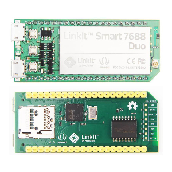
2.3. LinkIt Smart 7688 Duo The LinkIt Smart 7688 Duo development board is powered by the same MT7688AN SOC as the LinkIt Smart 7688, but includes an ATmega32U4 MCU. This supports additional features including Analog I/O support and Arduino IDE support. The board’s functionality is therefore a combination... - Page 20 MediaTek LinkIt™ Smart 7688 Developer's Guide Figure 7 LinkIt Smart 7688 Duo development board (MPU + MCU) 2.3.2. Buttons The buttons description on LinkIt Smart 7688 Duo and how to use them are described in Table 6. Scenario Button Action...
- Page 21 Please see section 2.2.3, “LEDs” for detailed information. In addition to the power and Wi-Fi LEDs, the LinkIt Smart 7688 Duo also has a LED that is tied to pin D13. D13 LED is controlled by the user Arduino program..
- Page 22 R95 and solder it to resistor R3 on the 7688 development board. After you’ve moved the resistor and reboot the device you’ll activate JTAG function. The steps are: Find a group of resistors on the bottom side of LinkIt Smart 7688 Duo (top-right view) as circled in Figure 8.
- Page 23 Figure 9, after you’re finished moving the resistor, restart the device and you should be able to access JTAG mode. Figure 9 Moving a resistor to access JTAG mode 2.3.10. Specifications The key specifications of the LinkIt Smart 7688 Duo development board are shown in Table 8. Category Feature LinkIt Smart 7688 Duo Chipset...
- Page 24 GPIO, PWM, I2C, I2S, SPI/SPIS, UART and more. The available pins for LinkIt Smart 7688 Duo are illustrated in Figure 10. For your convenience, this pin-out diagram is also downloadable from the MediaTek Labs website.
- Page 25 Figure 10 LinkIt Smart 7688 Duo Pin-out Diagram © 2015, 2016 MediaTek Inc. Page 25 This document contains information that is proprietary to MediaTek Inc. Unauthorized reproduction or disclosure of this information in whole or in part is strictly prohibited.
-
Page 26: Fcc, Ce And Ncc Certifications
MediaTek LinkIt™ Smart 7688 Developer's Guide 2.4. FCC, CE and NCC Certifications LinkIt Smart 7688 and LinkIt Smart 7688 Duo development boards are FCC, CE and NCC certified. For FCC compliance statement, please see Appendix A. © 2015, 2016 MediaTek Inc. -
Page 27: Programming Environment Guide
The high-level language development options enable you to build prototypes quickly. Since LinkIt Smart 7688 doesn’t have a display, you need to develop the high level programs remotely in a separate computer, conventionally called the host platform. Majority of the editing and development activities are performed on the host platform, the resulting programs are then transferred to LinkIt Smart 7688 for deployment and execution, the target platform. -
Page 28: Programming Model For Different Boards
Based on different levels of programmability and user scenarios, different software stacks and approaches can be used as shown in Figure 13. If you are using LinkIt Smart 7688 board, refer to chapter 5, “Peripheral Programming on LinkIt Smart 7688” to know how to connect to different devices and peripherals. -
Page 29: Choosing The Right Programming Model
3.5.1. Access Point Mode In AP mode a LinkIt Smart 7688 development board forms a LAN and acts as an access point, as shown in Figure 12. AP mode is used mainly to configure the board settings. Figure 12 LinkIt Smart 7688 in AP Mode 3.5.2. -
Page 30: Programming In C/C
3.6.1. Setting up C/C++ Programming Environment The cross compilation toolchain is included in the software package of LinkIt Smart 7688 SDK and supports Mac OS X and Linux. Windows isn’t supported at the time of writing. To use the toolchain, download and unzip it to a directory of your choice and denote the toolchain... -
Page 31: Programming In Python
3.7. Programming in Python High-level programming languages are executed by the corresponding languages interpreter in LinkIt Smart 7688. You can do the programming remotely and send the code to LinkIt Smart 7688 for execution. 3.7.1. Setting Up Python Programming Environment The high-level programming environment is simple. -
Page 32: Programming In Node.js
3.8. Programming in Node.js Node.js programming environment in LinkIt Smart 7688 is similar to Python - use a text editor and a file transfer tool to execute the program or use SSH to create your Node.js programs. Before you start, please make sure you’ve connected to LinkIt Smart 7688 via SSH. If you need more information please see section 4.5.4.1, “Using SSH (Secure Socket Shell)”. - Page 33 Node.js modules. To use it, first make sure your board is connected to the internet as described in section 4.6.5, “Connecting LinkIt Smart 7688 to a Wi-Fi Access Point To Access for a list of available packages. You can use npm Internet”...
-
Page 34: Software Development Kit And Related Tools
Set the options for a terminal device interface © 2015, 2016 MediaTek Inc. Page 34 This document contains information that is proprietary to MediaTek Inc. Unauthorized reproduction or disclosure of this information in whole or in part is strictly prohibited. -
Page 35: Opkg Packager Manager
LinkIt Smart 7688. The main opkg arguments used in the command line are as follows: • List Shows a list of packages currently installed on LinkIt Smart 7688. Example: $ opkg list-installed • Update Updates list of available packages. Before installing a new package please ensure to update the list of available package first. -
Page 36: System Configuration
$ opkg upgrade <pkgs| globp> Note: To perform opkg tasks such as install and upgrade, you’ll need to switch the LinkIt Smart 7688 to Station mode; this connects the device to the Internet. Please see section 3.5.2, “Station Mode” for more information. - Page 37 Power on LinkIt Smart development board by using any USB power source, for example your computer and a micro USB cable. LinkIt Smart 7688 Duo is used in Figure 14. Figure 14 Connecting LinkIt Smart development board to a computer Make sure you connect the cable to the Power (PWR) connector, not the USB host (HOST) connector near the MPU reset button.
- Page 38 After you’ve connected to LinkIt_Smart_7688 AP, the Wi-Fi LED will blink three times per second. If you have multiple LinkIt Smart 7688 boards, power only one of them to prevent name collision. An alternative is to insert a micro SD card with a file name which contains the name of Access Point you want to rename to.
- Page 39 MediaTek LinkIt™ Smart 7688 Developer's Guide the Internet in later steps. But first, you need to configure LinkIt Smart 7688 and the steps are described next. Figure 17 LinkIt Smart 7688 in AP mode http://mylinkit.local , as shown in Figure 18.
- Page 40 Using SSH (Secure Socket Shell) Before you start please make sure you’ve already set a password in the Web UI as described in section 4.5.3, “Connecting to the Web UI” and the LinkIt Smart 7688 is in the same network as your computer.
- Page 41 Enter the password you set previously in the Web UI. © 2015, 2016 MediaTek Inc. Page 41 This document contains information that is proprietary to MediaTek Inc. Unauthorized reproduction or disclosure of this information in whole or in part is strictly prohibited.
- Page 42 Using Serial to USB Cable You can connect to the system console of LinkIt Smart 7688 by using a Serial (or UART) to USB cable. First, you need to check if your cable requires driver installation; it may or may not be needed.
- Page 43 MediaTek LinkIt™ Smart 7688 Developer's Guide Figure 22 LinkIt Smart 7688 COM port using Serial to USB cable Open the PuTTY terminal and enter the COM port number of the USB device found in the device manager, click on the Serial radio button, type 57600 in Speed box and click Open, as shown in Figure 23.
- Page 44 Install the driver if needed. Check the cable manufacturer’s website for driver requirements on Mac and installation instructions. Plug-in the cable and connect the cable to LinkIt Smart 7688. Open a Terminal session. You can open it at Applications/Utilities/Terminal. Type ls /dev/cu* in the Terminal. You should see a list of devices. Look for something like cu.usbserial-XXXXXXXX where XXXXXXXX is usually a random identifier.
-
Page 45: System Configuration Tasks
Now you should be connected to the system console. Press ENTER in the Terminal to bring up the prompt. You'll notice that the prompt has become different from your OS X Terminal application, it is the LinkIt Smart 7688 prompt and it looks like the following: root@myLinkIt:/# You’re ready to make changes to the LinkIt Smart 7688 system through this console. - Page 46 LinkIt Smart 7688 and Duo boards. • Using Web UI: Sign in the LinkIt Smart 7688 Web UI. Please see section 4.5.3, “Connecting to the Web UI” if you haven’t signed in before. After you’ve signed in, click on the Upgrade firmware as shown in Figure 24.
- Page 47 Restart Figure 27 Wi-Fi LED Status During Firmware Upgrade LinkIt Smart 7688 will start to read the firmware image (Wi-Fi LED blinks fast) and perform the firmware upgrade process (Wi-Fi LED blinks slowly). This process takes about 3 minutes to finish.
- Page 48 • Using the Wi-Fi Reset button After LinkIt Smart 7688 is boot up (power LED solid on, Wi-Fi LED), press the Wi-Fi Reset button for at least 20 seconds and release. Please see Figure 3 and Figure 9 for Wi-Fi Reset button locations.
- Page 49 This section describes how LinkIt Smart 7688 development board connects to an AP in a Wi-Fi network to access the Internet. To connect to an access point, LinkIt Smart 7688 needs to be in Station mode. For more information please see section3.5, “Network Environment”.
- Page 50 Using the System Console In order for LinkIt Smart 7688 board to access the Internet, it needs to join a network that has an access point connected to the Internet, and to do that, the board needs to be in Station mode.
- Page 51 Viewing System Information from the Web UI You can view LinkIt Smart 7688’s system information from any browser. After you’ve connected the LinkIt Smart 7688 to a network, open a browser and type http://mylinkit.local in the URL box © 2015, 2016 MediaTek Inc.
- Page 52 4.6.7. Accessing the USB drive and the SD Card When a USB drive or SD card is inserted into LinkIt Smart 7688, they can be accessed under /Media/SD* or /Media/USB* (The device name displayed varies depending on the number of drives you use and the number of partitions available on the USB drive or SD card).
-
Page 53: File Editor And Transfer
As a developer, you want freedom to use any text editor of your choice for coding. You can launch the built-in vim editor in system console to edit source code files directly in LinkIt Smart 7688 or you can use other editor from a remote computer, but during development, including tasks such as program execution, it’s common to transfer files between LinkIt Smart 7688 and the remote... - Page 54 Figure 34 WinSCP login window c) Locate the file you want to transfer on the left pane (your computer) and drag it to the right (LinkIt Smart 7688), as shown in Figure 35. Figure 35 File transfer using WinSCP d) After you’ve dragged the file, an Upload window will appear as shown in Figure 36 asking you to confirm the upload.
- Page 55 In the above example, a file named helloworld from the current directory is copied to the path /example/helloworld in LinkIt Smart 7688. The SCP tool will instruct you to enter the password of root account, which is setup in section 3.4.1, “Accessing Web based configuration tools”.
- Page 56 MediaTek LinkIt™ Smart 7688 Developer's Guide 4.7.4. Setup Samba service in LinkIt Smart 7688 Samba is a file transfer tool that is built-in LinkIt Smart 7688 and provides a shared folder /Media on the device for file transfer. In the example below you’ll learn how to use UCI command to change the shared folder to and set appropriate access permission for this folder.
- Page 57 Open Finder and in the top menu click Go > Connect to server as shown in Figure 38. Figure 38 Connecting to LinkIt Smart 7688 from Finder In the server address field, type smb://mylinkit.local and click Connect, as shown in Figure ©...
- Page 58 Figure 41 MyShareFolder in Mac Finder © 2015, 2016 MediaTek Inc. Page 58 This document contains information that is proprietary to MediaTek Inc. Unauthorized reproduction or disclosure of this information in whole or in part is strictly prohibited.
-
Page 59: Peripheral Programming On Linkit Smart 7688
How to Access LinkIt Smart 7688 Peripheral using MRAA Libmraa is a C/C++ library to interface with the peripheral on LinkIt Smart 7688. Libmraa is pre- installed in the system image of LinkIt Smart 7688 and supports Python, Javascript and Node.js languages. - Page 60 5.1.1. Installing MRAA Libmraa is already installed in the system image of LinkIt Smart 7688, so you don't need to install it again. However if you want to update the library, or want to port or upgrade the library, please...
- Page 61 # Refer to the pinout digram for the GPIO number to silk print mapping # in this example the number 2 maps to P10 on LinkIt Smart 7688 board pin = mraa.Gpio(2) pin.dir(mraa.DIR_IN) while True: print "P10...
- Page 62 The way I2Cs are initialized is slightly different from GPIO modules - instead of using pins, I2Cs are initialized according to its device index. Since there is only 1 set of I2C master device on LinkIt Smart 7688, you can simply pass 0 - and it is always on pin GPIO4...
- Page 63 "Grove - 3-Axis Digital Accelerometer not found" For more details on I2C API, please see here. To drive an I2C device, you need to operate multiple I2C sequences. LinkIt Smart 7688 also comes with libUPM pre-installed, which is a set of driver repository built upon libmraa.
- Page 64 This example shows you how to use mraa library in Node.js to make the Wi-Fi LED on LinkIt Smart 7688 blink. Connect to LinkIt Smart 7688 console using SSH. In the system console, create a directory app and then switch into the directory. For example:...
- Page 65 Press :wq! to save the app.js file. © 2015, 2016 MediaTek Inc. Page 65 This document contains information that is proprietary to MediaTek Inc. Unauthorized reproduction or disclosure of this information in whole or in part is strictly prohibited.
-
Page 66: How To Use Upm To Access Sensors And Peripherals
I2C grove interface. If not, you can also connect the pins from the accelerometer to the corresponding pins GND, 3V3, SDA (P20) and SCL (P21) on LinkIt Smart 7688 board. Import pyupm_adxl345 module from the UPM repository in your program, you’ll do this in the next step. - Page 67 © 2015, 2016 MediaTek Inc. Page 67 This document contains information that is proprietary to MediaTek Inc. Unauthorized reproduction or disclosure of this information in whole or in part is strictly prohibited.
-
Page 68: Peripheral Programming On Linkit Smart 7688 Duo
ATmega32U4 microcontroller on LinkIt Smart 7688 Duo and the microcontroller on LinkIt Smart 7688 Duo is preloaded with boot loader that supports Arduino IDE programming. Therefore, the following sections will begin with introduction on how to setup the Arduino IDE,... - Page 69 MediaTek LinkIt™ Smart 7688 Developer's Guide Figure 45 LinkIt Smart 7688 package URL for a custom board installation in Arduino IDE Make sure your computer is connected to the internet. In the Arduino Tools menu point to Board then click Boards Manager as shown in Figure...
- Page 70 Error downloading the LinkIt ONE SDK package There should now be a LinkIt Smart 7688 item appearing in the boards list on the Boards Manager as shown in Figure 47. Click the LinkIt Smart 7688 version button to select the latest and click Install.
- Page 71 Figure 48 LinkIt Smart 7688 board package installed on Arduino IDE If there is a problem with the LinkIt Smart 7688 board package installation, try installing Arduino SAM board package first, as shown below. Then retry LinkIt Smart 7688 installation.
-
Page 72: Installing Linkit Smart 7688 Duo Com Port Driver
Installing LinkIt Smart 7688 Duo COM Port Driver After you’ve installed the board package, connect LinkIt Smart 7688 Duo to your computer and you should see a USB serial COM port in the device manager with the following port ID: •... -
Page 73: Programming Model For Linkit Smart 7688 Duo
The number 0 may be different on each Ubuntu machine. • For OS X, it’s also not required to install a driver, LinkIt Smart 7688 Duo is mounted as a /dev/tty.usbmodem1413 1413 serial device under . The number may be different on each OS X machine. - Page 74 Firmata implementations has been used to date. Therefore, those whom are familiar with MPU © 2015, 2016 MediaTek Inc. Page 74 This document contains information that is proprietary to MediaTek Inc. Unauthorized reproduction or disclosure of this information in whole or in part is strictly prohibited.
- Page 75 For Arduino Yun developers, the MPU Linux side acts as a black box for simply providing Wi-Fi connectivity and USB / SD peripheral accessibility. LinkIt Smart 7688 Duo also provides Arduino Yun Bridge library implementation for developers to build their projects the way they are familiar with, as shown in Figure 55.
-
Page 76: Programming With Primitive Uart Connection
6.5. Programming with Primitive UART Connection In all the scenarios described in previous section, the MPU and MCU on LinkIt Smart 7688 Duo communicates using Serial port. The MCU communicates with OpenWrt Linux over UART hardware. Table 17 illustrates the communication between MCU and MPU:... - Page 77 = None def setup(): © 2015, 2016 MediaTek Inc. Page 77 This document contains information that is proprietary to MediaTek Inc. Unauthorized reproduction or disclosure of this information in whole or in part is strictly prohibited.
-
Page 78: Programming With Firmata Protocol
Table 18 Serial Pin Mapping Between MPU and MCU © 2015, 2016 MediaTek Inc. Page 78 This document contains information that is proprietary to MediaTek Inc. Unauthorized reproduction or disclosure of this information in whole or in part is strictly prohibited. - Page 79 MediaTek LinkIt™ Smart 7688 Developer's Guide 6.6.2. Prototype The diagram, as shown in Figure 57, illustrates how the MPU and MCU in LinkIt Smart 7688 Duo communicate with each other using Firmata protocol and Python. Figure 57 MPU MCU Communication Diagram 6.6.3.
- Page 80 Duo supports version pymata-2.1. Note: The LinkIt Smart 7688 Duo needs to be in Station mode in order to use pip to install the pyFirmata and PyMata interface, please see section 4.3.2, “Station Mode” for details on how to set station mode.
- Page 81 Now execute this Python script and you should see following message: $python ./blink_with_firmata.py Start blinking D13 If you see the LED on of the LinkIt Smart 7688 Duo blink accordingly, congratulations. You’ve successfully ran the blink example. To terminate the Python program, press Ctrl-C. 6.6.5.
- Page 82 PyMata close(): Calling sys.exit(0): Hope to see you soon! © 2015, 2016 MediaTek Inc. Page 82 This document contains information that is proprietary to MediaTek Inc. Unauthorized reproduction or disclosure of this information in whole or in part is strictly prohibited.
- Page 83 MediaTek LinkIt™ Smart 7688 Developer's Guide If you see the LED on of the LinkIt Smart 7688 Duo blink 10 times before the Python program terminates, congratulations. You’ve successfully ran the blink example. Please continue to explore more examples in the PyMata/examples you’ve downloaded earlier.
- Page 84 Figure 59 Uploading example sketch in Arduino IDE Set up the MPU, for this you’ll need to install Firmata on your computer. While you can install Firmata using NPM on LinkIt Smart 7688 Duo, the process is a bit long, that’s why you should install...
- Page 85 Use scp to transfer the compressed file to LinkIt Smart 7688 Duo $ scp ./firmata.tar root@mylinkit.local:/root/app/node_modules Open the LinkIt Smart 7688 Duo SSH system console and type the following commands to create a directory called app and go to that directory.
- Page 86 Open a browser and enter the following commands to control the LED: a) To turn LED ON: mylinkit.local:8080?value=high b) To turn LED OFF: mylinkit.local:8080?value=low The D13 LED on LinkIt Smart 7688 Duo should blink according to your command of choice. 6.6.7. Cylon.js example This section illustrates the MPU and MCU communication using Firmata in Cylon.js programming...
- Page 87 MediaTek LinkIt™ Smart 7688 Developer's Guide needed to communicate with the hardware attached to Arduino. While you can install Firmata and Cylon using NPM on LinkIt Smart 7688 Duo, the process is a bit long, that’s why you should install on your computer instead and install Firmata and the Cylon modules from there.
- Page 88 This chapter introduces the methods you can use to program the boot loader on the ATmega32U4. LinkIt Smart 7688 Duo is pre-programmed with Arduino boot loader in the microcontroller (ATmega32U4). You are not required to program the boot loader, but in the event the boot loader is damaged or requires re-programming, you can use one of the following methods to update the boot loader.
- Page 89 Using LinkIt Smart 7688 Duo to program boot loader on another LinkIt Smart 7688 Duo In the following example, there are two LinkIt Smart 7688 Duo boards called A and B. The first board A will act as the programmer to program the second board B.
-
Page 90: Programming With Yun Bridge Library
Arduino IDE, then choose File > Examples > Bridge > TimeCheck. Next, upload the TimeCheck example sketch to LinkIt Smart 7688 Duo and launch the Serial Monitor. You should see following outputs from the Serial Monitor. - Page 91 © 2015, 2016 MediaTek Inc. Page 91 This document contains information that is proprietary to MediaTek Inc. Unauthorized reproduction or disclosure of this information in whole or in part is strictly prohibited.
-
Page 92: Troubleshooting Guide
If you’re using the Web UI to upgrade firmware, please make sure you’ve checked the following: • The power source was steadily supplied to LinkIt Smart 7688 during firmware upgrade. Do not unplug the USB drive or disconnect the USB cable during firmware upgrade process or else your board will fail to boot up. -
Page 93: I'm Not Able To Ssh Access With An Error Showing "Host Identification Has Changed", What Can I Do
If you see an error message similar to below as shown in Figure 58: Figure 62 Host ID change warning It indicates you’ve used a different LinkIt Smart 7688 board or upgraded a new firmware and tried to access system console using SSH. The new firmware or different board creates a new host identification which is different from the previous one, hence the error. - Page 94 MediaTek LinkIt™ Smart 7688 Developer's Guide 7.5. There are multiple LinkIt Smart 7688 APs nearby and I’m not sure which one is mine, how do I find out? To find the hardware address of the board, type ifconfig in the system console. The hardware address should show in the first sentence under ra0, as shown in Figure 64.
- Page 95 Labs forum for posts on possible causes and cures. © 2015, 2016 MediaTek Inc. Page 95 This document contains information that is proprietary to MediaTek Inc. Unauthorized reproduction or disclosure of this information in whole or in part is strictly prohibited.
- Page 96 OEM integrator is still responsible for testing their end-product for any additional compliance requirements required with this module installed © 2015, 2016 MediaTek Inc. Page 96 This document contains information that is proprietary to MediaTek Inc. Unauthorized reproduction or disclosure of this information in whole or in part is strictly prohibited.
- Page 97 The end user manual shall include all required regulatory information/warning as show in this manual. © 2015, 2016 MediaTek Inc. Page 97 This document contains information that is proprietary to MediaTek Inc. Unauthorized reproduction or disclosure of this information in whole or in part is strictly prohibited.
Need help?
Do you have a question about the LinkIt Smart 7688 and is the answer not in the manual?
Questions and answers