Endress+Hauser Micropilot FMR51 Technical Information
Free space radar
Hide thumbs
Also See for Micropilot FMR51:
- Operating instructions manual (198 pages) ,
- Technical information (96 pages) ,
- Brief operating instructions (48 pages)
Table of Contents
Advertisement
TI01040F/00/EN/08.17
71375707
Products
Technical Information
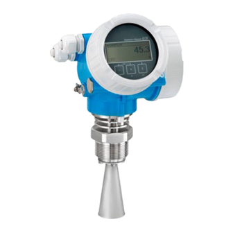
Micropilot FMR51, FMR52
Free space radar
Level measurement in liquids
Application
• Continuous, non-contact level measurement of liquids, pastes and slurries
• Horn antenna (FMR51); flush mounted, completely filled PTFE horn antenna
(FMR52)
• Maximum measuring range: 70 m (230 ft)
• Temperature: –196 to +450 °C (–321 to +842 °F)
• Pressure: –1 to +160 bar (–14.5 to +2 320 psi)
• Accuracy: ± 2 mm
• International explosion protection certificates; WHG; marine approvals
• Linearity protocol (3-point, 5-point)
Your benefits
• Reliable measurement even for changing product and process conditions
• HistoROM data management for easy commissioning, maintenance and
diagnostics
• Highest reliability due to Multi-Echo Tracking
• SIL2 according to IEC 61508, SIL3 in case of homogeneous or heterogeneous
redundancy
• Seamless integration into control or asset management systems
• Intuitive user interface in national languages
• Easy proof test for SIL and WHG
• Heartbeat Technology™
Solutions
Services
Advertisement
Table of Contents

Related Manuals for Endress+Hauser Micropilot FMR51


Summary of Contents for Endress+Hauser Micropilot FMR51
- Page 1 Products Solutions Services TI01040F/00/EN/08.17 71375707 Technical Information Micropilot FMR51, FMR52 Free space radar Level measurement in liquids Application • Continuous, non-contact level measurement of liquids, pastes and slurries • Horn antenna (FMR51); flush mounted, completely filled PTFE horn antenna (FMR52) •...
-
Page 2: Table Of Contents
Micropilot FMR51, FMR52 Table of contents Important document information ....4 Degree of protection ...... - Page 3 Micropilot FMR51, FMR52 Tagging (TAG) ......Services ........99 Application Packages .
-
Page 4: Important Document Information
Micropilot FMR51, FMR52 Important document information Symbols Safety symbols Symbol Meaning DANGER! This symbol alerts you to a dangerous situation. Failure to avoid this situation will DANGER result in serious or fatal injury. WARNING! This symbol alerts you to a dangerous situation. Failure to avoid this situation can WARNING result in serious or fatal injury. - Page 5 Micropilot FMR51, FMR52 Symbols in graphics Symbol Meaning 1, 2, 3 ... Item numbers … Series of steps A, B, C, ... Views A-A, B-B, C-C, ... Sections Hazardous area Indicates a hazardous area. Safe area (non-hazardous area) Indicates the non-hazardous area.
-
Page 6: Function And System Design
Micropilot FMR51, FMR52 Function and system design Measuring principle The Micropilot is a "downward-looking" measuring system, operating based on the time-of-flight method (ToF). It measures the distance from the reference point (process connection) to the product surface. Radar impulses are emitted by an antenna, reflected off the product surface and received again by the radar system. - Page 7 • Measurement unaffected by medium properties • Hardware and software developed according to SIL IEC 61508 Procurement • Endress+Hauser being the world market leader in level measurement guarantees asset protection • Worldwide support and service Installation • Special tools are not required •...
-
Page 8: Input
Treat Ammonia NH as a medium of group A. For dielectric constants (DC values) of many media commonly used in various industries refer • the Endress+Hauser DC manual (CP01076F) • the Endress+Hauser "DC Values App" (available for Android and iOS) Endress+Hauser... - Page 9 Micropilot FMR51, FMR52 Device Storage tank A0018833 Calm product surface (e.g. intermittent filling, filling from bottom, immersion tubes) Antenna size FMR51 40 mm (1½ in) 50 mm (2 in) 80 mm (3 in) 100 mm (4 in) FMR52 50 mm (2 in) 80 mm (3 in) (9.9)
- Page 10 Micropilot FMR51, FMR52 Device Buffer tank A0018835 Moving surfaces (e.g. continuous filling, from above, mixing jets) Antenna size FMR51 40 mm (1½ in) 50 mm (2 in) 80 mm (3 in) 100 mm (4 in) FMR52 50 mm (2 in) 80 mm (3 in) (6.6)
- Page 11 Micropilot FMR51, FMR52 Device Process tank with agitator A0018837 Turbulent surface (e.g. filling from above, agitators, baffles) Antenna size FMR51 40 mm (1½ in) 50 mm (2 in) 80 mm (3 in) 100 mm (4 in) FMR52 50 mm (2 in) 80 mm (3 in) (3.2)
- Page 12 Micropilot FMR51, FMR52 Device Stilling well Bypass A0018840 A0018842 Antenna size Antenna size FMR51 40 ... 100 mm ( 1½ ... 4 in) 40 ... 100 mm ( 1½ ... 4 in) FMR52 50 ... 80 mm ( 2 ... 3 in) 50 ...
-
Page 13: Operating Frequency
Micropilot FMR51, FMR52 Operating frequency K-band (~ 26 GHz) Up to 8 Micropilot transmitters can be installed in the same tank because the transmitter pulses are statistically coded. Transmitting power Distance Average energy density in beam direction Standard version With "Advanced dynamics" application package 1 m (3.3 ft) -
Page 14: Output
Micropilot FMR51, FMR52 Output Output signal HART Signal coding FSK ±0.5 mA over current signal Data transmission rate 1 200 Bit/s Galvanic isolation PROFIBUS PA Signal coding Manchester Bus Powered (MBP) Data transmission rate 31.25 kBit/s, voltage mode Galvanic isolation... -
Page 15: Signal On Alarm
Micropilot FMR51, FMR52 Signal on alarm Depending on the interface, failure information is displayed as follows: • Current output (for HART devices) – Failsafe mode selectable (in accordance with NAMUR Recommendation NE 43): Minimum alarm: 3.6 mA Maximum alarm (= factory setting): 22 mA –... - Page 16 Micropilot FMR51, FMR52 Multidrop current 4.0 mA Set-up time 15 s PROFIBUS PA Manufacturer ID 17 (0x11) Ident number 0x1559 Profile version 3.02 GSD file Information and files under: • www.endress.com GSD file version • www.profibus.org Output values Analog Input: •...
- Page 17 Micropilot FMR51, FMR52 Link Master / Basic Device selectable yes; default: Basic Device Node address Default: 247 (0xF7) Features supported Following methods are supported: • Restart • ENP Restart • Setup • Linearization • Self Check Virtual Communication Relationships (VCRs)
- Page 18 Micropilot FMR51, FMR52 Function Blocks Block Content Number of Number of Execution Functionality permanent instantiable time blocks blocks Resource Block The Resource Block contains all the enhanced data that uniquely identifies the field device. It is an electronic version of a nameplate of the device.
- Page 19 Micropilot FMR51, FMR52 Block Content Number of Number of Execution Functionality permanent instantiable time blocks blocks Integrator The Integrator Function Block 25 ms standard Block integrates a variable as a function of the time or accumulates the counts from a Pulse Input block.
-
Page 20: Power Supply
Micropilot FMR51, FMR52 Power supply Terminal assignment 2-wire: 4-20mA HART – – 4...20 mA – – 4...20 mA A0011294 2 Terminal assignment 2-wire; 4-20mA HART Without integrated overvoltage protection With integrated overvoltage protection Active barrier with power supply (e.g. RN221N): Observe terminal voltage HART communication resistor (≥... - Page 21 Micropilot FMR51, FMR52 2-wire: 4-20mA HART, switch output – ≥250 Ω 4...20 mA – ≥250 Ω 4...20 mA A0013759 3 Terminal assignment 2-wire; 4-20mA HART, switch output Without integrated overvoltage protection With integrated overvoltage protection Active barrier with power supply (e.g. RN221N): Observe terminal voltage HART communication resistor (≥...
- Page 22 Micropilot FMR51, FMR52 2-wire: 4-20mA HART, 4-20mA – 4...20 mA – 4...20 mA – 4...20 mA – 4...20 mA A0013923 4 Terminal assignment 2-wire, 4-20 mA HART, 4...20mA Without integrated overvoltage protection With integrated overvoltage protection Connection current output 2 Connection current output 1 Supply voltage for current output 1 (e.g.
- Page 23 Micropilot FMR51, FMR52 4-wire: 4-20mA HART (10.4 to 48 V ≥250 Ω 4...20 mA A0011340 5 Terminal assignment 4-wire; 4-20mA HART (10.4 to 48 V Evaluation unit, e.g. PLC HART communication resistor (≥ 250 Ω): Observe maximum load Connection for Commubox FXA195 or FieldXpert SFX350/SFX370 (via VIATOR Bluetooth modem)
- Page 24 Micropilot FMR51, FMR52 4-wire: 4-20mA HART (90 to 253 V ≥250 Ω 4...20 mA A0018965 6 Terminal assignment 4-wire; 4-20mA HART (90 to 253 V Evaluation unit, e.g. PLC HART communication resistor (≥ 250 Ω): Observe maximum load Connection for Commubox FXA195 or FieldXpert SFX350/SFX370 (via VIATOR Bluetooth modem)
- Page 25 Micropilot FMR51, FMR52 PROFIBUS PA / FOUNDATION Fieldbus A0011341 7 Terminal assignment PROFIBUS PA / FOUNDATION Fieldbus Without integrated overvoltage protection With integrated overvoltage protection Cable screen: Observe cable specifications Switch output (open collector): Terminals 3 and 4 PROFIBUS PA / FOUNDATION Fieldbus: Terminals 1 and 2...
- Page 26 Micropilot FMR51, FMR52 Connection examples for the switch output For HART devices, the switch output is available as an option. See product structure, feature 20: "Power Supply, Output", option B: "2-wire; 4-20mA HART, switch output" Devices with PROFIBUS PA and FOUNDATION Fieldbus always have a switch output.
-
Page 27: Device Plug Connectors
Micropilot FMR51, FMR52 Device plug connectors For the versions with fieldbus plug connector (M12 or 7/8"), the signal line can be connected without opening the housing. Pin assignment of the M12 plug connector Meaning Signal + not connected Signal -... -
Page 28: Supply Voltage
Micropilot FMR51, FMR52 Supply voltage An external power supply is required. Various supply units can be ordered from Endress+Hauser: see "Accessories" section→ 109 2-wire, 4-20mA HART, passive "Power Supply, Output" "Approval" Terminal voltage U at the Maximum load R, depending on the supply voltage U... - Page 29 Micropilot FMR51, FMR52 "Power Supply, Output" "Approval" Terminal voltage U at the Maximum load R, depending on the supply voltage U at the device supply unit C: 2-wire; 4-20mA HART, 13 to 28 V R [ ] 4-20mA U 0 [V]...
-
Page 30: Power Consumption
Micropilot FMR51, FMR52 4-wire, 4-20mA HART, active "Power supply; Output" Terminal voltage Maximum load K: 4-wire 90-253VAC; 4-20mA HART 90 to 253 V (50 to 60 Hz), 500 Ω overvoltage category II L: 4-wire 10,4-48VDC; 4-20mA HART 10.4 to 48 V... -
Page 31: Power Supply Failure
Micropilot FMR51, FMR52 FOUNDATION Fieldbus Device basic current 15 mA Error current FDE (Fault 0 mA Disconnection Electronic) FISCO 17.5 V 550 mA 5.5 W 5 nF 10 μH Power supply failure • Configuration is retained in the HistoROM (EEPROM). -
Page 32: Overvoltage Protection
< 1.5 pF Nominal arrest impulse voltage (8/20 μs) 10 kA External overvoltage protection HAW562 or HAW569 from Endress+Hauser are suited as external overvoltage protection. For detailed information please refer to the following documents: • HAW562: TI01012K • HAW569: TI01013K... -
Page 33: Performance Characteristics
Micropilot FMR51, FMR52 Performance characteristics Reference operating • Temperature = +24 °C (+75 °F) ±5 °C (±9 °F) conditions • Pressure = 960 mbar abs. (14 psia) ±100 mbar (±1.45 psi) • Humidity = 60 % ±15 % • Reflector: metal plate with a minimum diameter of 1 m (40 in) •... -
Page 34: Measured Value Resolution
Micropilot FMR51, FMR52 20 (0.79) 3 (0.12) -3 (-12) -20 (-0.79) 2 (6.6) D [m] ([ft]) A0019034 11 Maximum measured error in near-range applications; values for version with the "Advanced dynamics" application package Δ Maximum measured error Lower edge of the antenna... -
Page 35: Gas Phase Compensation With External Pressure Sensor (Profibus Pa, Foundation Fieldbus)
Micropilot FMR51, FMR52 error for a few typical gases/vapors (with regard to distance; a positive value means that too large a distance is being measured): Gas layer Temperature Pressure °C °F 1 bar (14,5 psi) 10 bar (145 psi) 50 bar (725 psi) -
Page 36: Installation
Micropilot FMR51, FMR52 Installation Installation conditions Mounting position • Recommended distance A from wall to outer edge of nozzle: ~ 1/6 of tank diameter. Nevertheless the device should not be installed closer than 15 cm (5.91 in) to the tank wall. - Page 37 If the outer wall of the vessel is made of a non-conductive material (e.g. GRP), microwaves can also be reflected off interfering installations outside the vessel (e.g. metallic pipes (1), ladders (2), grates (3), ...). Therefore, there should be no such interfering installations in the signal beam. Please contact Endress+Hauser for further information. A0017123 Endress+Hauser...
- Page 38 Micropilot FMR51, FMR52 Optimization options • Antenna size The bigger the antenna, the smaller the beam angle α and the fewer interference echoes → 38. • Mapping The measurement can be optimized by means of electronic suppression of interference echoes.
- Page 39 Micropilot FMR51, FMR52 Beam diameter W as a function of beam angle α and measuring distance D: FMR51 Antenna size 40 mm (1½ in) 50 mm (2 in) 80 mm (3 in) 100 mm (4 in) Beam angle α 23°...
-
Page 40: Measuring Conditions
Micropilot FMR51, FMR52 Measuring conditions • In case of boiling surfaces, bubbling or tendency for foaming use FMR53 or FMR54. Depending on its consistence, foam can either absorb microwaves or reflect them off the foam surface. Measurement is possible under certain conditions. For FMR50, FMR51 and FMR52, the additional option "Advanced dynamics"... -
Page 41: Mounting Cladded Flanges
Micropilot FMR51, FMR52 Mounting cladded flanges • Use flange screws according to the number of flange holes. • Tighten the screws with the required torque (see table). • Retighten the screws after 24 hours or after the first temperature cycle. - Page 42 Micropilot FMR51, FMR52 ° ° ° ° ° ° A0018974 Depending on the device version the marking may be a circle or two short parallel lines. Nozzle mounting For optimum measurement, the tip of the antenna should extend below the nozzle. Depending on...
- Page 43 • The nozzle end must be smooth and free of burrs. If possible its edge should be rounded. • An interference echo suppression must be performed. • Please contact Endress+Hauser for applications with higher nozzles than those indicated in the table.
- Page 44 Micropilot FMR51, FMR52 Suitable thickness of the tank ceiling: Penetrated material PTFE Perspex DK / ε Optimum thickness 3.8 mm (0.15 in) 4.0 mm (0.16 in) 3.8 mm (0.15 in) 3.3 mm (0.13 in) Other possible values for the thickness are multiples of the values listed (e.g. for PE: 7,6 mm (0.3 in), 11,4 mm (0.45 in)
-
Page 45: Installation In Stilling Well
BP: Horn 80mm/3" 500 mm (19.7 in) Feature 070 of the product structure Please contact Endress+Hauser for applications with higher nozzle. • For flanges with PTFE cladding: Observe the notes on the mounting of cladded flanges → 41. • Usually, the PTFE flange cladding also serves as a seal between the nozzle and the device flange. - Page 46 Micropilot FMR51, FMR52 Examples for the construction of stilling wells 100% 100% mm (in) A0019009 Micropilot FMR50/FMR51: Horn 40mm(1½") Micropilot FMR50/FMR51/FMR52/FMR54: Horn 80mm(3") Stilling well with slots Full bore ball valve Marking for axial alignment Threaded connection e.g. welding neck flange DIN2633 ...
-
Page 47: Installation In Bypass
Micropilot FMR51, FMR52 Installation in bypass A0019446 16 Installation in bypass Marking for antenna alignment Tank connectors • Alighn the marker perpendicular (90°) to the tank connectors. • Measurements can be performed through an open full bore ball valve without any problems. - Page 48 Micropilot FMR51, FMR52 Example for the construction of a bypass 100% mm (in) A0019010 Micropilot FMR50/FMR51/FMR52/FMR54: Horn 80mm(3") Full bore ball valve Minimum distance to upper connection pipe: 400 mm (15,7 in) Marking for axial alignment e.g. welding neck flange DIN2633 Diameter of the connection pipes as small as possible Do not weld through the pipe wall;...
-
Page 49: Vessels With Heat Insulation
Micropilot FMR51, FMR52 Vessels with heat insulation A0019142 If process temperatures are high, the device must be included in normal tank insulation to prevent the electronics heating up as a result of heat radiation or convection. The insulation may not exceed beyond the neck of the housing. -
Page 50: Environment
Micropilot FMR51, FMR52 Environment Ambient temperature range Measuring device –40 to +80 °C (–40 to +176 °F); –50 °C (–58 °F) with manufacturer declaration on request Local display –20 to +70 °C (–4 to +158 °F), the readability of the display may be impaired at temperatures outside the temperature range. - Page 51 Micropilot FMR51, FMR52 FMR51 Seal: • Viton GLT, –40 to 150 °C (–40 to 302 °F) • Kalrez, –20 to 150 °C (–4 to 302 °F) Housing: GT18 (316 L) Temperature unit: °C (°F) A0019351 Power Supply; Output (Pos. 2...
- Page 52 Micropilot FMR51, FMR52 FMR51 Seal: • Viton GLT, –40 to 150 °C (–40 to 302 °F) • Kalrez, –20 to 150 °C (–4 to 302 °F) Housing: GT20 (Alu, coated) Temperature unit: °C (°F) A0019351 Power Supply; Output (Pos. 2...
- Page 53 Micropilot FMR51, FMR52 FMR51 Seal: Graphite, –40 to 250 °C (–40 to 482 °F) Housing: GT19 (Plastics PBT) Temperature unit: °C (°F) A0019351 Power Supply; Output (Pos. 2 of the product structure) (-40) (176) (176) (176) (482) (111) (482) (-40)
- Page 54 Micropilot FMR51, FMR52 FMR51 Seal: Graphite, –196 to 450 °C (–321 to 842 °F) Housing: GT18 (316 L) Temperature unit: °C (°F) A0019344 Power Supply; Output (Pos. 2 of the product structure) -196 -196 (-321) (178) (178) (178) (842) (79)
- Page 55 Micropilot FMR51, FMR52 FMR51 Seal: Graphite, –196 to 450 °C (–321 to 842 °F) Housing: GT20 (Alu, coated) Temperature unit: °C (°F) A0019344 Power Supply; Output (Pos. 2 of the product structure) -196 -196 (-321) (178) (178) (178) (842) (102)
- Page 56 Micropilot FMR51, FMR52 FMR52 Antenna: Horn 50mm/2" Housing: GT19 (Plastics PBT) Temperature unit: °C (°F) A0019351 Power Supply; Output (Pos. 2 of the product structure) (-40) (176) (176) (176) (392) (108) (392) (-40) (-40) (-40) Switch output not used (-40)
- Page 57 Micropilot FMR51, FMR52 FMR52 Antenna: Horn 80mm/2" Housing: GT18 (316 L) Temperature unit: °C (°F) A0019351 Power Supply; Output (Pos. 2 of the product structure) (-40) (178) (178) (178) (392) (135) (392) (-40) (-40) (-40) Switch output not used (-40)
-
Page 58: Storage Temperature
Micropilot FMR51, FMR52 FMR52 Antenna: Horn 80mm/2" Housing: GT20 (Alu, coated) Temperature unit: °C (°F) A0019351 Power Supply; Output (Pos. 2 of the product structure) (-40) (178) (178) (178) (392) (142) (392) (-40) (-40) (-40) Switch output not used (-40) -
Page 59: Electromagnetic Compatibility (Emc)
Micropilot FMR51, FMR52 hose-down cleaning. The material compatibility has to be considered if cleaning agents are used! The maximum permitted temperature at the flange should not be exceeded. Electromagnetic Electromagnetic compatibility to all relevant requirements of the EN 61326- series and NAMUR compatibility (EMC) recommendation EMC (NE21). -
Page 60: Process
Micropilot FMR51, FMR52 Process Process temperature, Process The specified pressure range may be reduced due to the selected process connection. The pressure pressure rating (PN) specified on the flanges refers to a reference temperature of 20 °C, for ASME flanges 100 °F. Pay attention to pressure-temperature dependencies. - Page 61 Micropilot FMR51, FMR52 [bar] ([psi]) 160 (2320) 154 (2233) 148 (2146) 142 (2059) [°C] -196 -100 +310 +350 +400 +450 (-321) (-148) (+32) (+590) (+662) (+752) (+842) ([°F]) A0020555-EN 18 FMR51: Admissible range of process temperature and process pressure of the HT version (Feature 090 "Seal", Option D2)
-
Page 62: Dielectric Constant
≥ 1.4 in stilling well • For bulk solids ε ≥ 1.6 For dielectric constants (DC values) of many media commonly used in various industries refer • the Endress+Hauser DC manual (CP01076F) • the Endress+Hauser "DC Values App" (available for Android and iOS) Endress+Hauser... -
Page 63: Mechanical Construction
Micropilot FMR51, FMR52 Mechanical construction Dimensions Dimensions of the electronics housing 98 (3.86)* 78 (3.07) 90 (3.54) A0011666 20 Housing GT18 (316L); Dimensions in mm (in) *for devices with integrated overvoltage protection. 99 (3.9)* 78 (3.07) 90 (3.54) A0011346 ... - Page 64 Micropilot FMR51, FMR52 FMR51: Version T ≤ 150 °C (302 °F); without antenna extension ød ød ød øD øD øA A0023383 23 FMR51: Version T < 150 °C (302 °F); without antenna extension; dimensions: mm (in) Process connection: Thread...
- Page 65 Micropilot FMR51, FMR52 FMR51: Version T ≤ 150 °C (302 °F); with antenna extension ø27(1.06) ø42.5(1.7) ød ød ød øD øD øA A0023384 24 MR51: Version T < 150 °C (302 °F); with antenna extension; dimensions: mm (in) Process connections: Thread; Accessory mounted: 100mm/4" antenna extension Prozessanschluss: Tri-Clamp ISO2852;...
- Page 66 Micropilot FMR51, FMR52 FMR51: Version T ≤ 250 °C (482 °F) ø27 (1.06) ød øD ø42.5(1.7) ød øD A0023385 25 FMR51: Version T < 250 °C (482 °F); dimensions: mm (in) Process connection: Thread Process connection: Flange 316L Process connection: Thread; Accessory mounted: ..mm/inch antenna extension Process connection: Flange 316L;...
- Page 67 Micropilot FMR51, FMR52 FMR51: Version T ≤ 450 °C (842 °F) ød øD A0023386 26 FMR51: Version T < 450 °C (842 °F); dimensions: mm (in) Valid for the following device versions Feature 090 "Seal": D2: Graphite, -196...450°C/-321...842°F • Dimensions of the horn antenna (L, ⌀d): → 68 •...
- Page 68 Micropilot FMR51, FMR52 FMR51: Dimensions of the horn antenna Feature 070 "Antenna" Dimension BA: Horn 40mm/1-1/2" BB: Horn 50mm/2" BC: Horn 80mm/3" BD: Horn 100mm/4" 86 mm (3.39 in) 115 mm (4.53 in) 211 mm (8.31 in) 282 mm (11.1 in) 51 mm (2.01 in)
- Page 69 Micropilot FMR51, FMR52 Flanges according to ANSI B16.5 Nominal diameter Pressure Dimension 2" 3" 4" 6" rating 17.5 mm 22.3 mm 22.3 mm 23.9 mm (0.69 in) (0.88 in) (0.88 in) (0.94 in) 150 lbs D 150 mm (6 in) 190 mm (7.5 in) 230 mm (9 in)
- Page 70 Micropilot FMR51, FMR52 FMR52 with dairy coupling DIN11851 ø49 (1.93) ø81 (3.19) ø68.5 (2.7) ø100 (3.94) A0023387 27 FMR52 with dairy coupling DIN11851; dimensions: mm (in) Antenna: Horn 50mm/2"; Process connection DIN11851 DN50 PN25 Antenna: Horn 80mm/3"; Process connection DIN11851 DN80 PN25...
- Page 71 Micropilot FMR51, FMR52 FMR52 with Tri-Clamp ISO2852 ø49 (1.93) ø81 (3.19) øa øa A0023388 28 FMR52 with Tri-Clamp ISO2852; dimensions: mm (in) Antenna: Horn 50mm/2" Antenna: Horn 80mm/3" Reference point of the measurement Antenna BO: "Horn 50mm/2" BP: Horn 80mm/3"...
- Page 72 Micropilot FMR51, FMR52 FMR52 with flange ø75 (2.95) ø48 (1.89) øb øb øc øc A0023389 29 Dimensions FMR52 with flange; dimensions: mm (in) Antenna: Horn 50mm/2" Antenna: Horn 80mm/3" Reference point of the measurement Flanges according to EN1092-1 (suitable for DIN2527) Antenna BO: Horn 50mm/2"...
-
Page 73: Weight
Micropilot FMR51, FMR52 Weight Housing Part Weight Housing GT18 - stainless steel approx. 4.5 kg (9.9 lb) Housing GT19 - plastic approx. 1.2 kg (2.7 lb) Housing GT20 - aluminium approx. 1.9 kg (4.2 lb) Antenna and process connection Device... -
Page 74: Materials: Gt18 Housing (Stainless Steel, Corrosion- Resistant)
Micropilot FMR51, FMR52 Materials: GT18 housing (stainless steel, corrosion- resistant) A0013788 No. Part Material Housing CF3M similar to 316L/1.4404 2.1 Cover of the electronics compartment • Cover: CF3M (similar to 316L/1.4404) • Window: glass • Cover seal: NBR • Seal of the window: NBR •... -
Page 75: Materials: Gt19 Housing (Plastic)
Micropilot FMR51, FMR52 Materials: GT19 housing (plastic) A0013788 No. Part Material Housing 2.1 Cover of the electronics compartment • Cover glass: PC • Cover frame: PBT-PC • Cover seal: EPDM • Thread-coating: Graphite-based lubricant varnish 2.2 Cover of the terminal compartment •... -
Page 76: Materials: Gt20 Housing
Micropilot FMR51, FMR52 Materials: GT20 housing (die-cast aluminum, powder- coated) A0013788 Nr. Part Material Housing, RAL 5012 (blue) • Housing: AlSi10Mg(<0,1% Cu) • Coating: Polyester 2.1 Cover of the electronics compartment; RAL 7035 • Cover: AlSi10Mg(<0,1% Cu) (gray) • Window: Glass •... -
Page 77: Materials: Antenna And Process Connection
Micropilot FMR51, FMR52 Nr. Part Material Ground terminal • Screw: A2 • Spring washer: A2 • Clamp: 304 (1.4301) • Holder: 304 (1.4301) Adhesive nameplate Plastic For the version with M12 plug the sealing material is Viton. For the version with 7/8" plug, the sealing material is NBR. - Page 78 Micropilot FMR51, FMR52 Pos. Part Material Nordlock washer without Nordlock (extension >100 mm, XT and HT washer version) Process separation cone Standard: PTFE PEEK Seal Standard: • Viton: FKM Graphite Graphite • Kalrez: FFKM (K6375) Flange 316L (1.4404/1.4435) optionally AlloyC22 (2.4602) clad Tube extension + adapter 316L (1.4404)
-
Page 79: Materials: Weather Protection Cover
Micropilot FMR51, FMR52 Materials: Weather protection cover A0015473 Part: Material Protection cover: 316L (1.4404) Molded rubber part (4x): EPDM Clamping screw: 316L (1.4404) + carbon fibre Bracket: 316L (1.4404) • Cheese head screw: A4-70 • Nut: A4 • Spring washer: A4 Ground terminal •... -
Page 80: Operability
Micropilot FMR51, FMR52 Operability Operating concept Operator-oriented menu structure for user-specific tasks • Commissioning • Operation • Diagnostics • Expert level Operating languages • English • Deutsch • Français • Español • Italiano • Nederlands • Portuguesa • Polski • русский язык (Russian) •... -
Page 81: Local Operation
Micropilot FMR51, FMR52 Local operation Operation Pushbuttons Touch Control with Order code for Option C "SD02" Option E "SD03" "Display; Operation" A0032219 A0032221 Display 4-line display 4-line display elements white background lighting; switches to red in event of device error Format for displaying measured variables and status variables can be individually configured Permitted ambient temperature for the display: –20 to +70 °C (–4 to +158 °F) -
Page 82: Remote Operation
Micropilot FMR51, FMR52 Remote operation Via HART protocol A0028746 31 Options for remote operation via HART protocol PLC (programmable logic controller) Transmitter power supply unit, e.g. RN221N (with communication resistor) Connection for Commubox FXA191, FXA195 and Field Communicator 375, 475 Field Communicator 475 Computer with operating tool (e.g. - Page 83 Micropilot FMR51, FMR52 Via FOUNDATION Fieldbus FF-HSE FF-H1 ENDRESS + HAUSER – FF-H1 A0017188 32 FOUNDATION Fieldbus system architecture with associated components FFblue Bluetooth modem Field Xpert SFX350/SFX370 DeviceCare/FieldCare NI-FF interface card Industrial network FF-HSE High Speed Ethernet FF-H1...
- Page 84 Micropilot FMR51, FMR52 Via service interface (CDI) A0032466 Service interface (CDI) of the measuring device (= Endress+Hauser Common Data Interface) Commubox FXA291 Computer with DeviceCare/FieldCare operating tool Endress+Hauser...
-
Page 85: Integration In Tank Gauging System
Micropilot FMR51, FMR52 Integration in tank gauging The Endress+Hauser Tank Side Monitor NRF590 provides integrated communications for sites with multiple tanks, each with one or more sensors on the tank, such as radar, spot or average system temperature, capacitive probe for water detection and/or pressure sensors. Multiple protocols out of the Tank Side Monitor guarantee connectivity to nearly any of the existing industry standard tank gauging protocols. - Page 86 Micropilot FMR51, FMR52 SupplyCare inventory SupplyCare is a web-based operating program for coordinating the flow of material and information along the supply chain. SupplyCare provides a comprehensive overview of the levels of management software geographically distributed tanks and silos, for instance, providing complete transparency over the current inventory situation, regardless of time and location.
- Page 87 Micropilot FMR51, FMR52 A0034288 34 Example of inventory management platform with SupplyCare Enterprise SCE30B SupplyCare Enterprise (via Web browser) SupplyCare Enterprise installation SupplyCare Enterprise on mobile devices (via Web browser) Ethernet/WLAN/UMTS Fieldgate FXA42 Power supply 24 V DC Modbus TCP via Ethernet as server/client...
- Page 88 Micropilot FMR51, FMR52 Cloud-based application: SupplyCare Hosting SupplyCare Hosting is offered as a hosting service (software as a service). Here, the software is installed within the Endress+Hauser IT infrastructure and made available to the user in the Endress +Hauser portal. A0034289 ...
-
Page 89: Certificates And Approvals
CE mark in the corresponding EC Declaration of Conformity together with the standards applied. Endress+Hauser confirms successful testing of the device by affixing to it the CE mark. The measuring system complies with the substance restrictions of the Restriction on Hazardous RoHS Substances Directive 2011/65/EU (RoHS 2). -
Page 90: Nace Mr 0175 / Iso 15156
Micropilot FMR51, FMR52 3A and EHEDG approval with Tri-Clamp and DIN11851 process connection. To avoid risk of contamination, install according to the “Hygienic Equipment Design Criteria (HDC)” as stated in the Subgroup Design Principles of the EHEDG, Doc. 8 from April 2004. -
Page 91: Radio Standard En302372-1/2
Micropilot FMR51, FMR52 Astronomical stations Country Name of the station Geographical latitude Geographical longitude Germany Effelsberg 50°31' 3 2" N 06°53' 0 0" E Finland Metsähovi 60°13' 0 4" N 24°23' 3 7" E Tuorla 60°24' 5 6" N 24°26' 3 1" E... -
Page 92: Japanese Radio Approval
Micropilot FMR51, FMR52 In addition, the devices FMR50 , FMR51 , FMR52 , FMR56 and FMR57 are compliant with the LPR (Level probe radar) regulation also for free space applicactions according to the FCC Code of Federal Regulations, CFR 47, Part 15, Sections 15.205, 15.207, 15.209, 15.256 for antenna sizes bigger than 50 mm (2.0 in) -
Page 93: Track Record
Micropilot FMR51, FMR52 Feature 100 of the product structure Process connection Tri-Clamp ISO2852 DN70-76.1 (3"), PTFE>316L, 3A, EHEDG Tri-Clamp ISO2852 DN101.6 (4"), PTFE>316L, 3A, EHEDG • Process connections without CRN approval are not included in this table. • Refer to the product structure to see which process connections are available for a specific device type. -
Page 94: Test, Certificate
Micropilot FMR51, FMR52 Test, Certificate Feature 580 Designation Available for "Test, Certificate" 3.1 Material certificate, wetted metallic parts, EN10204-3.1 inspection FMR51 certificate Conformity to NACE MR0175, wetted metallic parts FMR51 3.1 Material certificate, pressurized parts, EN10204-3.1 inspection FMR52 certificate Conformity to NACE MR0103, wetted metallic parts... -
Page 95: Other Standards And Guidelines
Micropilot FMR51, FMR52 Other standards and • EN 60529 Degrees of protection by housing (IP code) guidelines • EN 61010-1 Protection Measures for Electrical Equipment for Measurement, Control, Regulation and Laboratory Procedures. • IEC/EN 61326 "Emission in accordance with Class A requirements". Electromagnetic compatibility (EMC requirements) •... -
Page 96: Ordering Information
• Depending on the device: Direct input of measuring point-specific information such as measuring range or operating language • Automatic verification of exclusion criteria • Automatic creation of the order code and its breakdown in PDF or Excel output format • Ability to order directly in the Endress+Hauser Online Shop Endress+Hauser... -
Page 97: 3-Point Linearity Protocol
Micropilot FMR51, FMR52 3-point linearity protocol The following notes must be taken into account if option F3 ("3 point linearity protocol") has been selected in feature 550 ("Calibration"). The 3 points of the linearity protocol are defined as follows: A0023272 ... -
Page 98: 5-Point Linearity Protocol
Micropilot FMR51, FMR52 5-point linearity protocol The following notes must be taken into account if option F4 ("5 point linearity protocol") has been selected in feature 550 ("Calibration"). The five points of the linearity protocol are evenly distributetd across the measuring range (0% to 100%). -
Page 99: Customized Parametrization
Micropilot FMR51, FMR52 Customized parametrization If the option IJ "Customized parametrization HART", IK "Customized parametrization PA" or IL "Customized parametrization FF" has been selected in feature 570 "Service", customer specific presettings can be selected for the following parameters: Parameter Communication... -
Page 100: Application Packages
Micropilot FMR51, FMR52 Application Packages Heartbeat Diagnostics Availability Available in all device versions. Function • Continuous self-monitoring of the device. • Diagnostic messages output to – the local display. – an asset management system (e.g. FieldCare/DeviceCare). – an automation system (e.g. PLC). -
Page 101: Heartbeat Verification
Micropilot FMR51, FMR52 Heartbeat Verification Availability Available for the following options of feature 540 "Application Package": • EH: Heartbeat Verification + Monitoring • EJ: Heartbeat Verification Device functionality checked on demand • Verification of the correct functioning of the measuring device within specifications. -
Page 102: Heartbeat Monitoring
Micropilot FMR51, FMR52 Heartbeat Monitoring Availability Available for the following options of feature 540 "Application Package": EH: Heartbeat Verification + Monitoring Function • In addition to the verification parameters, the corresponding parameter values are also logged. • Existing measured variables, such as the echo amplitude, are used in the Foam detection and Build-up detection wizards. -
Page 103: Accessories
Micropilot FMR51, FMR52 Accessories Device-specific accessories Weather protection cover Accessory Description Weather protection cover A0015466 300 (11.8) 275 (10.8) 255.1 (10) 164 (6.46) A0015472 37 Weather protection cover; Dimensions: mm (in) The weather protection cover can be ordered together with the device (product structure, feature 620 "Accessory Enclosed", option PB "Weather Protection Cover"). - Page 104 Micropilot FMR51, FMR52 Remote display FHX50 Accessories Description Remote display FHX50 A0019128 • Material: – Plastic PBT – 316L/1.4404 – Aluminum • Degree of protection: IP68 / NEMA 6P and IP66 / NEMA 4x • Suitable for display modules: – SD02 (push buttons) –...
- Page 105 Micropilot FMR51, FMR52 Horn protection for horn antenna This section is not valid for the following options of ordering feature 610 "Accdessory Mounted". • OU: ...mm antenna extension • OV: ... inch antenna extension For these cases: → 106...
- Page 106 Micropilot FMR51, FMR52 Horn protection for horn antenna with variable antenna extension This section is valid for the following options of ordering feature 610 "Accdessory Mounted". • OU: ...mm antenna extension • OV: ... inch antenna extension For any other device version: → 105...
- Page 107 Micropilot FMR51, FMR52 Overvoltage protection Accessory Description Overvoltage protection for 2-wire-devices OVP10 (1 channel) OVP20 (2 channel) A0021734 Technical data • Resistance per channel: 2 * 0.5 Ω • Threshold DC voltage: 400 to 700 V • Threshold impulse voltage: < 800 V •...
-
Page 108: Communication-Specific Accessories
For details refer to Technical Information TI00404F Accessory Description Commubox FXA291 Connects Endress+Hauser field devices with CDI interface (= Endress+Hauser Common Data Interface) to the USB interface of a computer. Order code: 51516983 For details refer to Technical Information TI00405C... -
Page 109: Service-Specific Accessories
Fieldgate FXA42, FXA30 and FXA30B. SupplyCare Hosting is offered as a hosting service (Software as a Service, SaaS). In the Endress+Hauser portal, the user is provided with the data over the Internet. ... -
Page 110: Documentation
Micropilot FMR51, FMR52 Documentation The following document types are available: In the Download Area of the Endress+Hauser Internet site: www.endress.com → Download Standard documentation Micropilot FMR51, FMR52 Correlation of documentations to the device: Device Power supply, Communication Document type Document code... - Page 111 Micropilot FMR51, FMR52 Feature Approval Available for Feature 020 "Power Supply; Output" ATEX: II 3 G Ex ic IIC T6-T1 Gc • FMR51 XA00679F XA00679F XA00679F XA00687F XA00679F • FMR52 ATEX: II 1/2/3 G Ex nA [ia Ga] IIC T6-T1 •...
- Page 112 Micropilot FMR51, FMR52 Feature Approval Available for Feature 020 "Power Supply; Output" INMETRO: Ex ic IIC T6 Gc • FMR51 XA01289F XA01290F XA01291F XA01297F • FMR52 NEPSI Ex ia IIC T6 Ga • FMR51 XA01199F XA01199F XA01199F XA01208F • FMR52 NEPSI Ex ia IIC T6 Ga/Gb •...
-
Page 113: Registered Trademarks
Micropilot FMR51, FMR52 Registered trademarks HART ® Registered trademark of the FieldComm Group, Austin, USA PROFIBUS ® Registered trademark of the PROFIBUS User Organization, Karlsruhe, Germany FOUNDATION Fieldbus Registered trademark of the FieldComm Group, Austin, Texas, USA KALREZ ® , VITON ®... - Page 114 *71375707* 71375707 www.addresses.endress.com...
Need help?
Do you have a question about the Micropilot FMR51 and is the answer not in the manual?
Questions and answers