Endress+Hauser Micropilot FMR51 Operating Instructions Manual
Foundation fieldbus, level radar, level measurement in liquids
Hide thumbs
Also See for Micropilot FMR51:
- Operating instructions manual (198 pages) ,
- Technical information (114 pages) ,
- Brief operating instructions (48 pages)

Subscribe to Our Youtube Channel
Related Manuals for Endress+Hauser Micropilot FMR51


Summary of Contents for Endress+Hauser Micropilot FMR51
- Page 1 Products Solutions Services BA01121F/00/EN/01.13 71219971 Valid as of version 01.01.zz Operating Instructions Micropilot FMR51, FMR52 FOUNDATION Fieldbus Level radar Level measurement in liquids...
- Page 2 Important document information Micropilot FMR51, FMR52 FOUNDATION Fieldbus Important document information Document function These Operating Instructions contain all the information that is required in various phases of the life cycle of the device: from product identification, incoming acceptance and storage, to mounting, connection, operation and commissioning through to troubleshooting, maintenance and disposal.
- Page 3 Micropilot FMR51, FMR52 FOUNDATION Fieldbus Important document information 1.2.3 Tool symbols Symbol Meaning Torx screwdriver A0013442 Flat blade screwdriver A0011220 Cross-head screwdriver A0011219 Allen key A0011221 Hexagon wrench A0011222 1.2.4 Symbols for certain types of information Symbol Meaning Allowed Indicates procedures, processes or actions that are allowed.
- Page 4 The document types listed are available: • On the CD supplied with the device • In the Download Area of the Endress+Hauser Internet site: www.endress.com Download 1.3.1 Safety Instructions (XA) Depending on the approval, the following Safety Instructions (XA) are supplied with the device.
- Page 5 Micropilot FMR51, FMR52 FOUNDATION Fieldbus Important document information Feature 010 Approval Available for Safety Instructions HART Safety Instructions PROFIBUS FOUNDATION Fieldbus ATEX: II 3 G Ex ic IIC T6-T1 Gc • FMR51 XA00679F XA00687F • FMR52 ATEX: II 1/2/3 G Ex nA [ia Ga] IIC T6-T1 Ga/Gb/Gc •...
- Page 6 Important document information Micropilot FMR51, FMR52 FOUNDATION Fieldbus Feature 010 ("Approval") Feature 030 ("Display, Operation") Ex marking L oder M IECEx Ex ic [ia Ga] IIC T6 Gc L oder M IECEx Ex d [ia] IIC T6 Ga/Gb, IECEx Ex ta [ia Db] IIIC Txx°C Da/Db...
- Page 7 The manufacturer is not liable for damage caused by improper or non-designated use. Verification for borderline cases: ‣ For special measured materials and cleaning agents, Endress+Hauser is glad to provide assistance in verifying the corrosion resistance of wetted materials, but does not accept any warranty or liability.
- Page 8 It meets general safety standards and legal requirements. It also complies with the EC directives listed in the device-specific EC Declaration of Conformity. Endress+Hauser confirms this by affixing the CE mark to the device.
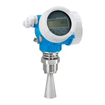
- Page 9 Micropilot FMR51, FMR52 FOUNDATION Fieldbus Product description Product description Product design 3.1.1 Micropilot FMR51 A0016818 1 Design of the Micropilot FMR51 (26 GHz) Electronics housing Process connection (Thread) Horn antenna Flange Antenna extension 3.1.2 Micropilot FMR52 A0016788 2...
- Page 10 Product description Micropilot FMR51, FMR52 FOUNDATION Fieldbus 3.1.3 Electronics housing A0012422 3 Design of the electronics housing Electronics compartment cover Display module Main electronics module Cable glands (1 or 2, depending on instrument version) Nameplate I/O electronics module Terminals (pluggable spring terminals)
- Page 11 Micropilot FMR51, FMR52 FOUNDATION Fieldbus Incoming acceptance and product identification Incoming acceptance and product identification Incoming acceptance DELIVERY NOTE 1 = 2 A0013696 A0016870 Is the order code on the delivery note (1) identical to the order code on the product sticker (2)?
- Page 12 Micropilot FMR51, FMR52 FOUNDATION Fieldbus A0013696 A0014037 Are the CD-ROMs (product documentation, operating tool) and documentation present? If required (see nameplate): Are the Safety Instructions (XA) present? If one of the conditions does not comply, contact your Endress+Hauser distributor. Endress+Hauser...
- Page 13 Micropilot FMR51, FMR52 FOUNDATION Fieldbus Incoming acceptance and product identification Product identification The following options are available for identification of the measuring device: • Nameplate specifications • Extended order code with breakdown of the device features on the delivery note •...
- Page 14 Incoming acceptance and product identification Micropilot FMR51, FMR52 FOUNDATION Fieldbus Only 33 digits of the extended order code can be indicated on the nameplate. If the extended order code exceeds 33 digits, the rest will not be shown. However, the...
- Page 15 Micropilot FMR51, FMR52 FOUNDATION Fieldbus Storage, Transport Storage, Transport Storage conditions • Permitted storage temperature: –40 to +80 °C (–40 to +176 °F) • Use the original packaging. Transport product to the measuring point NOTICE Housing or antenna horn may be damaged or break away.
- Page 16 Installation Micropilot FMR51, FMR52 FOUNDATION Fieldbus Installation Installation conditions 6.1.1 Mounting position • Recommended distance A from wall to outer edge of nozzle: ~ 1/6 of tank diameter. Nevertheless the device should not be installed closer than 15 cm (5.91 in) to the tank wall.
- Page 17 Micropilot FMR51, FMR52 FOUNDATION Fieldbus Installation 6.1.2 Vessel installations Avoid any installations (limit switches, temperature sensors, braces, vacuum rings, heating coils, baffles etc.) inside the signal beam. Take into account the beam angle ( 20). A0018944 Endress+Hauser...
- Page 18 (e.g. metallic pipes (1), ladders (2), grates (3), ...). Therefore, there should be no such interfering installations in the signal beam. Please contact Endress+Hauser for further information. A0017123 Endress+Hauser...
- Page 19 Micropilot FMR51, FMR52 FOUNDATION Fieldbus Installation 6.1.5 Optimization options • Antenna size The bigger the antenna, the smaller the beam angle α and the fewer interference echoes 20). • Mapping The measurement can be optimized by means of electronic suppression of interference echoes.
- Page 20 Installation Micropilot FMR51, FMR52 FOUNDATION Fieldbus 6.1.6 Beam angle A0016891 5 Relationship between beam angle α, distance D and beamwidth diameter W The beam angle is defined as the angle α where the energy density of the radar waves reaches half the value of the maximum energy density (3-dB-width).
- Page 21 Micropilot FMR51, FMR52 FOUNDATION Fieldbus Installation 9 m (30 ft) 2.85 m (9.4 ft) 1.58 m (5.2 ft) 12 m (39 ft) 3.80 m (12 ft) 2.1 m (6.9 ft) 15 m (49 ft) 4.75 m (16 ft) 2.63 m (8.6 ft) 20 m (66 ft) 6.34 m (21 ft)
- Page 22 Installation Micropilot FMR51, FMR52 FOUNDATION Fieldbus Measuring conditions • In case of boiling surfaces, bubbling or tendency for foaming use FMR53 or FMR54. Depending on its consistence, foam can either absorb microwaves or reflect them off the foam surface. Measurement is possible under certain conditions. For FMR50, FMR51 and FMR52, the additional option "Advanced dynamics"...
- Page 23 Micropilot FMR51, FMR52 FOUNDATION Fieldbus Installation 100% øD A0018872 Device A [mm (in)] B [m (ft)] C [mm (in)] H [m (ft)] FMR51 50(1.97) > 0.2 (0.7) 50 to 250 (1.97 to 9.84) > 0.3 (1.0) FMR52 200(7.87) Endress+Hauser...
- Page 24 Installation Micropilot FMR51, FMR52 FOUNDATION Fieldbus Installation in vessel (free space) 6.3.1 Horn antenna (FMR51) Alignment • Align the antenna vertically to the product surface. The maximum range may be reduced if the horn antenna is not vertically aligned. • A marking at the flange (somewhere between the flange holes) or the boss enables alignment of the antenna.
- Page 25 < 85 mm (3.35 in) < 115 mm (4.53 in) < 210 mm (8.27 in) < 280 mm (11.0 in) Please contact Endress+Hauser for applications with higher nozzle. Threaded connection • Tighten with the hexagonal nut only. • Tool : Hexagonal wrench 55 mm •...
- Page 26 Nozzle height an diameter for horn antenna, flush mount (FMR52) Spring washers Antenna size 50 mm (2 in) 80 mm (3 in) 44 mm (1.73 in) 75 mm (2.95 in) < 500 mm (19.7 in) < 500 mm (19.7 in) Please contact Endress+Hauser for applications with higher nozzle. Endress+Hauser...
- Page 27 Micropilot FMR51, FMR52 FOUNDATION Fieldbus Installation For flanges with PTFE cladding: Use spring washers (see figure) to compensate for the sagging of the cladding. It is recommended to tighten the the flange bolts periodically, depending on process temperature and pressure.
- Page 28 Installation Micropilot FMR51, FMR52 FOUNDATION Fieldbus Installation in stilling well A0016841 8 Installation in stilling well Marking for antenna alignment • For horn antenna: Align the marking towards the slots of the stilling well. • Measurements can be performed through an open full bore ball valve without any problems.
- Page 29 Micropilot FMR51, FMR52 FOUNDATION Fieldbus Installation 6.4.1 Recommendations for the stilling well • Metal (no enamel coating; plastic on request). • Constant diameter. • Diameter of stilling well not larger than antenna diameter. • Diameter difference between horn antenna and inner diameter of the stilling well as small as possible.
- Page 30 Installation Micropilot FMR51, FMR52 FOUNDATION Fieldbus 6.4.2 Examples for the construction of stilling wells 100% 100% mm (in) A0019009 Micropilot FMR50/FMR51: Horn 40mm(1½") Micropilot FMR50/FMR51/FMR52/FMR54: Horn 80mm(3") Stilling well with slots Full bore ball valve Marking for axial alignment Threaded connection e.g.
- Page 31 Micropilot FMR51, FMR52 FOUNDATION Fieldbus Installation Installation in bypass A0019446 9 Installation in bypass Marking for antenna alignment Tank connectors • Alighn the marker perpendicular (90°) to the tank connectors. • Measurements can be performed through an open full bore ball valve without any problems.
- Page 32 Installation Micropilot FMR51, FMR52 FOUNDATION Fieldbus 6.5.1 Recommendations for the bypass pipe • Metal (no plastic or enamel coating). • Constant diameter. • Select horn antenna as big as possible. For intermediate sizes (e.g. 95 mm (3.5 in)) select next larger antenna and adapt it mechanically (for horn antennas).
- Page 33 Micropilot FMR51, FMR52 FOUNDATION Fieldbus Installation 6.5.2 Example for the construction of a bypass 100% mm (in) A0019010 Micropilot FMR50/FMR51/FMR52/FMR54: Horn 80mm(3") Full bore ball valve Minimum distance to upper connection pipe: 400 mm (15,7 in) Marking for axial alignment e.g.
- Page 34 Installation Micropilot FMR51, FMR52 FOUNDATION Fieldbus Vessels with heat insulation A0019142 If process temperatures are high, the device must be included in normal tank insulation to prevent the electronics heating up as a result of heat radiation or convection. The insulation may not exceed beyond the neck of the housing.
- Page 35 Micropilot FMR51, FMR52 FOUNDATION Fieldbus Installation Turning the display module 3 mm A0013905 1. If present: Loosen the screw of the securing clamp of the electronics compartment cover using an Allen key and turn the clamp 90° conterclockwise. 2. Unscrew cover of the electronics compartment from the transmitter housing.
- Page 36 ≥60 °C (140 °F): use cable for temperature T +20 K. FOUNDATION Fieldbus Endress+Hauser recommends using twisted, shielded two-wire cables. For further information on the cable specifications, see Operating Instructions BA00013S "FOUNDATION Fieldbus Overview", FOUNDATION Fieldbus Guideline and IEC 61158-2 (MBP).
- Page 37 Micropilot FMR51, FMR52 FOUNDATION Fieldbus Electrical connection 7.1.2 Terminal assignment PROFIBUS PA / FOUNDATION Fieldbus A0011341 10 Terminal assignment PROFIBUS PA / FOUNDATION Fieldbus Without integrated overvoltage protection With integrated overvoltage protection Cable screen: Observe cable specifications Switch output (open collector): Terminals 3 and 4...
- Page 38 Electrical connection Micropilot FMR51, FMR52 FOUNDATION Fieldbus Connection examples for the switch output A0015909 A0015910 11 Connection of a relay 12 Connection of a digital input Pull-up resistor Suitable relays (examples): Digital input • Solid-state relay: Phoenix Contact OV-24DC/480AC/5 with mounting rail connector UMK-1 OM-R/AMS •...
- Page 39 Micropilot FMR51, FMR52 FOUNDATION Fieldbus Electrical connection 7.1.3 Device plug connectors For the versions with fieldbus plug connector (M12 or 7/8"), the signal line can be connected without opening the housing. Pin assignment of the M12 plug connector Meaning Signal +...
- Page 40 Electrical connection Micropilot FMR51, FMR52 FOUNDATION Fieldbus 7.1.4 Supply voltage PROFIBUS PA, FOUNDATION Fieldbus "Power supply; Output" "Approval" Terminal voltage E: 2-wire; FOUNDATION Fieldbus, switch output • Non-Ex 9 to 32 V G: 2-wire; PROFIBUS PA, switch output • Ex nA •...
- Page 41 < 1.5 pF Nominal arrest impulse voltage (⁸⁄₂₀ μs) 10 kA External overvoltage protection HAW562 or HAW569 from Endress+Hauser are suited as external overvoltage protection. For detailed information please refer to the following documents: • HAW562: TI01012K • HAW569: TI01013K...
- Page 42 Electrical connection Micropilot FMR51, FMR52 FOUNDATION Fieldbus Connecting the measuring device WARNING Explosion hazard! ‣ Comply with the relevant national standards. ‣ Observe the specifications in the Safety Instructions (XA). ‣ Only use the specified cable glands. ‣ Check whether the supply voltage matches the specifications on the nameplate.
- Page 43 Micropilot FMR51, FMR52 FOUNDATION Fieldbus Electrical connection Connect the cable in accordance with the terminal assignment ( 37). 8. When using screened cable: Connect the cable screen to the ground terminal. 9. Screw the cover onto the connection compartment.
- Page 44 Electrical connection Micropilot FMR51, FMR52 FOUNDATION Fieldbus Post-connection check Are cables or the device undamaged (visual inspection)? Do the cables comply with the requirements? Do the cables have adequate strain relief? Are all cable glands installed, firmly tightened and correctly sealed?
- Page 45 Micropilot FMR51, FMR52 FOUNDATION Fieldbus Operation options Operation options Overview 8.1.1 Local operation Order code for "Display; Operation", option C "SD02" Order code for "Display; Operation", option E "SD03" (in preparation) A0015546 A0015544 Operation with pushbuttons Operation with touch control 8.1.2...
- Page 46 Operation options Micropilot FMR51, FMR52 FOUNDATION Fieldbus 8.1.3 Remote operation Via FOUNDATION Fieldbus FF-HSE FF-H1 ENDRESS + HAUSER – FF-H1 A0017188 14 FOUNDATION Fieldbus system architecture with associated components FFblue Bluetooth modem Field Xpert SFX100 FieldCare NI-FF interface card...
- Page 47 Micropilot FMR51, FMR52 FOUNDATION Fieldbus Operation options Via service interface (CDI) A0014019 Service interface (CDI) of the measuring device (= Endress+Hauser Common Data Interface) Commubox FXA291 Computer with "FieldCare" operating tool Endress+Hauser...
- Page 48 Operation options Micropilot FMR51, FMR52 FOUNDATION Fieldbus Structure and function of the operating menu 8.2.1 Structure of the operating menu Menu Submenu / parameter Meaning Language Defines the operating language of the on-site display. Setup Parameter 1 When all these parameters have been...
- Page 49 Micropilot FMR51, FMR52 FOUNDATION Fieldbus Operation options 8.2.2 User roles and related access authorization The two user roles "Operator" and "Maintenance" have different write access to the parameters if a device-specific access code has been defined. This protects the device configuration via the local display from unauthorized access ( ...
- Page 50 Operation options Micropilot FMR51, FMR52 FOUNDATION Fieldbus 8.2.3 Write protection via access code Using the device-specific access code, the parameters for the measuring device configuration are write-protected and their values can no longer be changed via local operation. Define access code 1.
- Page 51 Micropilot FMR51, FMR52 FOUNDATION Fieldbus Operation options 8.2.6 Write protection via lock switch Unlike write protection via device-specific access code, this allows write access to the entire operating menu - other than the Contrast display parameter - to be locked.
- Page 52 Operation options Micropilot FMR51, FMR52 FOUNDATION Fieldbus 8.2.7 Enabling and disabling the keypad lock The keypad lock allows you disable access to the entire operating menu via local operation. Thus navigating through the operating menu or modifying the values of individual parameters is no longer possible.
- Page 53 Micropilot FMR51, FMR52 FOUNDATION Fieldbus Operation options Display and operating module 8.3.1 Display appearance User ABC_ DEFG HIJK LMNO PQRS TUVW A0012635 15 Appearance of the display and operation module for on-site operation Measured value display (1 value max. size) 1.1 Header containing tag and error symbol (if an error is active)
- Page 54 Operation options Micropilot FMR51, FMR52 FOUNDATION Fieldbus Display symbols for the submenus Symbol Meaning Display/operation Is displayed: • in the main menu next to the selection "Display/operation" A0011975 • in the header, if you are in the "Display/operation" menu Setup Is displayed: •...
- Page 55 Micropilot FMR51, FMR52 FOUNDATION Fieldbus Operation options Measured value symbols Symbol Meaning Measured values Level A0011995 Distance A0011996 Current output A0011998 Measured current A0011999 Terminal voltage A0012106 Temperature of the electronics or the sensor A0012104 Measuring channels Measuring channel 1...
- Page 56 Operation options Micropilot FMR51, FMR52 FOUNDATION Fieldbus 8.3.2 Operating elements Meaning Minus key For menu, submenu Moves the selection bar upwards in a picklist. A0013969 For text and numeric editor In the input mask, moves the selection bar to the left (backwards).
- Page 57 Micropilot FMR51, FMR52 FOUNDATION Fieldbus Operation options 8.3.3 Entering numbers and text Numeric editor Text editor A0013941 A0013999 Editing view Display area of the entered values Input mask Operating elements Input mask The following input symbols are available in the input mask of the numeric and text editor:...
- Page 58 Operation options Micropilot FMR51, FMR52 FOUNDATION Fieldbus Confirms selection. A0013985 Switches to the selection of the correction tools. A0013987 Exits the input without applying the changes. A0013986 Clears all entered characters. A0014040 Operating symbols in the numeric editor A0016621 A0013985 A0013986 Confirms selection.
- Page 59 Micropilot FMR51, FMR52 FOUNDATION Fieldbus Operation options 8.3.4 Envelope curve on the display and operating module In order to assess the measuring signal, the envelope curve and - if a mapping has been recorded - the mapping curve can be displayed:...
- Page 60 Integration into a FOUNDATION Fieldbus network Micropilot FMR51, FMR52 FOUNDATION Fieldbus Integration into a FOUNDATION Fieldbus network Device Description (DD) You require the following to configure a device and integrate it into an FF network: • An FF configuration program •...
- Page 61 Micropilot FMR51, FMR52 FOUNDATION Fieldbus Integration into a FOUNDATION Fieldbus network – EH_Micropilot_xxxxxxxxxx – RESOURCE_xxxxxxxxxxx (RB2) SETUP_ xxxxxxxxxxx (TRDSUP) ADV_SETUP_ xxxxxxxxxxx (TRDASUP) DISPLAY_ xxxxxxxxxxx (TRDDISP) DIAGNOSTIC_ xxxxxxxxxxx (TRDDIAG) EXPERT_CONFIG_ xxxxxxxxxxx (TRDEXP) EXPERT_INFO_ xxxxxxxxxxx (TRDEXPIN) SERVICE_SENSOR_ xxxxxxxxxxx (TRDSRVSB) SERVICE_INFO_ xxxxxxxxxxx (TRDSRVIF)
- Page 62 Endress+Hauser Guideline BA00062S. The guideline provides an overview of the standard function blocks that are described in FOUNDATION Fieldbus Specifications FF 890 - 894. It is designed to help operators use the blocks implemented in the Endress+Hauser field devices. Endress+Hauser...
- Page 63 Micropilot FMR51, FMR52 FOUNDATION Fieldbus Integration into a FOUNDATION Fieldbus network 9.4.2 Block configuration when device is delivered Device_01 4841.000 DIAGNOSTIC RESOURCE DISPLAY DATA_TRANSFER SETUP ANALOG_INPUT_1 ADV_SETUP ANALOG_INPUT_2 EXPERT_CONFIG EXPERT_INFO SERVICE_SENSOR SERVICE_INFO ARITHMETIC SIGNAL_CHAR INPUT_SELECTOR INTEGRATOR ANALOG_ALARM A0017217 17...
- Page 64 Integration into a FOUNDATION Fieldbus network Micropilot FMR51, FMR52 FOUNDATION Fieldbus 9.6.1 Setup Transducer Block Name Label Index Data type Size (Bytes) Storage Class Write access MODE_BLK operating_mode Operating mode ENUM16 Static Maintenance distance_unit Distance unit ENUM16 Static Maintenance tank_type...
-
Page 65: Table Of Contents
Micropilot FMR51, FMR52 FOUNDATION Fieldbus Integration into a FOUNDATION Fieldbus network Name Label Index Data type Size (Bytes) Storage Class Write access MODE_BLK calculated_dc_value_ee Calculated DC value FLOAT Dynamic Production AUTO liquid_filling_speed_range Max. filling speed liquid ENUM16 Static Maintenance liquid_draining_speed_ran Max. - Page 66 Integration into a FOUNDATION Fieldbus network Micropilot FMR51, FMR52 FOUNDATION Fieldbus Name Label Index Data type Size (Bytes) Storage Class Write access MODE_BLK access_code_for_display Enter access code UINT16 Static Operator AUTO define_access_code Freigabecode definieren UINT16 Static Maintenance AUTO language Language...
- Page 67 Micropilot FMR51, FMR52 FOUNDATION Fieldbus Integration into a FOUNDATION Fieldbus network Name Label Index Data type Size (Bytes) Storage Class Write access MODE_BLK diag_4_timestamp Timestamp STRING Dynamic diagnostics_5 Diagnostics 5 UINT32 Dynamic diag_5_timestamp Timestamp STRING Dynamic filter_options Filter options ENUM8...
- Page 68 Integration into a FOUNDATION Fieldbus network Micropilot FMR51, FMR52 FOUNDATION Fieldbus Name Label Index Data type Size (Bytes) Storage Class Write access MODE_BLK level_limit_mode Level limit mode ENUM16 Static Maintenance OOS level_high_limit High limit FLOAT Static Maintenance OOS level_low_limit Low limit...
- Page 69 Micropilot FMR51, FMR52 FOUNDATION Fieldbus Integration into a FOUNDATION Fieldbus network 9.6.6 Expert Information Transducer Block The parameters of the Expert Information Transducer Block are described in GP01017F: "Micropilot FMR5x - Description of Device Parameters - FOUNDATION Fieldbus" Name Label...
- Page 70 Integration into a FOUNDATION Fieldbus network Micropilot FMR51, FMR52 FOUNDATION Fieldbus 9.6.8 Service Information Transducer Block The parameters of the Service Information Transducer Block can only be operated by authorized Endress+Hauser service personnel. 9.6.9 Advanced Diagnostics Transducer Block The parameters of the Advanced Diagnostics Transducer Block are described in GP01017F: "Micropilot FMR5x - Description of Device Parameters - FOUNDATION...
- Page 71 Micropilot FMR51, FMR52 FOUNDATION Fieldbus Integration into a FOUNDATION Fieldbus network Methods The FOUNDATION Fieldbus Specification includes the use of methods to make device operation easier. A method is a sequence of interactive steps to be carried out in the specified order so as to configure certain device functions.
- Page 72 Commissioning (via operating menu) Micropilot FMR51, FMR52 FOUNDATION Fieldbus Commissioning (via operating menu) 10.1 Installation and function check Make sure that all final checks have been completed before you start up your measuring point: • Checklist "Post-installation check" ( 35) •...
- Page 73 Micropilot FMR51, FMR52 FOUNDATION Fieldbus Commissioning (via operating menu) 10.3 Configuration of a level measurement 100% A0016933 1. Setup → Device tag Enter device tag. 2. Setup → Distance unit( 111) Select distance unit. 3. Setup → Tank type( ...
- Page 74 Commissioning (via operating menu) Micropilot FMR51, FMR52 FOUNDATION Fieldbus The response time of the device is preset by the Tank type parameter. An enhanced setting is possible in the Advanced setup submenu. Endress+Hauser...
- Page 75 Micropilot FMR51, FMR52 FOUNDATION Fieldbus Commissioning (via operating menu) 10.4 Configurationof the on-site display 10.4.1 Factory settings of the on-site display Parameter Factory setting Format display 1 value, max. size Value 1 display Levele linearized Value 2 display None Value 3 display...
- Page 76 Commissioning (block-based operation) Micropilot FMR51, FMR52 FOUNDATION Fieldbus Commissioning (block-based operation) 11.1 Function check Carry out a post-installation and a post-connection check as per the checklist before commissioning the device: • "Post-installation check" checklist ( 35) • "Post-connection check" checklist ( ...
- Page 77 Micropilot FMR51, FMR52 FOUNDATION Fieldbus Commissioning (block-based operation) 11.2.4 Configuring the Analog Input Blocks The device has 2 permanently instanced Analog Input Blocks that can be assigned as required to the various process variables. If required, up to 5 Analog Input Blocks can be instanced through the FOUNDATION Fieldbus configuration tool.
- Page 78 Commissioning (block-based operation) Micropilot FMR51, FMR52 FOUNDATION Fieldbus XD_SCALE OUT_SCALE EU_100 EU_0 EU_100 EU_0 OUT_VALUE A0017338 19 Scaling of the measured value in an AI Block • If you have selected the Direct mode for the L_TYPE parameter, you cannot change the values and units for XD_SCALE and OUT_SCALE.
- Page 79 Micropilot FMR51, FMR52 FOUNDATION Fieldbus Commissioning (block-based operation) 11.5 Configuration of a level measurement The Setup method can also be used to configure the measurement. It is called up via the SETUP (TRDSUP) Transducer Block. 100% A0016933 R = Reference point of the measurement E = Empty calibration (= Zero point)
- Page 80 Commissioning (block-based operation) Micropilot FMR51, FMR52 FOUNDATION Fieldbus Step Block Parameter Action Description SETUP (TRDSUP) Level (level) Displays the measured level L. 114) SETUP (TRDSUP) Distance Displays the distance D between the 114) (filtered_dist_val) reference point R and the level L.
- Page 81 Micropilot FMR51, FMR52 FOUNDATION Fieldbus Commissioning (block-based operation) Parameter: Configuration management (configuration_management) Functions of the parameter options Options Description 33097: Execute backup A backup copy of the current device configuration in the HistoROM is saved to the display module of the device. The backup copy comprises the transmitter data of the device.
- Page 82 Commissioning (block-based operation) Micropilot FMR51, FMR52 FOUNDATION Fieldbus 11.8 Configuration of the event behavior according to the FOUNDATION Fieldbus specification FF912 The device complies with the FOUNDATION Fieldbus specification FF912. This has - among other things - the following consequences: •...
- Page 83 Micropilot FMR51, FMR52 FOUNDATION Fieldbus Commissioning (block-based operation) 11.8.1 Groups of events The diagnostic messages are classified into 16 groups according to the source and severity of the respective event. A default diagnostic category is allocated to each group. Each group is also represented by one bit of the allocation parameters.
- Page 84 Commissioning (block-based operation) Micropilot FMR51, FMR52 FOUNDATION Fieldbus Severity of the Default diagnostic category Source of the Events within the group event event Configuration • S442: Frequency output • S443: Pulse output Process • S801: Energy too low • S825: Operating temperature •...
- Page 85 Micropilot FMR51, FMR52 FOUNDATION Fieldbus Commissioning (block-based operation) 11.8.2 Allocation parameters The allocation of event categories to the event groups is controlled by the allocation parameters. They reside in the RESOURCE (RB2) block: • FD_FAIL_MAP: for the Failure (F) event category •...
- Page 86 Commissioning (block-based operation) Micropilot FMR51, FMR52 FOUNDATION Fieldbus A0017618 Use the FieldCare navigation window to navigate to the the following screen: Expert → Communication → Field diagnostics → Alarm detection enable. A0017621 20 Default state of the "Fail Map" and "Check Map" columns Look for the Configuration Highest Severity group in the Fail Map column and deactivate the associated checkbox (A).
- Page 87 Micropilot FMR51, FMR52 FOUNDATION Fieldbus Commissioning (block-based operation) A0017615 21 Changed state of the "Fail Map" and "Check Map" columns Make sure that for each group the corresponding bit is set to 1 in at least one of the allocation parameters.
- Page 88 Commissioning (block-based operation) Micropilot FMR51, FMR52 FOUNDATION Fieldbus 11.8.3 Configurable area An event category can be individually defined for the following parameters - irrespective of the group of events they belong to by default. • F941: Echo lost • S942: In safety distance •...
- Page 89 Micropilot FMR51, FMR52 FOUNDATION Fieldbus Commissioning (block-based operation) A0017620 Got to the Offspec Map column and activate the checkbox of the respective bit (in the example: Configurable Area Bit 1). Confirm the selection by pressing the Enter key. A change of the error category of In safety distance does not affect an error which is already present.
- Page 90 Commissioning (block-based operation) Micropilot FMR51, FMR52 FOUNDATION Fieldbus • Via locking switch (hardware locking) ( 51) • Via operating menu (software locking) ( 50) • Via block operation: – Block: DISPLAY (TRDDISP); parameter: Define access code (define_access_code) – Block: EXPERT_CONFIG (TRDEXP); parameter: Enter access code...
- Page 91 Micropilot FMR51, FMR52 FOUNDATION Fieldbus Diagnostics and troubleshooting Diagnostics and troubleshooting 12.1 General trouble shooting 12.1.1 General errors Error Possible cause Remedial action Device does not respond. Supply voltage not connected. Connect the correct voltage. The cables do not contact the Ensure electrical contact between the terminals properly.
- Page 92 Diagnostics and troubleshooting Micropilot FMR51, FMR52 FOUNDATION Fieldbus Error Possible cause Remdy • Carry out tank mapping (Setup → If the surface is not calm (e.g. Signal is weakened by the rough Mapping). filling, emptying, agitator surface - the interference echoes are •...
- Page 93 Micropilot FMR51, FMR52 FOUNDATION Fieldbus Diagnostics and troubleshooting Status signals "Failure" A device error is present. The measured value is no longer valid. A0013956 "Function check" The device is in service mode (e.g. during a simulation). A0013959 "Out of specification"...
- Page 94 Diagnostics and troubleshooting Micropilot FMR51, FMR52 FOUNDATION Fieldbus 12.2.2 Calling up remedial measures X X X X X X X X X X X X X X 20.50 S801 Supply voltage Menu Diagnostic list Diagnostics 1 S801 Supply voltage Diagnostics 2...
- Page 95 Micropilot FMR51, FMR52 FOUNDATION Fieldbus Diagnostics and troubleshooting Calling up remedial measures 1. Navigate to the "Diagnostics" menu. In the "Actual diagnostics" parameter, the diagnostic event is shown with event text. 2. On the right in the display range, hover the cursor over the "Actual diagnostics"...
- Page 96 Diagnostics and troubleshooting Micropilot FMR51, FMR52 FOUNDATION Fieldbus 12.6.2 Electronic failures Diagnostic event Maintenance instructions Error behavior Code Description F242 Software incompatible 1. Check software Alarm 2. Flash or change main electronics module F252 Modules incompatible 1. Check electronic odules Alarm 2.
- Page 97 Micropilot FMR51, FMR52 FOUNDATION Fieldbus Diagnostics and troubleshooting Diagnostic event Maintenance instructions Error behavior Code Description C494 Simulation switch Deactivat simulation switch output Warning output C585 Simulation distance Deactivate simulation Warning C586 Record map Recording of mapping: please wait Warning 12.6.4...
- Page 98 Diagnostics and troubleshooting Micropilot FMR51, FMR52 FOUNDATION Fieldbus In addition to the operation time of its occurrence, each event is also assigned a symbol that indicates whether the event has occurred or is ended: • Diagnostic event – : Event has occurred –...
- Page 99 Micropilot FMR51, FMR52 FOUNDATION Fieldbus Diagnostics and troubleshooting Information Event text event I1187 Settings downloaded with display I1188 Display data cleared I1189 Backup compared I1264 Safety sequence aborted I1335 Firmware changed I1397 Fieldbus: access status changed I1398 CDI: access status changed 12.8...
- Page 100 Maintenance Micropilot FMR51, FMR52 FOUNDATION Fieldbus Maintenance The measuring device requires no special maintenance. 13.1 Exterior cleaning When exterior-cleaning the device, always use cleaning agents that do not attack the surface of the hosuing and the seals. 13.2 Replacing seals The process seals of the sensors (at the process connection) must be replaced periodically, particularly if molded seals (aseptic construction) are used.
- Page 101 14.1.1 Repair concept The Endress+Hauser repair concept assumes that the devices have a modular design and that repairs can be done by the Endress+Hauser service or specially trained customers. Spare parts are contained in suitable kits. They contain the related replacement instructions.
- Page 102 The measuring device must be returned if repairs or a factory calibration are required, or if the wrong measuring device has been ordered or delivered. According to legal regulations, Endress+Hauser, as an ISO-certified company, is required to follow certain procedures when handling returned products that are in contact with medium.
- Page 103 Micropilot FMR51, FMR52 FOUNDATION Fieldbus Accessories Accessories 15.1 Device-specific accessories Accessory Description Weather protection cover mm (in) A0015466 298.5 (11.8) 273.8 (10.8) 164 (6.46) 255.1 (10) mm (in) A0015472 37.8 mm (1.49 in) 54 mm (2.13 in) The weather protection cover can be ordered together with the device (product structure, feature 620 "Accessory Enclosed", option PB "Weather Protection Cover").
- Page 104 Accessories Micropilot FMR51, FMR52 FOUNDATION Fieldbus Accessory Description Remote display FHX50 A0019128 • Material: – Plastics PBT – 316L (in preparation) • Suitable for the display modules: – SD02 (push buttons) – SD03 (touch control) (in preparation) • Connection cable: –...
- Page 105 Avoid electrostatic charging of the horn protection. 15.2 Communication-specific accessories Accessory Description Commubox FXA291 Connects Endress+Hauser field devices with CDI interface (= Endress+Hauser Common Data Interface) to the USB interface of a computer. For details refer to Technical Information TI00405C Accessory Description Field Xpert SFX100...
- Page 106 Accessories Micropilot FMR51, FMR52 FOUNDATION Fieldbus 15.4 System components Accessory Description Graphic Data Manager The graphic data manager Memograph M provides information on all the relevant Memograph M process variables. Measured values are recorded correctly, limit values are monitored and measuring points analyzed. The data are stored in the 256 MB internal memory and also on an SD card or USB stick.
- Page 107 Micropilot FMR51, FMR52 FOUNDATION Fieldbus Overview of the operating menu Overview of the operating menu Language 111) Setup → Device tag 111) Distance unit 111) Tank type 112) Tube diameter 112) Medium group 112) Empty calibration ...
- Page 108 Overview of the operating menu Micropilot FMR51, FMR52 FOUNDATION Fieldbus Diameter 128) Intermediate height 128) Table mode 129) Table number 129) Level 130) Customer value 130) Activate table 130) Setup → Advanced setup →...
- Page 109 Micropilot FMR51, FMR52 FOUNDATION Fieldbus Overview of the operating menu Backlight 143) Contrast display 144) Setup → Advanced setup → Configuration backup display Operating time 145) → Last backup 145) Configuration management 145) Camparison result ...
- Page 110 Overview of the operating menu Micropilot FMR51, FMR52 FOUNDATION Fieldbus Diagnostics → Analog inputs → Analog input N → Block tag 157) Channel 157) Status 157) Value 157) Units index 158) Diagnostics → Data logging →...
- Page 111 Micropilot FMR51, FMR52 FOUNDATION Fieldbus Description of device parameters Description of device parameters • : Marks the navigation path to the parameter via the display and operating module. • : Marks the navigation path to the parameter via an operating tool (e.g.
- Page 112 Description of device parameters Micropilot FMR51, FMR52 FOUNDATION Fieldbus Tank type Navigation Setup Tank type Description Defines the tank type Options • Process vessel with agitator • Process vessel standard • Storage vessel • Bypass / pipe • Open channel •...
- Page 113 Micropilot FMR51, FMR52 FOUNDATION Fieldbus Description of device parameters Additional information If required, smaller DC values can be entered into "Expert Sensor Medium Medim property". This, however, may reduce the measuring range. Empty calibration Navigation Setup Empty calibration Description Distance process connection to min. level...
- Page 114 Description of device parameters Micropilot FMR51, FMR52 FOUNDATION Fieldbus Additional information The full calibration F is the distance between the minimum level (0%) and the maximum level (100%). 100% A0019487 Level Navigation Setup Level Description Displays the measured level L (before...
- Page 115 Micropilot FMR51, FMR52 FOUNDATION Fieldbus Description of device parameters Description Displays the measured distance D from the reference point (lower edge of the flange or threaded connection) to the level. A0019483 Additional information The value is displayed in the selected "Level unit" ( ...
- Page 116 Description of device parameters Micropilot FMR51, FMR52 FOUNDATION Fieldbus 17.1.1 "Mapping" sequence Overview On the local display In the Mapping submenu two parameters are displayed on the local display at the same time. The upper parameter can be edited. The lower parameter is displayed for reference purposes only.
- Page 117 Micropilot FMR51, FMR52 FOUNDATION Fieldbus Description of device parameters In the operating tool (e.g. FieldCare) Parameter Meaning Description Distance Displays the currently measured distance 114) Confirm distance Confirm whether the displayed distance 117) matches the actual distance. Present mapping Indicates the distance up to which a mapping ...
- Page 118 Description of device parameters Micropilot FMR51, FMR52 FOUNDATION Fieldbus Additonal information Check whether the displayed distance matches the actual distance. Depending on the selection, the device automatically determines the range over which the mapping will be recorded. For reference purposes the measured distance is displayed together with this parameter.
- Page 119 Micropilot FMR51, FMR52 FOUNDATION Fieldbus Description of device parameters Input range 0.1 m (0.33 ft) ... Tanks /silo height Parameter: "Expert Sensor Level Tank/silo height" Factory setting 1 m (3.3 ft) Additional information This parameter defines up to which distance the new mapping is to be recorded.
- Page 120 Description of device parameters Micropilot FMR51, FMR52 FOUNDATION Fieldbus 17.1.2 The "Analog inputs → Analog input N" submenus There is an "Analog inputs N" submenu for every AI block of the device. The AI block is used to configure the measured value transmission to the bus.
- Page 121 If no key is pressed for 10 minutes, or the user goes from the navigation and editing mode back to the measured value display mode, the device automatically locks the write- protected parameters after another 60 s . Please contact your Endress+Hauser Sales Center if you lose your access code Endress+Hauser...
- Page 122 Description of device parameters Micropilot FMR51, FMR52 FOUNDATION Fieldbus The "Level" submenu Medium type Navigation Setup Advanced Setup Level Medium type Description Indication of the medium type Display options • Liquid • Solid Factory setting Liquid Medium property Navigation Setup...
-
Page 123: Advanced_Process_Conditio
Micropilot FMR51, FMR52 FOUNDATION Fieldbus Description of device parameters Options • Slow < 1cm (0.4in)/min • Medium < 10cm (4in)/min • Standard < 1m (40in)/min • Fast < 2m (80in) /min • Very fast > 2m (80in) /min • No filter / test Factory setting Standard <... -
Page 124: Level_Unit
Description of device parameters Micropilot FMR51, FMR52 FOUNDATION Fieldbus Level unit Navigation Setup Advanced setup Level Level unit Description Defines the level unit Options • % • m • mm • ft • in Factory setting Additional information The level unit may differ from the distance unit as defined in the Distance unit parameter ... -
Page 125: Level_Correction
Micropilot FMR51, FMR52 FOUNDATION Fieldbus Description of device parameters Level correction Navigation Setup Advanced setup Level Level correction Description Defines a level correction Input range Depending on the selected level unit: • -100,0 to 100,0 % • -200,0 to +200,0 m •... -
Page 126: Linearization_Type
Description of device parameters Micropilot FMR51, FMR52 FOUNDATION Fieldbus The "Linearization" submenu Linearization type Navigation Setup Advanced setup Linearization Linearization type Description Defines the type of linearization Options • None The level is transmitted without 100% linearization. • Linear (A) •... -
Page 127: Free_Text
Micropilot FMR51, FMR52 FOUNDATION Fieldbus Description of device parameters Description Defines the unit of the linearized value. Options • Free text • t • lb • ton • kg • impGal • UsGal • ft • cm • dm • m •... -
Page 128: Intermediate_Height
Description of device parameters Micropilot FMR51, FMR52 FOUNDATION Fieldbus Input range -50000 ... +50000 Factory setting Diameter Navigation Setup Advanced setup Linearization Diameter Prerequisite Only visible if one of the following linearization types has been selected: • Horizontal cylinder • Sphere... -
Page 129: Table_Number
Micropilot FMR51, FMR52 FOUNDATION Fieldbus Description of device parameters Table mode Navigation Setup Advanced setup Linearization Table mode Prerequisite Only visible if the "Table" linearization type has been selected. Description Defines the method used to enter linearization points into the table. -
Page 130: Activate_Table
Description of device parameters Micropilot FMR51, FMR52 FOUNDATION Fieldbus Level Navigation Setup Advanced setup Linearization Level Prerequisite Only visible if the "Table" linearization type has been selected. Description Definition or display of the (unlinearized) level of the respective linearization point. -
Page 131: Output_Echo_Lost
Micropilot FMR51, FMR52 FOUNDATION Fieldbus Description of device parameters The "Safety settings" submenu Output echo lost Navigation Setup Advanced setup Safety settings Output echo lost Description Defines the output signal in the case of a lost echo. Options • Last valid value The last valid value is kept in the case of a lost echo. - Page 132 Description of device parameters Micropilot FMR51, FMR52 FOUNDATION Fieldbus Description Defines the slope of the ramp in the case of a lost echo. 100% A0013269 Delay echo lost Ramp echo lost (positive value) Ramp echo lost (negative value) Input range...
-
Page 133: Switch_Output_Function
Micropilot FMR51, FMR52 FOUNDATION Fieldbus Description of device parameters "Switch output" submenu Switch output function Navigation Setup Advanced setup Switch output Switch output function Description Select function for switch output Options • Off The output is always open (not conductive). -
Page 134: Switch_On_Value
Description of device parameters Micropilot FMR51, FMR52 FOUNDATION Fieldbus Description Defines the variable to be checked for limit transgression and allocates it to the switch output. Options • Off • Level linearized • Distance • Terminal voltage • Electronic temperature •... -
Page 135: Switch_On_Delay
Micropilot FMR51, FMR52 FOUNDATION Fieldbus Description of device parameters Additional information The switching behavior depends on the relative position of the two switch points. Switch-on point > Switch-off point: The output is closed if the measured value exceeds the switch-on point. -
Page 136: Switch_Off_Delay
Description of device parameters Micropilot FMR51, FMR52 FOUNDATION Fieldbus Prerequisite Only visible for Switch output function = Limit and Assign limit ≠ Off. Description Defines the delay for the switching on of the output. Input range 0 to 100 s... -
Page 137: Invert_Output_Signal
Micropilot FMR51, FMR52 FOUNDATION Fieldbus Description of device parameters Invert output signal Navigation Setup Advanced setup Switch output Invert output signal Description Allows to invert the behavior of the switch output. Options • No The behavior of the switch output is as described above. - Page 138 Description of device parameters Micropilot FMR51, FMR52 FOUNDATION Fieldbus The "Display" submenu For operating tools: The Display submenu is only visible if a display module is connected to the device. Language 111) Format display Navigation Setup Advanced Setup Display...
- Page 139 Micropilot FMR51, FMR52 FOUNDATION Fieldbus Description of device parameters Additional information 1 value, max. size 4841.000  A0019963 1 bargraph + 1 value  93.5 %  159.0 A0019964 2 values  93.5  159.0 A0019965 1 value large + 2 values Â...
- Page 140 Description of device parameters Micropilot FMR51, FMR52 FOUNDATION Fieldbus Value 1 display Value 2 display Value 3 display Value 4 display Navigation Setup Advanced setup Display Value 1/2/3/4 display Description Select the measured value that is schown on the local display.
- Page 141 Micropilot FMR51, FMR52 FOUNDATION Fieldbus Description of device parameters Display interval Navigation Setup Advanced Setup Display Display interval Description Set time measured values are shown on display if display alternates between values. Input range 1 to 10 s Facotry setting...
- Page 142 Description of device parameters Micropilot FMR51, FMR52 FOUNDATION Fieldbus Additional information XXXXXXXXX A0013375 Position of the header text on the display Device tag Free text Is defined in the Header text parameter ( 142). Header text Navigation Setup Advanced setup...
- Page 143 Micropilot FMR51, FMR52 FOUNDATION Fieldbus Description of device parameters Number format Navigation Setup Advanced setup Display Number format Description Choose number format for the display Options • Decimal • ft-in-1/16" (Only valid for distance units) Factory setting Decimal Decimal places menu...
- Page 144 Description of device parameters Micropilot FMR51, FMR52 FOUNDATION Fieldbus Additional information Irrespective of the setting in this parameter the backlight may be automatically switched off by the device if the supply voltage is too low. Contrast display Navigation Display/operation Contrast display Description Adjust local display contrast setting to ambient conditions.
- Page 145 Micropilot FMR51, FMR52 FOUNDATION Fieldbus Description of device parameters The "Configuration backup display" submenu The Configuration backup display submenu is only visible if a display module is connected to the device. The configuration of the device can be saved to the display module at a certain point of time (backup).
- Page 146 Description of device parameters Micropilot FMR51, FMR52 FOUNDATION Fieldbus Options • Cancel No action is executed and the user exits the parameter. • Execute backup A backup copy of the current device configuration in the HistoROM (built-in in the device) is saved to the display module of the device. The backup copy comprises the transmitter and sensor data of the device.
- Page 147 Micropilot FMR51, FMR52 FOUNDATION Fieldbus Description of device parameters Display options • Settings identical The current device configuration of the HistoROM is identical to the backup copy in the display module. • Settings not identical The current device configuration of the HistoROM is not identical to the backup copy in the display module.
- Page 148 Enter access code parameter 121). Please contact your Endress+Hauser Sales Center if you lose your access code. For display operation: The new access code is only valid after it has been confirmed in the Confirm access code parameter and after the user has returned to the main screen (measured value display).
- Page 149 Micropilot FMR51, FMR52 FOUNDATION Fieldbus Description of device parameters Further parameters Restart Navigation Setup Advanced Setup Administration Restart Description Use this function to reset the device configuration - either entirely or in part - to a defined state. Options • Uninitialized •...
- Page 150 Description of device parameters Micropilot FMR51, FMR52 FOUNDATION Fieldbus 17.2 The "Diagnostics" menu Actual diagnostics Navigation Diagnostics Actual diagnos. Description Use this function to display the current diagnostics message. If two or more messages occur simultaneously, the message with the highest priority is shown on the display.
- Page 151 Micropilot FMR51, FMR52 FOUNDATION Fieldbus Description of device parameters 17.2.1 "Diagnsotics list" submenu Up to 5 diagnostics messages currently pending are displayed in this submenu. If more than 5 messages are pending, the messages with the highest priority are shown on the display.
- Page 152 Description of device parameters Micropilot FMR51, FMR52 FOUNDATION Fieldbus 17.2.2 The "Event logbook" submenu Filter options Navigation Diagnostics Event logbook Filter options Description Use this function to select the category (status signal) whose event messages are displayed in the events list.
- Page 153 Micropilot FMR51, FMR52 FOUNDATION Fieldbus Description of device parameters Additional information User interface Example 1 for display format: I 1091 24d12h13m00s Configuration modified Example 2 for display format: S441 01d4h12min30s Current output 1 HistoROM A HistoROM is a "non-volatile" device memory in the form of an EEPROM.
- Page 154 Use this function to view the serial number of the device. It can also be found on the nameplate. Uses of the serial number • To identify the device quickly, e.g. when contacting Endress+Hauser. • To obtain specific information on the device using the Device Viewer: www.endress.com/deviceviewer Display Max.
- Page 155 Uses of the order code • To order an identical spare device. • To identify the device quickly and easily, e.g. when contacting Endress+Hauser. Extended order code 1 Extended order code 2...
- Page 156 Description of device parameters Micropilot FMR51, FMR52 FOUNDATION Fieldbus 17.2.4 "Measured value" submenu Distance 114) Level linearized Navigation Diagnostics Measured val. Level linearized Description Displays the linearized level. Additional information The level is displayed in the Unit linearized( 126).
- Page 157 Micropilot FMR51, FMR52 FOUNDATION Fieldbus Description of device parameters 17.2.5 The "Analog inputs → Analog input N" submenus There is an "Analog inputs N" submenu for every AI block of the device. The AI block is used to configure the measured value transmission to the bus.
- Page 158 Description of device parameters Micropilot FMR51, FMR52 FOUNDATION Fieldbus Units index Navigation Diagnostics Analog inputs Analog input N Units index Description Indicates the unit of the output value. Endress+Hauser...
- Page 159 Micropilot FMR51, FMR52 FOUNDATION Fieldbus Description of device parameters 17.2.6 "Data logging" submenu This submenu is only available if the advanced functionality of the HistoROM has been activated in the device. Das Menü wird nur angezeigt, wenn im Gerät die erweiterter Funktion des HistoROM freigeschaltet ist.
- Page 160 Description of device parameters Micropilot FMR51, FMR52 FOUNDATION Fieldbus Description Definition of the logging interval t for data logging. This defines the interval between the individual data points in the data log, and thus the maximum loggable process time T •...
- Page 161 Micropilot FMR51, FMR52 FOUNDATION Fieldbus Description of device parameters Description Use this function to view the measured value trend for the logging channel in the form of a chart. A0013859 • x-axis: depending on the number of channels selected displays 250 to 1000 measured values of a process variable.
- Page 162 Description of device parameters Micropilot FMR51, FMR52 FOUNDATION Fieldbus 17.2.7 "Simulation" submenu Assignment of measured variable Navigation Diagnostics Simulation Assign. meas. var. Description Use this function to select a process variable for the simulation process that is activated. The display alternates between the measured value and a diagnostics message of the "function check"...
- Page 163 Micropilot FMR51, FMR52 FOUNDATION Fieldbus Description of device parameters Additional information The switch output can also be simulated by selecting the On or Off option in Setup → Advanced setup → Switch output → Switch output function. Switch status Navigation...
- Page 164 Description of device parameters Micropilot FMR51, FMR52 FOUNDATION Fieldbus 17.2.8 The "Device check" submenu Start device check Navigation Diagnostics Device check Start device check Description Start of a device check. Options • No No device check is performed. • Yes A device check is performed.
- Page 165 Micropilot FMR51, FMR52 FOUNDATION Fieldbus Description of device parameters Navigation Diagnostics Device check Level signal Prerequisite Only visible if a device check has been performed. Description Displays the result of the device check for the level signal. Display options • Check not done •...
- Page 166 *71219971* 71219971 www.addresses.endress.com...
Need help?
Do you have a question about the Micropilot FMR51 and is the answer not in the manual?
Questions and answers