Table of Contents
Advertisement
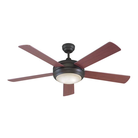
Installation Guide
For Models:
E-TIT52ABZ5LKRC
E-TIT52SCH5LKRC
E-TIT52WW5LKRC
E4009218
net weight of fan: 21.54 lb (9.77 kg)
READ THESE INSTRUCTIONS AND
AND SAVE THEM FOR FUTURE USE
Table of Contents:
Safety Tips. pg. 1
Unpacking Your Fan. pg. 2
Parts Inventory. pg. 2
Installation Preparation. pg. 3
Hanging Bracket Installation. pg. 3
Fan Assembly. pgs. 4 - 5
Wiring. pg. 6
Canopy Assembly. pg. 6
Light Kit Assembly. pg. 7
Remote Control Operation. pg. 8
Testing Your Fan. pg. 8
Troubleshooting. pg. 9
Warranty. pg. 9
Parts Replacement. pg. 9
PRINTED IN CHINA
Advertisement
Table of Contents

Related Manuals for Litex E-TIT52ABZ5LKRC


Summary of Contents for Litex E-TIT52ABZ5LKRC
-
Page 1: Table Of Contents
READ THESE INSTRUCTIONS AND AND SAVE THEM FOR FUTURE USE Installation Guide For Models: E-TIT52ABZ5LKRC E-TIT52SCH5LKRC E-TIT52WW5LKRC Table of Contents: Safety Tips. pg. 1 Unpacking Your Fan. pg. 2 Parts Inventory. pg. 2 Installation Preparation. pg. 3 Hanging Bracket Installation. pg. 3 Fan Assembly. -
Page 2: Safety Tips
SAFETY TIPS. WARNING: To reduce the risk of electrical shock, turn off the electricity to the fan at the main fuse box or circuit panel before you begin the fan installation or before servicing the fan or installing accessories. READ ALL INSTRUCTIONS AND SAFETY INFORMATION CAREFULLY BEFORE INSTALLING YOUR FAN AND SAVE THESE INSTRUCTIONS. -
Page 3: Unpacking Your Fan
1. Unpacking Your Fan. Carefully open the packaging. Remove items from Styrofoam inserts. Remove motor housing and place on carpet or Styrofoam to avoid damage to finish. Do not discard fan carton or Styrofoam inserts should this fan need to be returned for repairs. -
Page 4: Installation Preparation
3. Installation Preparation. blade edge To prevent personal injury and damage, ensure inches 7 feet (76cm) that the hanging location allows the blades a (2.13m) clearance of 7 feet (2.13m) from the floor and 30in. (76cm) from any wall or obstruction. 12ft. -
Page 5: Fan Assembly. Pgs
5. Fan Assembly. Remove 6 screws and washers from yoke plate (located on top plate on top of motor housing) and set aside. Lift yoke plate and top plate to remove from motor housing and set aside. yoke plate Time Saver: Washers for blade screws can be set on each blade screw prior to installing blades. - Page 6 5. Fan Assembly. (cont.) Tip: To prepare for threading electrical wires through downrod, apply a small piece of electrical wiring electrical tape to the ends of the electrical wires--this will keep the wires together when downrod threading them through the downrod. canopy Loosen yoke set screws and nut at top of motor housing.
-
Page 7: Wiring
6. Wiring. CAUTION: Be sure outlet box is properly grounded and that a ground wire (GREEN or Bare) is present. ground (green Make sure all electrical connections comply with or bare) white supply wire Local Codes or Ordinances and the National Electrical Code. -
Page 8: Light Kit Assembly
8. Light Kit Assembly. nodule Install one 100-watt max. halogen bulb, type JD E11 (included). Tip: Do not touch glass portion of bulb with fingers fitter plate or hands. Oil from skin can cause bulb to overheat and go out prematurely. Use cardboard box or foam wrapping bulb was packed with to layer around glass portion of bulb. -
Page 9: Remote Control Operation
10. Remote Control Operation. light dimmer setting button - Tap once to turn LIGHT ON or OFF. Liquid crystal display shows the amount of fan setting brightness as a percentage. Holding the button light button down for more than 2 seconds will cycle light fan button through brightness settings. -
Page 10: Troubleshooting
2. Verify that reverse switch is set completely in either Service at 1-800-527-1292 to arrange for return of fan. direction. Return fan, shipping prepaid, to Litex Industries, Ltd. We will 3. Verify that receiver is wired properly. repair or ship you a replacement fan, and we will pay the 4.
Need help?
Do you have a question about the E-TIT52ABZ5LKRC and is the answer not in the manual?
Questions and answers