Table of Contents
Advertisement
Available languages
Available languages
Quick Links
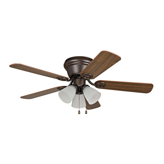
Installation Guide
For Models:
WC42BNK5C3
WC42ORB5C3
WC42WW5C3
E192641
net weight of fan: 11.71 lb. (5.31 kg)
READ THESE INSTRUCTIONS AND
SAVE THEM FOR FUTURE USE
Table of Contents:
Safety Tips. pg. 1
Unpacking Your Fan. pg. 2
Parts Inventory. pg. 2
Installation Preparation. pg. 3
Hanging Bracket Installation. pg. 3
Preparation for Wiring. pg. 4
Wiring. pg. 4
Fan Assembly. pg. 5
Motor Housing Assembly. pg. 5
Blade Assembly. pg. 6
Light Kit Assembly. pgs. 6 - 7
Testing Your Fan. pg. 7
Troubleshooting. pg. 8
Parts Replacement. pg. 8
Warranty. pg. 8
PRINTED IN CHINA
Advertisement
Chapters
Table of Contents

Related Manuals for Litex WC42BNK5C3


Summary of Contents for Litex WC42BNK5C3
-
Page 1: Table Of Contents
READ THESE INSTRUCTIONS AND SAVE THEM FOR FUTURE USE Installation Guide For Models: Table of Contents: WC42BNK5C3 Safety Tips. pg. 1 WC42ORB5C3 Unpacking Your Fan. pg. 2 WC42WW5C3 Parts Inventory. pg. 2 Installation Preparation. pg. 3 Hanging Bracket Installation. pg. 3 Preparation for Wiring. -
Page 2: Safety Tips
SAFETY TIPS. WARNING: To reduce the risk of electrical shock, turn off the electricity to the fan at the main fuse box or circuit panel before you begin the fan installation or before servicing the fan or installing accessories. READ ALL INSTRUCTIONS AND SAFETY INFORMATION CAREFULLY BEFORE INSTALLING YOUR FAN AND SAVE THESE INSTRUCTIONS. -
Page 3: Unpacking Your Fan
1. Unpacking Your Fan. Carefully open the packaging. Remove items from Styrofoam inserts. Remove motor housing and place on carpet or Styrofoam to avoid damage to finish. Do not discard fan carton or Styrofoam inserts should this fan need to be returned for repairs. -
Page 4: Installation Preparation
3. Installation Preparation. blade edge To prevent personal injury and damage, ensure inches that the hanging location allows the blades a 7 feet (76cm) clearance of 7ft. (2.13m) from the floor and 30in. (2.13m) (76cm) from any wall or obstruction. This fan is suitable for room sizes up to 144 10ft. -
Page 5: Preparation For Wiring
notched 5. Preparation for Wiring. Locate notched end on bar at top of motor assembly. Lift motor assembly to hanging bracket and slide notched end of bar on the motor assembly into square opening on hanging hanging bracket (see diagram at right). This will allow the bracket motor assembly to hang out of the way while wiring. -
Page 6: Fan Assembly
7. Fan Assembly. Locate 4 motor mounting screws and washers in hardware pack. Carefully push wiring and wire connectors into outlet box. Leave motor motor notched end of bar on motor assembly mounting mounting in square opening of hanging bracket screws screws and lift the other end of motor... -
Page 7: Blade Assembly
9. Blade Assembly. Time Saver: Washers for blade screws can be set on each blade screw prior to installing blades. motor housing Locate 15 blade attachment screws and washers in one of the hardware packs. Hold blade arm up to blade and align holes. Insert 3 blade attachment screws (along with washers) blade attachment with fingers first and then tighten screws... -
Page 8: Testing Your Fan
10. Light Kit Assembly. (cont.) Connect WHITE wire from switch housing to WHITE wire from light kit fitter. Connect BLUE motor housing (or BLACK) wire from switch housing to BLACK wire from light kit fitter. Be sure molex switch connections snap together completely. housing Align holes in light kit fitter with holes in switch housing. -
Page 9: Troubleshooting
2. Verify that reverse switch is set completely in 1-800-527-1292 to arrange for return of fan. Return either direction. fan, shipping prepaid, to Litex Industries, Ltd. We will 3. Check to be sure fan is wired properly. repair or ship you a replacement fan, and we will pay the return shipping cost. - Page 10 LEER ESTAS INSTRUCCIONES Y GUARDARLAS PARA UTILIZACION FUTURA Guía de instalación Para modelos: Indice de materias: WC42BNK5C3 Sugerencias de seguridad. Pág. 1 WC42ORB5C3 Desempaquetado del ventilador. Pág. 2 WC42WW5C3 Inventario de piezas. Pág. 2 Preparación para la instalación. Pág. 3 Instalación del soporte de montaje.
-
Page 11: Sugerencias De Seguridad. Pág
SUGERENCIAS DE SEGURIDAD. ADVERTENCIA: Para evitar la posibilidad de una descarga eléctrica, desconectar la corriente en la caja de fusibles principal o el interruptor protector antes de iniciar la instalación del ventilador o antes de repararlo o instalar accesorios. LEER TODAS LAS INSTRUCCIONES E INFORMACIÓN DE SEGURIDAD CUIDADOSAMENTE ANTES DE INSTALAR SU VENTILADOR Y GUARDAR ESTAS INSTRUCCIONES. -
Page 12: Desempaquetado Del Ventilador. Pág
1. Desempaquetado del ventilador. Abrir el empaque cuidadosamente. Sacar los artículos del embalaje. Sacar el motor y ponerlo en una alfombra o en el embalaje para evitar rayar el acabado. Guardar la caja de cartón o el empaquetamiento original en caso de que tenga que mandar el ventilador para alguna reparación. -
Page 13: Preparación Para La Instalación. Pág
3. Preparación para la instalación. borde del aspa Para prevenir daño corporal y otros daños, estar 76cm seguro de que el lugar en donde va a colgar el ventilador le permite un espacio libre de 2,13m (7 2,13m pulg.) (7 pies) pies) entre las puntas de las aspas y el piso y 76cm (30 pulg.) entre las aspas y cualquier pared u otra 3,05m - 3,66m... -
Page 14: Preparación Para La Instalación Eléctrica. Pág
extremidad que se usa 5. Preparación para la para colgar instalación eléctrica. Localizar la extremidad de la barra en la parte superior de la unidad del motor que tenga muescas. Subir la unidad del motor al soporte de montaje y meter la extremidad de la barra en la soporte unidad del motor que tenga muescas dentro de la de montaje... -
Page 15: Ensamblaje Del Ventilador. Pág
7. Ensamblaje del ventilador. Localizar los 4 tornillos y arandelas para montaje del motor en un paquete de artículos de ferretería. Cuidadosamente meter el cableado y los tornillos y tornillos y conectores para cable dentro de la caja de arandelas arandelas salida. -
Page 16: Colocación De Las Aspas. Pág
9. Colocación de las aspas. Para ahorrar tiempo: Se pueden poner las arandelas en los tornillos que son para las aspas antes de colocar las aspas. bastidor del motor Localizar 15 tornillos para fijar las aspas y 15 arandelas en uno de los paquetes de artículos de ferretería. Agarrar uno de los brazos para las aspas y juntarlo con una de las aspas para alinear los agujeros. -
Page 17: Verificación Del Funcionamiento Del
10. Instalación del juego de luz. (cont). Conectar el cable BLANCO de la caja de encendido al cable BLANCO del conectador para el juego de luz. Conectar el cable AZUL (o NEGRO) de la caja de encendido al cable NEGRO del conectador para el juego de luz. - Page 18 Litex Industries. Nosotros repararemos el motor al comprador o le enviaremos 3. Verificar que se hizo correctamente la conexión uno de reemplazo y Litex pagará los gastos de envío de cables en la caja de salida. de regreso.
Need help?
Do you have a question about the WC42BNK5C3 and is the answer not in the manual?
Questions and answers