Table of Contents
Advertisement
Quick Links
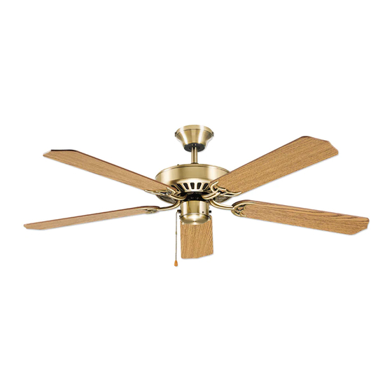
Installation Guide
For Models:
ULT52AB5
ULT52ABZ5
ULT52AN5
ULT52BB5
ULT52CS5
ULT52MBK5
ULT52MG5
ULT52VP5
ULT52WB5
ULT52WW5
E144735
net fan weight: 14 lbs. (6.4 KG)
Table of Contents:
Safety Tips. pg. 1
Unpacking Your Fan. pg. 2
Installation Preparation. pg. 3
Fan Assembly. pgs. 4 - 5
Wiring. pg. 6
Canopy Assembly. pg. 6
Blade Assembly. pg. 7
Testing Your Fan. pg. 7
Troubleshooting. pg 9
PRINTED IN CHINA
Advertisement
Table of Contents

Related Manuals for Litex ULT52AB5


Summary of Contents for Litex ULT52AB5
-
Page 1: Table Of Contents
Installation Guide For Models: ULT52AB5 ULT52ABZ5 ULT52AN5 ULT52BB5 ULT52CS5 ULT52MBK5 ULT52MG5 Table of Contents: ULT52VP5 Safety Tips. pg. 1 ULT52WB5 Unpacking Your Fan. pg. 2 ULT52WW5 Installation Preparation. pg. 3 Fan Assembly. pgs. 4 - 5 Wiring. pg. 6 Canopy Assembly. pg. 6 Blade Assembly. -
Page 2: Safety Tips
SAFETY TIPS. WARNING: To reduce the risk of electrical shock, turn off the electricity to the fan at the main fuse box or circuit panel before you begin the fan installation or before servicing the fan or installing accessories. Read all instructions and safety information carefully before installing your fan and save these instructions. -
Page 3: Unpacking Your Fan
1. Unpacking Your Fan. Carefully open the packaging. Remove items from Styrofoam inserts. Remove motor housing and place on carpet or Styrofoam to avoid damage to finish. Do not discard fan carton or Styrofoam inserts should this fan need to be returned for repairs. -
Page 4: Installation Preparation
3. Installation Preparation. blade edge To prevent personal injury and damage ensure that the hanging location allows the blades a inches inches (76 cm) clearance of 84" (213 cm) from the floor and 30" (213 cm) (76 cm) from any wall or obstruction. This fan is suitable for room sizes up to 400 12 ft. -
Page 5: Fan Assembly. Pgs
5. Fan Assembly. (downrod). set screw hole If you wish to extend the hanging length of your set screw fan you must purchase a matching downrod of stop pin the desired length. To remove the hanging ball from the 4-inch downrod, loosen the set screw on the hanging hanging ball ball. - Page 6 5. Fan Assembly (downrod). (cont.) With the hanging bracket secured to the junction box and able to support the fan you are now ready to hang your fan. Grab the fan firmly with two hanging bracket tab hands. Slide downrod through opening in hanging hanging ball slot bracket and let hanging ball rest on the hanging bracket.
-
Page 7: Wiring
7. Wiring. Important: Be sure outlet box is properly grounded white supply wire or that a ground (GREEN or Bare) wire is present. ground (green or bare) black supply wire Make sure all electrical connections comply with Local Codes or Ordinances and the National from ceiling Electrical Code. -
Page 8: Blade Assembly
9. Blade Assembly. Locate 15 blade attachment screws and washers in hardware pack. Hold blade arm up to blade and align holes. Insert 3 blade motor housing attachment screws and washers with fingers. Tighten securely with a Phillips screwdriver. Repeat procedure for the remaining blades. blade Remove blade arm screws and lock washers from fan motor and set aside. -
Page 9: Light Kit Assembly (Optional)
11. Light Kit Assembly (optional). motor housing WARNING: Failure to disconnect power supply at main panel prior to light kit assembly may result in serious injury. switch housing If you wish to use your fan with a light kit: Remove three screws from switch housing. Remove switch housing plate from switch housing. -
Page 10: Troubleshooting
Service at 1-800-527-1292 to arrange for return of fan. 1. Check wall switch to fan. Return fan, shipping prepaid to Litex Industries, Ltd. We will 2. Verify that reverse switch is set completely in repair or ship you a replacement fan, and we will pay the either direction.
Need help?
Do you have a question about the ULT52AB5 and is the answer not in the manual?
Questions and answers