Sign In
Upload
Manuals
Brands
Bender Manuals
Monitor
COMTRAXX CP700
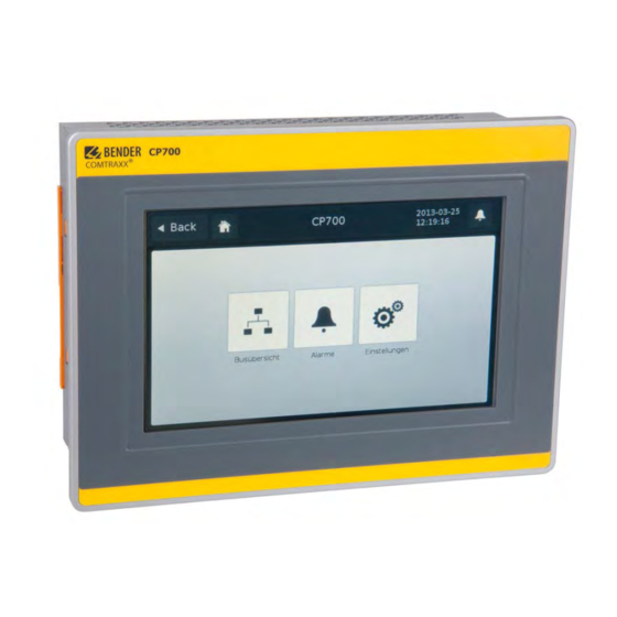
Bender COMTRAXX CP700 Touchscreen Monitor Manuals
Manuals and User Guides for Bender COMTRAXX CP700 Touchscreen Monitor. We have
2
Bender COMTRAXX CP700 Touchscreen Monitor manuals available for free PDF download: Manual, Quick Start Manual
Bender COMTRAXX CP700 Manual (172 pages)
Condition monitor for the connection of Bender BMS devices and universal measuring devices to TCP/IP networks
Brand:
Bender
| Category:
Monitor
| Size: 4.52 MB
Table of Contents
Table of Contents
3
1 Making Effective Use of this Document
9
How to Use this Manual
9
Quick Start
9
2 Safety Instructions
11
Work Activities on Electrical Installations
11
Intended Use
11
Address Setting and Termination
12
Delivery Conditions, Guarantee, Warranty and Liability
12
3 Product Description
13
Scope of Supply
13
Device Features
13
Possible Applications
13
Description of Function
14
Interfaces
14
Process Image
14
CP700-Compatible Devices
14
Functions Available Via Touch Screen
15
Functions Available Via the Web User Interface
15
Software Products Used
16
4 Installation, Connection and Commissioning
17
Preliminary Considerations
17
Installing the Device
17
Essential Information on Mounting
17
Type of Installation
18
Practice
18
Connection of the Device
20
Overview of the Bus Device Interfaces
20
DC 24 V Power Supply
21
Earthing
21
BMS Bus, Modbus/Rtu
22
Commissioning
23
5 Display and Operating Elements
25
Operating Elements at the Rear of the Device
25
Status Leds
26
Battery
26
Compactflash Card
26
Touchscreen
27
Operation Via Touch Screen
28
Main Menu
28
Settings" Menu
29
Interface" Menu
29
Language" Menu
31
Alarms" Menu
32
Bus Overview" Menu
32
Displaying the Device Info for CP700
33
Using the Functions for Bender PEM
33
6 Web User Interface of the CP700
35
Menu Structure of the Web User Interface
35
Browser Configuration
37
Initial Operation of the Web User Interface
37
Start Page and Operating Language
38
Opening the Start Page
38
Changing the Language
38
Menu Bar
39
Bus Overview and Device Information
40
Creating a Password Protection for CP700
40
Buttons for the List of Bus Devices
42
CP700 on the Internal BMS Bus
43
Querying Device Information
43
Displaying the Help Text
44
Loading the Menu of a Bus Device
45
Displaying the Settings of a Bus Device
45
Creation and Further Processing of a Bus Device Back-Up/Report
46
Creating a Backup
46
Show the Backup
47
Creating a New Backup with a Comparison of the Device Parameters
47
Using a Backup for Parameter Setting
48
History Memory
50
Displaying the History Memory
50
Evaluating the History Memory
51
Exporting the History Memory
52
Delete the History Memory
52
Displaying the History Memory of BMS Devices
52
Data Logger
53
Data Logger Setting
53
Displaying the Data Logger
53
Evaluating the Data Logger
54
Apply the Filter to the Graphical Representation
58
Exporting the Data Logger
58
Deleting the Data Logger
59
Displaying the Data Logger of BMS Devices
59
Parameter Setting for Bus Devices
60
Operating Elements for Parameter Setting
60
Setting the Parameters for RCMS460-L
61
Parameter Setting of the CP700 Using the "Settings" Menu
62
Entering Individual Texts
65
Enter Individual Texts for an RCMS460-L
65
Displaying, Filtering, Exporting and Importing Individual Texts
67
Displaying Individual Texts
67
Filtering Entries
67
Exporting Individual Texts
68
Editing and Importing Individual Texts
69
E-Mail Notification in the Event of an Alarm
71
Create Templates: to Whom and When Is an E-Mail to be Sent
71
Select Devices and Channels that Are to Trigger an E-Mail Notification
74
Displaying an E-Mail Overview
75
Using the Device Failure Monitoring Function
76
Activating/Deactivating Device Failure Monitoring Function
77
In the Bus Overview
77
Displaying Overview Device Failure Monitoring and Adding Devices
78
Alarms
80
Tools
81
BMS Recording
82
BMS Analyser
83
BMS Log Files
86
Network Parameters
86
Socket State
87
Software Update
88
Software Options and Licensing
90
Identifying Activated Software Options
90
Acquiring Licences for Additional Software Options and Loading the Licence File
91
Activate Acquired Software Options
92
Modbus Register
93
Modbus Representation of Device Information
93
Modbus Representation of a BMS Channel
94
Modbus Control Commands for BMS Devices
95
10Individual Texts, Device Failure Monitoring, E-Mail Configuration
96
Visualisation
97
Create Visualisation
97
Creating a New View Page
99
Adding a Link to View
101
Adding New Elements
102
Adding a New Text Line
104
Adding a New Data Logger
105
Save, Export, Import and Exit Configuration
106
Save and Exit Configuration
106
Export Configuration
106
Import Configuration
106
Using the Visualisation Function
107
Open the Operating Manual as PDF File
109
System Visualisation
110
Start System Visualisation
110
Check the Activation of the Application Memory
110
Add New Device to System Visualisation
111
Change or Delete the Device
111
Export System Visualisation
112
Import System Visualisation
112
Sort System Visualisation
112
Use System Visualisation
113
Manage Modbus Devices
114
Adding a New Modbus Device
114
Delete Modbus Device
115
Editing a Modbus Device
115
Creating, Editing or Deleting Templates
115
Add New Template
116
Delete Template
116
Change Template
116
Manage Virtual Devices
117
Adding a New Virtual Device
117
Deleting a Virtual Device
118
Changing a Virtual Device
118
Setting the Channels of a Virtual Device
119
7 Data Access Using the Modbus/Tcp Protocol
121
Exception Code
121
Modbus Requests
121
Modbus Responses
122
Structure of an Exception Code
122
Modbus Address Structure for BMS Devices
122
8 Process Image in the Memory of the CP700
123
Data Request
123
Modbus Function Code
123
How Are Memory Areas Organised
123
Memory Scheme of the Process Image
124
BMS Device Address Assignment Within the Modbus
124
Memory Scheme of an Individual BMS Device
124
Device Type
126
Timestamp
126
C = Common Alarm and D = Device Lost (Device Failure)
126
Channels 1 to 32 with Analogue And/Or Digital Values
126
Float = Floating Point Value of the BMS Channels
127
A&T = Alarm Type and Test Type (Internal)
127
R&U = Range and Unit
128
Channel Description
129
Channel 33 to 64
130
Reference Data Records of the Process Image
131
Address Assignment of the Reference Data Record
131
Reference Value on Channel 1
131
Reference Value on Channel 2
132
Explanation of How to Access Floating Point Values
132
Channel Descriptions for the Process Image
133
Modbus Control Commands for BMS Devices
138
9 Monitor for Power Quality
141
Displaying Alarms/Measured Values
141
Triggering Alarm Messages in the Case of Events
142
Making Settings for Events
142
Creating Template for Events
142
Activate Template for Events
143
Acknowledging Alarm Messages for Events
143
Displaying a PEM
144
Displaying the Phasor Diagram of a PEM
145
Displaying Harmonics by Means of PEM
146
Waveform Recorder of a PEM575 Universal Measuring Device
148
Using the Waveform Recorder
148
Setting the Waveform Recorder
152
Setting the Trigger Event for the Waveform Recorder
153
Setting the Trigger Event Undervoltage/Overvoltage (SAG/SWELL)
153
Setting the Trigger Event Transients
154
Displaying the Power Diagram of a PEM
155
Set the Options
156
Data Recorders and High-Speed Data Recorders
157
10 Technical Data
159
Data in Tabular Form
159
Dimension Diagram
161
Control Panel Cut-Out
161
Standards, Approvals, Certifications
162
Ordering Information
162
Disposal
162
11 Troubleshooting
163
Damage in Transit
163
Malfunctions
163
What Should be Checked
163
Fault Messages with Error Code
164
Frequently Asked Questions
164
Where Do You Get Help
164
Battery Change
165
Index
167
Advertisement
Bender COMTRAXX CP700 Quick Start Manual (8 pages)
Condition Monitor for Bender BMS devices and universal measuring devices
Brand:
Bender
| Category:
Monitor
| Size: 0.88 MB
Advertisement
Related Products
Bender LINETRAXX CMS460-D4
Bender LINETRAXX CMS460-D4-2
Bender COMTRAXX CP9 Series
Bender COMTRAXX CP915
Bender COMTRAXX CP907-F
Bender COMTRAXX CP921-F
Bender COMTRAXX CP924-F
Bender COMTRAXX CP915-G
Bender COMTRAXX CP924-G
Bender COMTRAXX CP9 I Series
Bender Categories
Measuring Instruments
Monitor
Control Unit
Control Panel
Relays
More Bender Manuals
Login
Sign In
OR
Sign in with Facebook
Sign in with Google
Upload manual
Upload from disk
Upload from URL