
Related Manuals for Taylor C722


Summary of Contents for Taylor C722
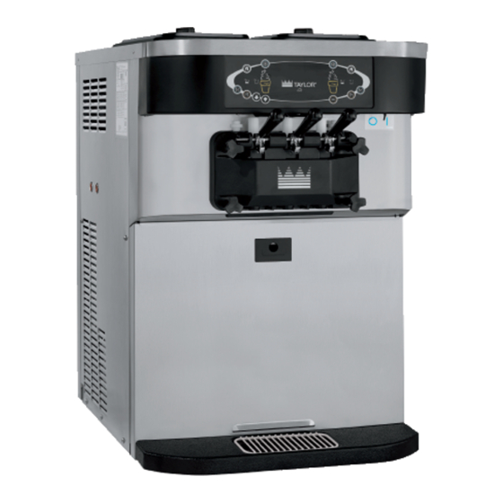
- Page 1 OPERATOR’S MANUAL Model C722 Soft Serve Freezer Original Operating Instructions 080568-M 2/22/12 (Original Publication) (Updated 8/19/2020)
- Page 2 Note: Only instructions originating from the factory or its authorized translation representative(s) are considered to be the original set of instructions. © 2012 Taylor Company 080568-M Any unauthorized reproduction, disclosure, or distribution of copies by any person of any portion of this work may be...
-
Page 3: Table Of Contents
Optional Carts ....................1-3 Refrigerant ......................1-4 Section 2: To the Operator Section 3: Safety Section 4: Operator Parts Identification Model C722......................4-1 Door and Beater Assembly ................4-3 X69928-14S Pump A. - Mix Simplified S.S............4-4 Accessories......................4-5 Brushes ......................4-6 Optional Carts .................... - Page 4 Table of Contents Section 7: Operator Checklist During Cleaning and Sanitizing ................. 7-1 Troubleshooting Bacterial Count ............... 7-1 Regular Maintenance Checks................7-1 Winter Storage....................7-2 Section 8: Troubleshooting Guide Section 9: Parts Replacement Schedule Section 10: Limited Warranty on Equipment Section 11: Limited Warranty on Parts 080568-M...
-
Page 5: Section 1: To The Installer
6 in. (152 mm) on the left and right sides and 0.0 in. on applicable code of the local area for the industry the back. The C722 equipped with top air discharge that standards on lockout/tagout procedures before requires 6 in. (152 mm) on the left side, 0.0 in. on the beginning any installation or repairs. -
Page 6: Water Connections
The main power supplies to the machine must be disconnected prior to performing installation, repairs, or maintenance. • For Cord-Connected Machines: Only Taylor service technicians or licensed electricians may install a plug or replacement cord on the machine. To the Installer... -
Page 7: Beater Rotation
Supply cords used with this machine shall be • It is recommended that beater rotation adjustment be oil-resistant, sheathed flexible cable not lighter performed by an authorized Taylor service technician. than ordinary polychloroprene or other equivalent synthetic elastomer-sheathed cord Optional Carts... -
Page 8: Refrigerant
Filling the cylinder to approximately 80% will allow for systems. For information regarding applicable local laws, normal expansion. please contact your local authorized Taylor distributor. CAUTION! Use only approved refrigerant IMPORTANT! Refrigerants and their listed on the machine's data label or authorized through a associated lubricants may be extremely moisture manufacturer's technical bulletin. -
Page 9: Section 2: To The Operator
Section 2 Your freezer has been carefully engineered and Note: Your Taylor warranty is valid only if the parts are manufactured to give you dependable operation. authorized Taylor parts, purchased from the local authorized Taylor distributor, and only if all required... - Page 10 It should also be noted that Taylor does not warrant the refrigerant used in its equipment. For example, if the refrigerant is lost during the course of ordinary service to...
-
Page 11: Section 3: Safety
Safety Section 3 We at Taylor Company, are concerned about the safety of machine's frame. the operator when he or she comes in contact with the freezer and its parts. Taylor has gone to extreme efforts to design and manufacture built in safety features to WARNING! This machine must NOT be protect both you and the service technician. - Page 12 WARNING! Only install this machine in a Failure to follow these instructions may result in location where its use and maintenance is restricted to electrocution. Contact your local authorized Taylor trained personnel. Failure to comply may result in distributor for service.
- Page 13 Noise Level: Airborne noise emission does not exceed 78 dB(A) when measured at a distance of 39 in. (1.0 m) from the surface of the machine and at a height of 62 in. (1.6 m) from the floor. Safety Model C722...
- Page 14 SAFETY Notes: Safety Model C722...
-
Page 15: Section 4: Operator Parts Identification
Operator Parts Identification Section 4 Model C722 Figure 4-1 Operator Parts Identification Model C722... - Page 16 OPERATOR PARTS IDENTIFICATION Model C722 Exploded View Parts Identification Item Description Part No. Item Description Part No. Kit A.-Hopper CVR 14 QT BLA X69146 Shield-Splash-Wire 046177-SP Orifice 022465-100 Pan A.-Drip 15 1/8 Long X51601 O-ring-11/16 OD X .103W Red 016132...
-
Page 17: Door And Beater Assembly
024278 Screw-Adjustment-5/16-24 056332 Blade-Scraper-Plastic 084978 O-ring-1/4 OD X .070W 015872 Beater A.-2.8QT-1 Pin X80291 Handle A.-Draw X56421-1 Shaft-Beater 081707 Nut-Stud-Black 3.250 Long 058765 Seal-Drive Shaft 032560 Plug-Prime Twin 059936 *Not available separately. Order X50350 kit. Operator Parts Identification Model C722... -
Page 18: X69928-14S Pump A. - Mix Simplified S.s
Pump A.-Mix Simplified S.S. X69928-14S Pin-Retaining X55450 Adaptor-Mix Inlet-SS-Red 069921 Cylinder-Pump Hopper Softserve 069920 Gasket-Simplified Pump Valve 086097 Tube A.-Feed-Left *C722* X69919 Cap-Valve Body SS 056874-14 Tube A.-Feed-Right *C722* X69924 O-ring-2-1/8 OD X .139W-#225 020051 Sleeve A.-Mix Pump *HT* X44761 Piston-Pump-Simpl.-Short... -
Page 19: Accessories
OPERATOR PARTS IDENTIFICATION Accessories Apply the appropriate Taylor approved food safe lubricant. Figure 4-4 Item Description Part No. Item Description Part No. Lubricant-Taylor 047518 Tool-Mix Pump Shaft Removal 057167 Tool-O-ring Removal 048260-WHT Pail-10 QT 013163 Sanitizer-Stera Sheen See Note Kit A.-Tune X49463-97 *A sample container of sanitizer is sent with the machine. -
Page 20: Brushes
Description Part No. Item Description Part No. Brush-Rear BRG. - 1" X 2" 013071 Brush-Mix Pump Body- 3 X 7 023316 Brush-Double End 013072 Brush-Set LVB 050103 Brush-Draw Valve 1 X 2 X 17 013073 Operator Parts Identification Model C722... -
Page 21: Optional Carts
Caster-3” SWV 3/4-10 Stem 030307 Note: This is an ADA-compliant height cart, not w/Brake equipped with a door. Panel-Side-STD Cart 069428 Panel-Rear-STD Cart 069429 Note: This is a standard-height cart with reversible front door panel and rear panel. Operator Parts Identification Model C722... - Page 22 OPERATOR PARTS IDENTIFICATION Notes: Operator Parts Identification Model C722...
-
Page 23: Section 5: User Interface
User Interface Section 5 Model C722 Figure 5-1 Item Description Power Switch Liquid Crystal Display Keypads Mix Out Indicators Standby Indicators Mix Low Indicators Select Key Service Menu Key Brush Clean Counter Arrow Keys Topping Heater Keys (not functional) User Interface... -
Page 24: Symbol Definitions
To better communicate in the international arena, symbols have replaced words on many of our operator = Standby switches, function, and fault indicators. Your Taylor machine is designed with these international symbols. The following chart identifies the symbol definitions. = Topping Heater-Left... - Page 25 To cancel any function, press the key again. The light and 101187 the mode of operation will shut off. Topping Heater Symbols The Topping Heater symbols are not functional on the Model C722. Figure 5-2 User Interface Model C722...
-
Page 26: Optional Feed Tube (Back-Up Option)
To place the unit into the Standby mode, press the STANDBY key. Remove the air orifice. Lubricate the o-rings located on the end of the feed tube without the hole. Place that end of the tube into the mix inlet hole. User Interface Model C722... -
Page 27: Manager's Menu
SEL symbol, and the Cone symbol (Menu display will exit the Menu program when the SEL symbol Display) will be lit when the ACCESS CODE screen is is selected.(See Figure 5-5.) displayed. (See Figure 5-4.) 13413 13907 Figure 5-5 Figure 5-4 User Interface Model C722... - Page 28 Arrow symbol to move the Arrow cursor(>) to Yes and press the SEL symbol. The SERVINGS COUNTER will DAYLIGHT SAVING TIME reset to zero and exit back to the Manager's Menu. ENABLED > Enable Disable Reset Counters ARE YOU SURE? > User Interface Model C722...
- Page 29 DST END MONTH > AUTO START TIME 00:00 Use the arrow symbols to program the AUTO START TIME by increasing or decreasing the hour setting above the cursor. Press the SEL symbol to advance the cursor User Interface Model C722...
- Page 30 OFF position. Wait 5 minutes for the machine to cool. Place the power switch in the ON position and restart in AUTO. L/R HPR Therm Fail—The hopper thermistor failed. Call for service. L/R BRL Therm Fail—The freezing cylinder thermistor failed. Call for service. User Interface Model C722...
- Page 31 Pressing the SEL symbol with the arrow cursor next to No will return to the Manager's Menu. Pressing the SEL SOFTWARE VERSION symbol with the arrow cursor next to Yes will connect to C722 CONTROL UVC4 the network if a gateway card is connected. VERSION V00.00.000 > Next...
- Page 32 USER INTERFACE Notes: 5-10 User Interface Model C722...
-
Page 33: Section 6: Operating Procedures
Operating Procedures Section 6 The Model C722 is a medium-capacity soft serve 11470 machine. Mix is stored in the hoppers. The machine is equipped with a three-spout door and two 2.8 qt. (2.7 L) capacity freezing cylinders. We begin our instructions at the point where we enter the... - Page 34 Figure 6-4 9. If the beater shoes are in good condition, install the If the blades are in good condition, place the rear beater shoes. scraper blade over the rear holding pin on the beater. Operating Procedures Model C722...
- Page 35 11533 Slide the two O-rings into the grooves on each prime plug. Apply an even coat of Taylor Lube to the O-rings and shafts. Figure 6-8 11468 11.
- Page 36 15. Insert the prime plugs into the holes in the top of the 10526 freezer door, and push down. 101293 Apply the appropriate Taylor approved food safe lubricant. Figure 6-13 18. Lubricate the inside of the freezer door spouts, top Figure 6-11 and bottom.
- Page 37 The draw handle should be adjusted to provide a flow rate of 5 oz. to 7-1/2 oz. (148 ml to 222 ml)) of product by weight per 10 seconds. Figure 6-20 Operating Procedures Model C722...
-
Page 38: Mix Pump Assembly
101428 15206 Apply the appropriate Taylor approved food safe lubricant. Figure 6-21 Figure 6-23 4. Insert the piston into the retaining pin hole end of the Mix Pump Assembly pump cylinder. - Page 39 11. Install one red O-ring on each end of the mix feed tube, and thoroughly lubricate it. 15193 Apply the appropriate Taylor approved food safe lubricant. Figure 6-28 The adapter must be positioned into the notch located at the end of the pump cylinder.
-
Page 40: Sanitizing
Thoroughly lubricate the O-rings and shaft. Do not 12029 lubricate the hex end of the shaft. 15009 Apply the appropriate Taylor approved food safe lubricant. Figure 6-34 Note: You have just sanitized the mix hopper and Figure 6-32 parts. Therefore, make sure your hands are clean ... -
Page 41: Priming
When only fresh mix is flowing, close the spout. Draw off the remaining sanitizing solution. draw valve. 13. Once the sanitizer stops flowing from the door spout, press the Wash and Mix Pump symbols and close the draw valve. Operating Procedures Model C722... -
Page 42: Closing Procedure
Note: These procedures must be completed every day. push the prime plug down. 101429 ALWAYS FOLLOW LOCAL HEALTH CODES. To disassemble the Model C722, the following items will be needed. • Two cleaning and sanitizing pails • Sanitizer/cleaner •... -
Page 43: Hopper Cleaning
Using the double-ended brush, clean the mix inlet hole. Note: Do not brush-clean the mix inlet hole while the machine is in the Wash mode. 6-11 Operating Procedures Model C722... -
Page 44: Manual Brush-Cleaning
(See Figure 6-43.) Figure 6-42 10531 Note: If the drip pans are filled with an excessive amount of mix, the driveshaft seal(s) or O-ring(s) should be replaced or properly lubricated. Figure 6-43 6-12 Operating Procedures Model C722... - Page 45 (See Figure 6-44.) 12008 Figure 6-44 5. Wipe all exterior surfaces of the freezer with a clean, sanitized towel. Note: The brush-clean counter will reset to zero at this time. 6-13 Operating Procedures Model C722...
- Page 46 OPERATING PROCEDURES Notes: 6-14 Operating Procedures Model C722...
-
Page 47: Section 7: Operator Checklist
Deteriorated or cracked water lines adequate job of cleaning or sanitizing. should be replaced only by an authorized Taylor The temperature of the mix in the mix hopper and distributor. -
Page 48: Winter Storage
This is extremely important. Failure to follow this procedure may cause severe and costly damage to the refrigeration system. Your local Taylor distributor can perform this winter storage service for you. Operator Checklist Models C722... -
Page 49: Section 8: Troubleshooting Guide
3. The product is too soft. a. Draw rate is set too fast. a. Adjust draw rate: 5 oz. to 7-1/2 oz. (142 g to 213 g) of product by weight in 10 seconds. Troubleshooting Guide Model C722... - Page 50 Call a service technician. - - - work forward. e. Worn rear shell bearing. e. Call a service technician. - - - f. Gearbox out of alignment. f. Call a service technician. - - - Troubleshooting Guide Model C722...
- Page 51 (142 g to 213 g) of product by weight drawn. in 10 seconds. b. Pump assembled incorrectly. b. Assemble and lubricate according to instructions in this manual. c. Freezing cylinder not primed c. Drain the freezing cylinder and correctly. reprime the machine. Troubleshooting Guide Model C722...
- Page 52 TROUBLESHOOTING GUIDE Notes: Troubleshooting Guide Model C722...
- Page 53 Inspect and replace if Minimum necessary. Bristle Brush, 1” x 2” Inspect and replace if Minimum necessary. Black Bristle Brush, 1” x 2” Inspect and replace if Minimum necessary. Double-Ended Brush Inspect and replace if Minimum necessary. Parts Replacement Schedule Models C722...
- Page 54 PARTS REPLACEMENT SCHEDULE Notes: Parts Replacement Schedule Models C722...
-
Page 55: Section 10: Limited Warranty On Equipment
LIMITED WARRANTY Taylor warrants the Product against failure due to defect in materials or workmanship under normal use and service as follows. All warranty periods begin on the date of original Product installation. If a part fails due to defect during the applicable warranty period, Taylor, through an authorized Taylor distributor or service agency, will provide a new or remanufactured part, at Taylor’s option, to replace the failed defective part at no charge for the part. - Page 56 7. Failure, damage, or repairs due to faulty installation, misapplication, abuse, no or improper servicing, unauthorized alteration, or improper operation or use as indicated in the Taylor Operator's Manual, including but not limited to the failure to use proper assembly and cleaning techniques, tools, or approved cleaning supplies.
- Page 57 LEGAL REMEDIES The owner must notify Taylor in writing by certified or registered letter to the following address,of any defect or complaint with the Product, stating the defect or complaint and a specific request for repair, replacement, or other correction of the Product under warranty, mailed at least thirty (30) days before pursuing any legal rights or remedies.
- Page 58 LIMITED WARRANTY ON EQUIPMENT Notes: 10-4 Limited Warranty on Equipment Model C722...
-
Page 59: Section 11: Limited Warranty On Parts
Taylor warrants the Parts against failure due to defect in materials or workmanship under normal use and service as follows. All warranty periods begin on the date of original installation of the Part in the Taylor unit. If a Part fails due to defect during the applicable warranty period, Taylor, through an authorized Taylor distributor or service agency, will provide a new or remanufactured Part, at Taylor’s option, to replace the failed defective Part at no charge for the Part. - Page 60 Taylor. 5. Replacement of wear items designated as Class “000” Parts in the Taylor Operator's Manual, as well as any release sheets and clips for the Product's upper platen assembly.
- Page 61 LEGAL REMEDIES The owner must notify Taylor in writing, by certified or registered letter to the following address, of any defect or complaint with the Part, stating the defect or complaint and a specific request for repair, replacement, or other correction of the Part under warranty, mailed at least thirty (30) days before pursuing any legal rights or remedies.
- Page 62 LIMITED WARRANTY ON PARTS Notes: 11-4 Limited Warranty on Parts Model C722...
Need help?
Do you have a question about the C722 and is the answer not in the manual?
Questions and answers