Honeywell Touchpoint Plus Wireless User Manual
Hide thumbs
Also See for Touchpoint Plus Wireless:
- Technical handbook (158 pages) ,
- User manual (71 pages) ,
- Safety manual (8 pages)
Table of Contents
Advertisement
Quick Links
Advertisement
Table of Contents

Related Manuals for Honeywell Touchpoint Plus Wireless


Summary of Contents for Honeywell Touchpoint Plus Wireless
- Page 1 User Guide Touchpoint Plus Wireless...
- Page 2 Revision History Issue Comment ECO no. Date Initial Release HAA190023 April 2019...
- Page 3 Disclaimer In no event shall Honeywell be liable for any damages or injury of any nature or kind, no matter how caused, that arise from the use of the equipment referred to in this manual. Strict compliance with the safety procedures set out and referred to in this manual, and extreme care in the use of the equipment, are essential to avoid or minimise the chance of personal injury or damage to the equipment.
-
Page 4: Table Of Contents
3.1.7 Storage Conditions (With batteries) ................16 3.1.8 IP Rating ......................... 16 3.1.9 Construction ........................17 3.1.10 Touchpoint Plus Wireless Packaging ................17 3.1.11 Packaging Components for Return to Manufacturer ............. 17 3.1.12 Disposal (WEEE Directive).................... 17 3.2 System Construction ......................18 Chapter 4 User Guide ...................... - Page 5 Issue 1 04/19 Touchpoint Plus Wireless 3020M5044_1 User Guide Contents 4.8.4 Navigation – Menu ......................29 4.9 Responding to Alarms ......................30 4.9.1 View Active Alarms ......................30 4.9.2 Accept or Acknowledge an Active Alarm ..............30 4.9.3 Reset a Latched Alarm ....................31 4.10 Event Information ........................
-
Page 6: Chapter 1 Important Safety Information
1.1 Regulatory Approval Markings Products bearing the CE mark conform to all applicable European Directives as stated on the Honeywell product specific EC Declaration of Conformity. Products bearing the UL mark conform to the requirements for Ordinary Locations. The letters C and US mean that the product is certified for use in Canada and the United States of America. -
Page 7: Tpplw General Warnings
Installation must be in accordance with the recognized standards of the appropriate authority in the country concerned. Refer to local, national and company regulations. Do not operate the Touchpoint Plus Wireless system or its components outside of their rated operating specification. -
Page 8: Tpplw General Cautions
Do not use sharp objects to operate the touchscreen as this could irreparably damage the User Interface and adversely affect its IP rating. Use only soft, damp cloths or screen wipes to clean the Touchpoint Plus Wireless. Do not use solvents or abrasives as they will damage the User Interface. -
Page 9: Associated Manuals
The TPPLW Technical Handbook (Pt. No. 3020M5001) contains detailed information on Installation, Commissioning, Maintenance, Repairs, Replacements and Upgrades. It is aimed at Honeywell personnel, qualified technical personnel who are trained on TPPLW, Honeywell partners and OEMs, and it is available in English only. -
Page 10: Chapter 2 Safety Hazards, Warnings And Cautions
Environmental hazards (toxic atmospheres) WARNING Fire and Ignition hazards (Touchpoint Plus Wireless is not ATEX/IECEx Zone 1 certified, and cannot be used in flammable atmospheres, or where oxygen concentrations >25% v/v O 2.1.1 Warnings and Cautions Safety of this equipment is reinforced by the use of safety labels that are fixed to the equipment in a visible manner. -
Page 11: Safety Hazards
The following specific hazards are associated with the installation and use of this equipment: DANGER – IGNITION HAZARD Touchpoint Plus Wireless is not ATEX/IECEx certified, and it may only be installed in safe areas where there are no flammable atmospheres, and no oxygen concentrations >25% v/v O WARNING –... - Page 12 Issue 1 04/19 Touchpoint Plus Wireless 3020M5044_1 User Guide Safety Hazards, Warnings And Cautions 2.1.2 Safety Hazards (Cont.) The following general hazards are associated with the use of this equipment: WARNING – FIRE OR EXPLOSION HAZARD Battery may explode if mistreated. Do not disassemble or dispose of in fire.
-
Page 13: Location And Description Of Warning Labels
Issue 1 04/19 Touchpoint Plus Wireless 3020M5044_1 User Guide Safety Hazards, Warnings And Cautions 2.2 Location and Description of Warning Labels 2.2.1 Safety Warning Labels In accordance with the requirements of the European Standard EN 60825–1, appropriate warning labels are mounted in specified locations on the equipment. -
Page 14: Electrical Hazards
Read the relevant manual before beginning any operating or service procedures. Only personnel trained and certified by Honeywell are authorised to service, fit or remove internal parts. Only the minimum number of trained personnel, consistent with safety, should have access to the area while work is being carried out. -
Page 15: Antistatic Precautions
Safety Hazards, Warnings And Cautions 2.3.3 Antistatic Precautions As with all modern electronic circuits, the Printed Circuit Boards (PCBs) in Touchpoint Plus Wireless systems utilise some static-sensitive components that can be severely damaged if subjected to static discharge. Static can be generated on the human body by friction or movement and is discharged through the first contacted route to earth. -
Page 16: Product Compliance
Check the product rating plate and look for the following marks to ensure that the supplied equipment is suitable for its intended location and purpose: Products bearing the CE mark conform to all applicable European Directives as stated on the Honeywell product specific EC Declaration of Conformity. -
Page 17: Conditions Of Use
Using approved maintenance and servicing procedures. 2.5.1 Training of Personnel Honeywell and / or its distributors can provide training for operators and maintenance personnel. Personnel who have been trained in operation and maintenance shall be limited to carrying out only those procedures and tasks taught during the training course. -
Page 18: Chapter 3 System General Description
Touchpoint Plus Wireless is rated IP65, which means that it is dustproof and can be subjected to low-pressure water without significant ingress. This makes it particularly suited to offices, control rooms and unheated boiler... - Page 19 Issue 1 04/19 Touchpoint Plus Wireless 3020M5044_1 User Guide System General Description Figure 7. Typical Installation Options Figure 8. Controller Exploded View...
-
Page 20: Equipment Specification
3.1 Equipment Specification 3.1.1 Power Requirements The Touchpoint Plus Wireless system is designed to operate on a single phase, 50 to 60 Hz, 110/220 V~(AC) supply with a typical power consumption of less than 105 W. Alternatively it can be connected to a 18–32V... -
Page 21: Weights
Issue 1 04/19 Touchpoint Plus Wireless 3020M5044_1 User Guide System General Description AC 110/220 V manually switchable Voltage Range AC 300 VAC surge for 5 sec without damage Input 50 – 60 Hz ± 6% AC Frequency Range DC Voltage... -
Page 22: Construction
Both cabinets contain a common Earth (ground) rail that must be bonded to Protective Earth (Ground) through an isolation switch that does not disconnect the Earth line. 3.1.10 Touchpoint Plus Wireless Packaging Touchpoint Plus Wireless outer packaging is made from cardboard. Facilities for recycling are widely available. ®... -
Page 23: System Construction
Issue 1 04/19 Touchpoint Plus Wireless 3020M5044_1 User Guide System General Description 3.2 System Construction This figure shows the basic building blocks of the Touchpoint Plus Wireless system. Figure 9. System Layout Before Installation... -
Page 24: Chapter 4 User Guide
Issue 1 04/19 Touchpoint Plus Wireless 3020M5044_1 User Guide Chapter 4 User Guide WARNING Opening the enclosure may expose live electrical circuits. Touching exposed terminals or wires may cause death or serious injury. Always turn off and isolate the system before opening the door. Do not switch back on until the door is reclosed and secured. -
Page 25: User Interface General
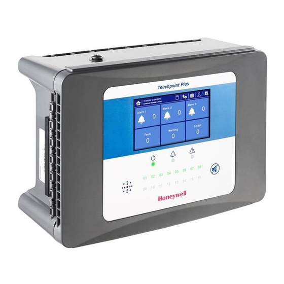
The TPPLW Touchscreen is the primary control and viewing method but there is also an optional Web Interface that currently allows remote viewing only (refer to Ch.4.18 Monitoring TPPLW via the Optional Web Interface for more details). Figure 11. Touchpoint Plus Wireless Controller User Interface The User Interface panel (shown above) has: ... -
Page 26: Switching On And Off
The system start up sequence may last for up to 5 minutes depending on the number of channels in use. When start up is completed, Touchpoint Plus Wireless will display the Input screen, indicating the current status of the system. The Channel tile view is shown below:... -
Page 27: Menu Items And Access Levels
Issue 1 04/19 Touchpoint Plus Wireless 3020M5044_1 User Guide User Guide 4.5 Menu Items and Access Levels The table below details the menu items and access levels for the User Interface. The password hierarchy is Administrator, then Service, then Operator. Broadly speaking, the Administrator can do everything, the Service Engineer can edit channel configuration and do maintenance and calibration, and the Operator can view, acknowledge and reset events. - Page 28 Issue 1 04/19 Touchpoint Plus Wireless 3020M5044_1 User Guide User Guide Menu Item Admin. Service Operator Others mV Input Channel Relay Channel Module Control Panel ...
-
Page 29: Navigation - Active Access Level Icons
4.6 SD Card Usage The SD card is used to store the system event history. Touchpoint Plus Wireless logs all events and all changes to input readings. A notification will be given when the SD card has less than 50 Mb of space remaining. -
Page 30: Inserting Or Replacing Sd Cards
Issue 1 04/19 Touchpoint Plus Wireless 3020M5044_1 User Guide User Guide 4.6.2 Inserting or Replacing SD Cards SD Cards must be unlocked to allow read/write. They must be formatted by TPPLW only, and they should be used for TPPLW data only. Stored data can be transferred or copied to a PC via a Card Reader and the card reused, but care must be taken not to overwrite previously transferred data files held on the PC. -
Page 31: Normal Operation (Safety Functions)
X or [Cancel] button, or by touching the [Home / View] button. 4.8.2 User Interface Screen The User Interface shows the current status of the Touchpoint Plus Wireless system as follows: Channel Summary – Display shows total counts for alarm 1, alarm 2, alarm 3, fault, warning and inhibits ... - Page 32 Issue 1 04/19 Touchpoint Plus Wireless 3020M5044_1 User Guide User Guide The icons in the navigation toolbar are used to navigate through the User Interface options. Channel Input screen: Tile View Summary View Channel detail screen: Wireless Node Icons Wireless Node Online...
-
Page 33: Navigation - Active Events And Filtering
Issue 1 04/19 Touchpoint Plus Wireless 3020M5044_1 User Guide User Guide 4.8.3 Navigation – Active Events and Filtering You can change the list type by touching a filter from one of the Tile views: Key to Filters: Red: Alarm ... -
Page 34: Navigation - Menu
Issue 1 04/19 Touchpoint Plus Wireless 3020M5044_1 User Guide User Guide 4.8.4 Navigation – Menu User must have the appropriate access level password to enter Maintenance, Configuration and System Test options. Note: Depending on menu timeout settings, the system will log out and return to Inputs/Outputs screen. -
Page 35: Responding To Alarms
Issue 1 04/19 Touchpoint Plus Wireless 3020M5044_1 User Guide User Guide 4.9 Responding to Alarms 4.9.1 View Active Alarms Active alarms can be viewed: 1) From the Input screen, select the red filter icon. The screen will display a list of the input channels with active Alarms, starting with the most recent event. -
Page 36: Reset A Latched Alarm
Issue 1 04/19 Touchpoint Plus Wireless 3020M5044_1 User Guide User Guide 4.9.3 Reset a Latched Alarm A latched alarm is one that cannot automatically reset itself when the triggering event has cleared. Note: Operator or higher access level is required... -
Page 37: Resetting Latched Events
Issue 1 04/19 Touchpoint Plus Wireless 3020M5044_1 User Guide User Guide 4.10.3 Resetting Latched Events Note: Password access is required. Acknowledged latched events can be reset in three ways: 5) By logging in and pressing the button for >3 seconds. This will reset ALL latched alarms, faults and warnings, provided that the event has cleared. -
Page 38: To Change Inhibit Timeouts
Issue 1 04/19 Touchpoint Plus Wireless 3020M5044_1 User Guide User Guide 4.11.3 To Change Inhibit Timeouts 16) Log in as Administrator or Service 17) Touch a channel, then touch the Settings icon: 18) Touch [Next] repeatedly until you reach page 7/7, as shown below: 19) Touch the chosen value, enter a new value, and touch [Finish]>[Finish]>[Apply]... -
Page 39: Viewing Input Channels And Input Details
Issue 1 04/19 Touchpoint Plus Wireless 3020M5044_1 User Guide User Guide 4.12 Viewing Input Channels and Input Details icon between Channel Tile>Channel Summary>Channel From the Input screen, toggle the Output. 20) From the Input screen, select Channel List or Channel Tile. -
Page 40: Viewing The Trend Graph
Issue 1 04/19 Touchpoint Plus Wireless 3020M5044_1 User Guide User Guide 4.14 Viewing the Trend Graph The Trend graph is drawn using one minute average readings so it is not suited to viewing short-term signal fluctuations. To view the graph: 24) Touch the Menu Icon>Information>Trend/Plot. -
Page 41: Viewing And Exporting Event History
Issue 1 04/19 Touchpoint Plus Wireless 3020M5044_1 User Guide User Guide 4.15 Viewing and Exporting Event History The event history for the complete system can be viewed in date order (latest first). The history can be filtered by Alarm, Fault, Inhibit, or Warning. -
Page 42: Chapter 5 Daily / Shift Checks
Issue 1 04/19 Touchpoint Plus Wireless 3020M5044_1 User Guide Chapter 5 Daily / Shift Checks In most countries it is a legal requirement to keep itemised, time-stamped operations logs that must be made available to the authorities in the event of a serious accident or incident, and the TPPL digitised event record alone may not satisfy those requirements. -
Page 43: Chapter 6 Maintenance And Scheduled Testing
Ensure that relay activated output systems (i.e. emergency deluge / sirens etc.) are isolated before starting the Relay and mA Output tests. Each sensor connected to Touchpoint Plus Wireless shall be regularly gas calibrated at the interval specified in sensor's user manual. -
Page 44: Routine Testing
Issue 1 04/19 Touchpoint Plus Wireless 3020M5044_1 User Guide Maintenance and Scheduled Testing 6.2 Routine Testing CAUTION When any of the test modes is active, the System Failure relay will activate to indicate that the safety function of the system is not operating. -
Page 45: Mesh Network Test
2) Select the Menu > System test > Mesh Network 6.3 Periodic Scheduled Testing Periodic Scheduled Testing should only be carried out by a Honeywell authorised technician or a qualified person trained in accordance with the TPPLW Technical Handbook. Apart from the safety considerations, Honeywell’s field service technicians will be able to minimise downtime should a fault become apparent during... -
Page 46: Chapter 7 Repairs, Replacements And Upgrades
With the exception of battery replacement, Repairs, Replacements and Upgrades should only be carried out by authorised Honeywell technicians or by qualified persons trained in accordance with the TPPLW Technical Handbook. Failure to follow this advice will invalidate your warranty and may lead to death, injury, or irreparable damage. -
Page 47: How To Replace The Battery Pack
The battery pack has circuitry that puts it into sleep mode to save power when it is not connected and running. Connecting it to a powered-up Touchpoint Plus Wireless causes the battery to change to active mode and it will function normally after a short booster charge. -
Page 48: Chapter 8 Troubleshooting
The error messages are explained in Chapter 12 Event Codes. Contact Honeywell Analytics Technical Support if an error appears repeatedly, if it cannot be cleared, or if it is not listed in Chapter 12 Event Codes. -
Page 49: Chapter 9 Technical Specifications
Issue 1 04/19 Touchpoint Plus Wireless 3020M5044_1 User Guide Chapter 9 Technical Specifications 9.1 Environmental Sealed enclosures are rated IP65, NEMA 4x, and can be installed indoors only in a Pollution Degree 2, 10 to 95 %RH Non-Condensing environment that affords total protection from rain, snow and direct sunlight. -
Page 50: Power Supplies
Issue 1 04/19 Touchpoint Plus Wireless 3020M5044_1 User Guide Technical Specifications 9.3 Power Supplies 9.3.1 External Supplies SMPS Power Supply 156 W AC 110/220 V ±10 % of nominal (manual switching) AC Input Voltage Range (~) DC Input Voltage Range ( — ) DC 18 –... -
Page 51: Chapter 10 Certifications
La performance en conformité avec la CSA est valide uniquement lorsque l’appareil est connecté aux détecteurs de gaz catalytiques Honeywell modèle 705 ou à des détecteurs de gaz 4 - 20 mA dûment approuvés. 10.2 National and International Certificates of Compliance... -
Page 52: Chapter 11 Glossary Of Icons
Issue 1 04/19 Touchpoint Plus Wireless 3020M5044_1 User Guide Chapter 11 Glossary of Icons Icon Description Icon Description Tile View Login Administrator Summary View Menu, System OK History Information AC Power History Alarm Battery Power History Fault SD Card inserted... - Page 53 Issue 1 04/19 Touchpoint Plus Wireless 3020M5044_1 User Guide Glossary of Icons Icon Description Icon Description Icon empty Pop Up for Alarm Cancel Pop Up for Error Processing OK Pop Up for Fault Processing FAIL Pop Up for Inhibit Processing OK...
- Page 54 Issue 1 04/19 Touchpoint Plus Wireless 3020M5044_1 User Guide Glossary of Icons Icon Description Icon Description Factory Calibration Wireless Node Online Factory Calibration Wireless Node Offline Critically Low Battery Wireless Node Router Mode Critically Low Battery Wireless Node Battery Level...
- Page 55 Issue 1 04/19 Touchpoint Plus Wireless 3020M5044_1 User Guide Glossary of Icons Icon Description Icon Description Left screwing view Right screwing view Left-Previous screen Right-Next screen Pause view screwing Wind direction 0 ° Wind direction 45° Wind direction 90 °...
-
Page 56: Chapter 12 Event Codes
Issue 1 04/19 Touchpoint Plus Wireless 3020M5044_1 User Guide Chapter 12 Event Codes Type Code Long Description Triggered Display in Event History Details Main Alarm1 occurred Alarm types: Threshold, Alarm Alarm1 occurred Board CH: xx, Type: xx, xxx[unit] STEL, TWA... - Page 57 Issue 1 04/19 Touchpoint Plus Wireless 3020M5044_1 User Guide Event Codes Type Code Long Description Triggered Display in Event History Details TWA, 5: LowLow, 6:HighHigh, 7: Unknown ) [B/D type] 0:Main, 1:UI, 2:mA Input, 3 : mV input, 4:Relay, 5:mA...
- Page 58 Issue 1 04/19 Touchpoint Plus Wireless 3020M5044_1 User Guide Event Codes Type Code Long Description Triggered Display in Event History Details Remote fault [B/D type] informed by detector Detector In Fault 0:Main, 1:UI, 2:mA Input, 3 : Fault IO board...
- Page 59 Issue 1 04/19 Touchpoint Plus Wireless 3020M5044_1 User Guide Event Codes Type Code Long Description Triggered Display in Event History Details Battery is not being Main Battery not charged [Enclosure] Warning charged Board [Enclosure] 0: master enclosure Main Battery is too low...
- Page 60 Issue 1 04/19 Touchpoint Plus Wireless 3020M5044_1 User Guide Event Codes Type Code Long Description Triggered Display in Event History Details [B/D type] Added IO board 0:Main, 1:UI, 2:mA Input, 3: Info Added IO board UI Board [B/D Type], Slot: xx-x...
- Page 61 Issue 1 04/19 Touchpoint Plus Wireless 3020M5044_1 User Guide Event Codes Type Code Long Description Triggered Display in Event History Details Exported system Exported system Info UI Board configuration Configuration Imported system Imported system Info UI Board configuration Configuration Changed system...
- Page 62 Issue 1 04/19 Touchpoint Plus Wireless 3020M5044_1 User Guide Event Codes Type Code Long Description Triggered Display in Event History Details Info Reserved Info Reserved Forced relay Info Relay output forced UI Board CH: xx Released Relay Info Relay output released...
- Page 63 Issue 1 04/19 Touchpoint Plus Wireless 3020M5044_1 User Guide Event Codes Type Code Long Description Triggered Display in Event History Details Offline wireless Node Main Info Offline Wireless Node UID : xxx, [instrument Wireless Node's Offline State board Name] Removed wireless Node...
-
Page 64: Chapter 13 List Of Figures
Figure 9. System Layout Before Installation Figure 10. Undoing the Security Screws and Opening the Enclosure Figure 11. Touchpoint Plus Wireless Controller User Interface Figure 12. Battery On/Off Switch and Battery Connector Chapter 14 List of Tables Table 1. System Power Calculations Table 2. - Page 65 Toll free: +1 800 538 0363 Fax: +1 847 955 8210 detectgas@honeywell.com www.honeywell.com Asia Pacific Honeywell Analytics Asia Pacific #701 Kolon Science Valley (1) 43 Digital–Ro 34–Gil, Guro–Gu Please Note: While every effort has been made to ensure accuracy in this Seoul 152–729...