Table of Contents
Advertisement
Quick Links
Advertisement
Table of Contents

Subscribe to Our Youtube Channel
Related Manuals for Eaton OnGuard


Summary of Contents for Eaton OnGuard
- Page 1 OnGuard ™ Command Console OnGuard Command Console Installation Manual...
-
Page 2: Table Of Contents
CONTENTS OF THIS DOCUMENT SHALL NOT BECOME PART OF OR MODIFY ANY CONTRACT BETWEEN THE PARTIES� In no event will Eaton be responsible to the purchaser or user in contract, in tort (including negligence), strict liability or other- wise for any special, indirect, incidental or consequential damage or loss whatsoever, including but not limited to damage or... -
Page 3: Before You Begin
OnGuard Command Console SECTION I Installation Manual Before You Begin Before installing the OnGuard Command Console, it is recommended that you do the following: • Read and understand the instruction herein before attempting to • The use of personal protective equipment such as safety glasses,... -
Page 4: Console Capacities
(14° C)�are not limited to) monitor poles, 14� Installation and assembly must be performed by qualified electronic equipment, power distribution personnel� units, cabling, Personal Environment System, and personal items� ONGUARD COMMAND CONSOLE INSTALLATION MANUAL www.eaton.com/onguard... -
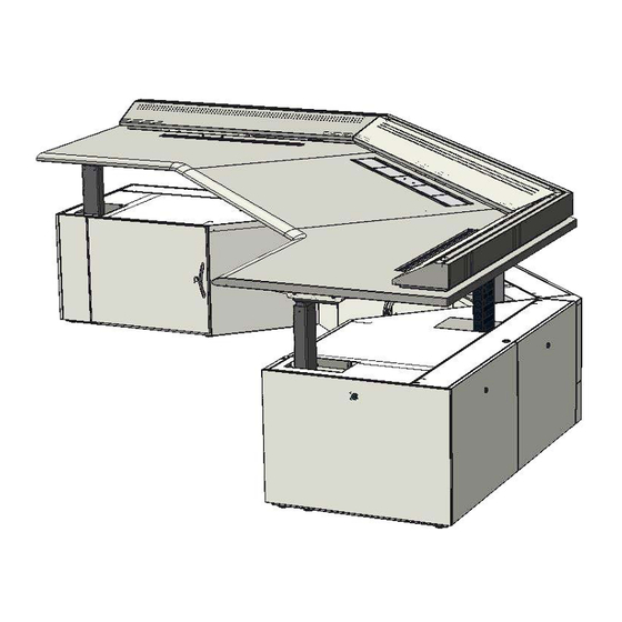
Page 5: Preparing To Assemble The Console
Lockable Rear Panel Lockable End Panel Right Base Cabinet Lift Control Pad Front Work Surface Stiffener RH Worksurface Cable Support Frame Chain LH Worksurface Support Frame Lift Control Box Leveling Feet Bottom Cable Access ONGUARD COMMAND CONSOLE INSTALLATION MANUAL www.eaton.com/onguard... -
Page 6: Assembly Hardware
" Lock Nut (Silver) (6 pcs�) ⁄ " Lock Nut (Silver) (5 pcs�) ⁄ " Star Washer (Silver) 5 pcs�) Wire Stay (6 pcs�) Monitor Pole Sliding Bracket (2 pcs�) Center Monitor Pole Bracket (2 pcs�) Clip (1 pc�) ONGUARD COMMAND CONSOLE INSTALLATION MANUAL www.eaton.com/onguard... -
Page 7: Assembling The Console
BASE CABINETS TO TWIST, RESULTING IN MIS-ALIGNMENT OF FRONT DOORS AND DRAWERS. ENSURE THAT LEVELERS ARE ADJUSTED IN SUCH A WAY AS TO ENSURE PROPER DOOR Hardware AND DRAWER ALIGNMENT. required A x 12 ONGUARD COMMAND CONSOLE INSTALLATION MANUAL www.eaton.com/onguard... -
Page 8: Assemble The Worksurface Support Frames
C x 4 B1 �d d� Install and tighten (4) additional M6 x 14mm Phillips head screws (2 for each motor) to complete Hardware attachment of support frames� Tighten inner motor required screws� B x 4 ONGUARD COMMAND CONSOLE INSTALLATION MANUAL www.eaton.com/onguard... -
Page 9: Install And Connect The Lift Motor Components
2� Route the power cord from the control box into the left C�2 support frame channel, and then through the center worksurface support frame, as shown in figure C�2� Route Cable Through Channel Openings ONGUARD COMMAND CONSOLE INSTALLATION MANUAL www.eaton.com/onguard... - Page 10 The cable for lift motor (#1) should be inserted into the control box’s cable retention groove to neatly reach the opposite side of the box� Cable Retention Groove ONGUARD COMMAND CONSOLE INSTALLATION MANUAL www.eaton.com/onguard...
-
Page 11: Initialize The Lift Motor Systems
INSPECT ALL CABLES TO ENSURE THAT THEY ARE NOT DAMAGED. RECORD ALL ERROR CODES SHOWN. • DO NOT PLUG THE UNIT IN AGAIN. CONTACT TECHNICAL ASSISTANCE FOR HELP USING THE CONTACT INFORMATION IN SECTION 1 OF THE INSTALLATION GUIDE. D�5 18" ONGUARD COMMAND CONSOLE INSTALLATION MANUAL www.eaton.com/onguard... -
Page 12: Install The Worksurface
(4) ¾" Phillip’s head wood screws for each channel� The studs in the anchor plate will protrude through the flexible plastic trim strips� Hardware required E x 8 ONGUARD COMMAND CONSOLE INSTALLATION MANUAL www.eaton.com/onguard... - Page 13 WARNING AS YOU POSITION THE WORK SURFACE(S) ONTO THE Control Pad Cable Groove CONSOLE, MAKE SURE THAT NONE OF THE PREVIOUSLY ROUTED CABLES BECOME PINCHED. ONGUARD COMMAND CONSOLE INSTALLATION MANUAL www.eaton.com/onguard...
- Page 14 Attach the cable chains to the previously installed channels with (4) #10 x ⁄ " Phillip’s flat head self-threading screws, and(4) #10 lock nuts (2) per cable chain� Hardware required J x 4 K x 2 ONGUARD COMMAND CONSOLE INSTALLATION MANUAL www.eaton.com/onguard...
-
Page 15: Install The Techcurb
CENTER ADJUSTMENT SCREWS CLOCKWISE. F�2 10 foot Center lid Ground Hardware required ground ground bonding wire wire link K x 2 F�1 F�3 Hardware required E x 6 Lift motor Power strip power cord electrical cord ONGUARD COMMAND CONSOLE INSTALLATION MANUAL www.eaton.com/onguard... -
Page 16: Install The Rear Corner Covers
2� Lower the bottom corner cover onto the two screws, engaging the screws it the slots in the cover� 3� Secure the cover with two additional top screws� 4� Engage the upper corner cover’s hooks into the slots and then lower the cover into position� G�1 G�4 Hardware required C x 8 ONGUARD COMMAND CONSOLE INSTALLATION MANUAL www.eaton.com/onguard... -
Page 17: Techtrack Components
A�1 8" Blank Module Cover 1� A variety of 4" and 8" wide TechTrack module styles are available to customize the TechTrack� The OnGuard command console ships with (4) blank module covers and 8" Monitor Pole (1) monitor pole module� All of the modules simply snap Module Cover into the grooves in the center TechTrack trim strips�... -
Page 18: Monitor Poles
3� Follow the instructions provided with the monitor pole to attach support arms and monitors� B�2 Hardware required L x 2 ea. ONGUARD COMMAND CONSOLE INSTALLATION MANUAL www.eaton.com/onguard... -
Page 19: Personal Environment System
Installation Manual C . Personal Environment System 3� Run the C�3 personal OnGuard consoles may be ordered with an optional environment personal environment system� When so equipped, the system center base cabinet will not have doors� Instead, there touchpad cable... -
Page 20: Task Light Bracket
This accessory is intended for use with the following Carefully un-pack the lights from the carton(s)� furnishing components: • OnGuard Command Console Monitor Pole: WARNING Description # Part # 20" Monitor mounting column & base plate kit KONWLC20B 30"... -
Page 21: Console Electrical Connections
No adapter should be used with this product� Once the console has been connected to the appropriate N x 5 outlets, the power strips, lift motor system, and any electrical accessories plugged into the cabinet’s power strips will be energized� ONGUARD COMMAND CONSOLE INSTALLATION MANUAL www.eaton.com/onguard... -
Page 22: Setting Up And Using The Console
• Press S – button, the display will flash “S” for 2 seconds As a safety precaution, your OnGuard Command Console • Within these two seconds press one of the small buttons with numbers “1”, “2” or “3” and the position is pre-programmed to “single reference”... -
Page 23: Using The Personal Environment System
E02 Overload upwards has occurred E03 Overload downwards has occurred E16 Illegal keys pressed Other diagnostic error codes may get displayed� When calling your customer service representative for technical assistance, please take note of all displayed error codes� ONGUARD COMMAND CONSOLE INSTALLATION MANUAL www.eaton.com/onguard... -
Page 24: User Maintenance Instructions
Excessive scrubbing PARTS. ALL SERVICING EXCEPT CLEANING AND PERIODIC or exerting too much force could damage the decorative VISUAL INSPECTION SHALL BE PERFORMED BY AN EATON surface� AUTHORIZED SERVICE REPRESENTATIVE. Recommended Cleaners for Work Surfaces THIS CONSOLE’S ELECTRICAL LIFT SYSTEM HAS DOUBLE-...
Need help?
Do you have a question about the OnGuard and is the answer not in the manual?
Questions and answers