
Subscribe to Our Youtube Channel
Related Manuals for Smithco SweepStar V62


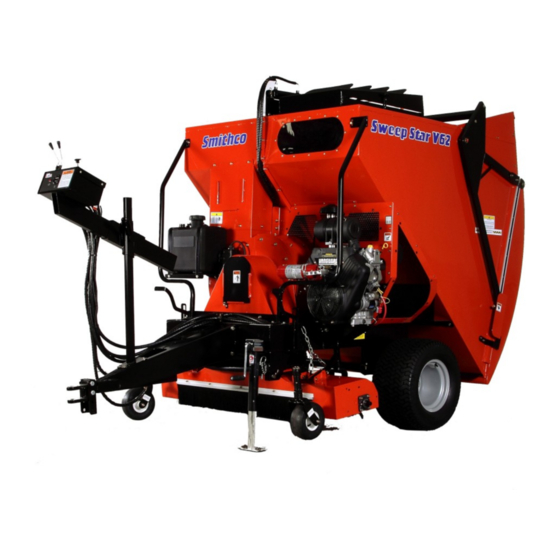
Summary of Contents for Smithco SweepStar V62
- Page 1 Parts & Service SweepStar V62 with Electric Clutch 78-200 SN: 78595 January 2012 Product Support: Hwy SS & Poplar Ave; Cameron WI 54822 1-800-891-9435 productsupport@smithco.com...
-
Page 2: Table Of Contents
CONTENTS Introduction .......... 1-10 Introduction ................... 1-3 Safe Practices ................2 Specifications ................3 Optional Equipment ..............3 Service ..................4-11 Maintenance ................4-6 Overloading Debris Hopper and Vacuum Housing Wear ....7 Service Chart ................8-9 Adjustments ................10 Tailgate Adjustments .............. -
Page 3: Introduction
All Smithco Smithco Smithco Smithco machines have a Serial Number and Model Number. Both numbers are needed when ordering Smithco parts. Refer to engine manual for placement of engine serial number. For product and accessory information, help finding a dealer, or to register your procuct please contact us at www.Smithco.com. -
Page 4: Safe Practices
17. Stop engine before making repairs/adjustments or checking/adding oil to the crankcase. 18. Use parts and materials supplied by SMITHCO only. Do not modify any function or part. 19. Do not remove the radiator cap when the engine is hot. When cooled, loosen cap slightly to the stop to relieve any pressure before removing the cap completely. -
Page 5: Specifications
SPECIFICATIONS FOR SWEEP STAR V62 WEIGHTS AND DIMENSIONS Length 151" (384 cm) Width 68" (172 cm) Height 87" (221 cm) Weight 1500 lb (680 kg) SOUND LEVEL At ear level 98 dBA At 30 ft (9.14m) 92.5 dBA ENGINE Make Briggs &Stratton Model# 543477... -
Page 6: Service
MAINTENANCE Before servicing or making adjustments to machine, stop engine and remove key from ignition. Use all procedures and parts prescribed by the manufacturer's. Read the engine manual before operation. LUBRICATION Use No. 2 General Purpose Lithium Base Grease and lubricate every 100 hours. The Sweep Star V62 has sev- enteen grease fittings. - Page 7 MAINTENANCE (CONTINUED) TIRE PRESSURE Caution must be used when inflating a low tire to recommended pressure. Over inflating can cause tires to explode. Tires on the machine should be 18 psi (1.3 bar), castor wheels should be 20 psi (1.4 bar). Improper inflation will reduce tire life considerably.
- Page 8 MAINTENANCE (CONTINUED) BATTERY Batteries normally produce explosive gases which can cause personal injury. Do not allow flames, sparks or any ignited object to come near the battery. When charging or working near battery, always shield your eyes and always provide proper ventilation. Battery cable should be disconnected before using “Fast Charge”.
-
Page 9: Overloading Debris Hopper And Vacuum Housing Wear
40 in. (101 cm) VACUUM HOUSING WEAR Smithco Sweeper-Vacs are fitted with a wear resistant liner in the vacuum housing. This will provide additional housing life. Be sure the following points are explained to the user: 1. The vacuum housing and impeller must be cleaned each time the unit is used so the housing liner is inspected daily. -
Page 10: Service Chart
SERVICE CHART Before servicing or making adjustments to the machine, stop engine, set park break, block wheels and remove key from ignition. Follow all procedures and ONLY use parts prescribed by the manufacturer. Read the engine manual before maintenance. The suggested maintenance checklist is not offered as a replacement for the manufacturer’s engine manual but as a supplement. - Page 11 SERVICE CHART Maintenance Service Interval Maintenance Procedure Torque the wheel lug nuts. (64-74 ft/lb (87-100 Nm)) After the first 8 operating hours Change the engine oil filter. Check the engine oil level. Clean area around muffler and controls. Check the hydraulic fluid level. Before each use daily Check the tire pressure.
-
Page 12: Adjustments
ADJUSTMENTS ADJUSTMENT OF BELT TENSIONER There are two belt tensioners on the Sweep Star V62. One controls the tension on the belt from the engine to blower shaft the other controls the belt on the finger or brush reel. The proper tension of the idler should be 12 to 15 as per the gauge (A) on the side of the tightener. -
Page 13: Tailgate Adjustments
TAILGATE ADJUSTMENT V62 TAILGATE LEVELING If the tailgate is not sitting level against the hopper it can be leveled by loosening the inch bolts that hold the pivot bracket to the upper lift arms then rotate the pivot brackets until tailgate level then tighten. Once it is level it must be readjusted using steps 1, 2 and 3. -
Page 14: Diagrams
WIRING DRAWING... -
Page 15: Wiring Schematic
WIRING PARTS LIST REF# PART# DESCRIPTION QUANTITY 78-368 Electric Clutch 15-314 Toggle Switch 15-472 Switch Boot 12-017 Hour Meter 13-488 Ignition Switch 50-359 Oil Light 8874 Female Bullet Connector 8875 Male Bullet Connector 8963 Heat Shrink Plug on Engine 8975 30 Amp Circuit Breaker 8977 Circuit Breaker Boot... - Page 16 HYDRAULIC DRAWING...
- Page 17 HYDRAULIC PARTS LIST REF# PART# DESCRIPTION QUANTITY 78-247 Hydraulic Hose (brush motor to valve) 78-413 Hydraulic Pump 23-006 Oil Filter 23-031 Filter Element (replacement only) 78-249 Hydraulic Hose (pump to valve) 78-250 Hydraulic Hose (return to tank ) 78-415 2-Bank Hydraulic Valve 78-246 Hydraulic Hose (rear hyd.
-
Page 18: Parts
BODY AND FRAME DRAWING... -
Page 19: Body And Frame
BODY AND FRAME PARTS LIST REF# PART# DESCRIPTION QUANTITY HSTP-14-20-075 Phillips Truss Head Machine Screw - 20 x 78-253 Right Guard 78-274 Cage Nuts 78-315 Right Guard Mount 78-274 Cage Nuts HBFL-516-18-075 Flange Bolt - 18 x HNFL-516-18 Flange Whiz Lock Nut - 18 HBFL-516-18-075 Flange Bolt... - Page 20 ENGINE AND CONTROLS DRAWING...
-
Page 21: Engine And Controls
ENGINE AND CONTROLS PARTS LIST REF# PART# DESCRIPTION QUANTITY HSM-10-32-063 Machine Screw #10 - 32 x HWL-10 Lockwasher #10 HNFL-10-32 Flange Whiz Lock Nut #10 - 32 34-159 Throttle Mounting Bracket HSM-10-32-063 Machine Screw #10 - 32 x HWL-10 Lockwasher #10 HN-10-32 Flange Whiz Lock Nut #10 - 32 78-446... - Page 22 PULLEY AND PUMP DRAWING...
-
Page 23: Pulley And Pump
PULLEY AND PUMP PARTS LIST REF# PART# DESCRIPTION QUANTITY HB-12-13-250 Bolt - 13 x 2 (part of 78-224) HMB-12-14 Machine Bushing - 14GA 76-275 Spacer (part of 78-224) HNCL-12-13 Center Lock Nut - 13 (part of 78-224) 16-013 Idler Pulley 78-224 Belt Tensioner HBM-10-1.5-30... - Page 24 BLOWER AND VACUUM HOUSING DRAWING...
-
Page 25: Blower And Vacuum Housing
BLOWER AND VACUUM HOUSING PARTS LIST REF# PART# DESCRIPTION QUANTITY 15-838 6 Gal CARB Gas Tank (includes * items) 73-050 Gas Cap (replacement only) Neck Vent Port 8800-78 Fuel Hose x 78" 18-186 Hose Clamp 78-439 Trap Door 78-403 Trap Door Lining 8828-19 Foam tape 19"... -
Page 26: Finger Reel
FINGER REEL DRAWING... - Page 27 FINGER REEL PARTS LIST REF# PART# DESCRIPTION QUANTITY HMB-58-14 Machine Bushing x 14GA HN-58-11 - 11 HB-58-11-300 Bolt - 11 x 3 HNTL-58-11 Lock Nut - 11 HG-14-28-180 Grease Fitting - 28 x 180° 78-241 Chain Connector 78-284 Left Hand Deck Lift 20-018 Bushing (part of 78-284)
-
Page 28: Brush Reel
BRUSH REEL DRAWING... - Page 29 BRUSH REEL PARTS LIST REF# PART# DESCRIPTION QUANTITY HMB-58-14 Machine Bushing x 14GA HN-58-11 - 11 HB-58-11-300 Bolt - 11 x 3 HNTL-58-11 Lock Nut - 11 HG-14-28-180 Grease Fitting - 28 x 180° 78-241 Chain Connector 78-284 Left Hand Deck Lift 20-018 Bushing (part of 78-284)
-
Page 30: Reel And Hydraulic Pump
REEL & HYDRAULIC PUMP DRAWING... - Page 31 REEL & HYDRAULIC PUMP PARTS LIST REF# PART# DESCRIPTION QUANTITY 18-240 Pipe Adapter 78-228 Coupler " 78-229 Nipple " 18-334 Nipple 18-009 Elbow 18-333 Adapter HWK-316-063 Woodruff key 78-259 Hydraulic Motor Mount HB-38-16-150 Bolt - 16 x 1 HNFL-38-16 Flange Whiz Lock Nut - 16 78-424 Pulley...
- Page 32 HOPPER DRAWING...
-
Page 33: Hopper
HOPPER PARTS LIST REF# PART# DESCRIPTION QUANTITY 78-305 Filter Insert HBFL-516-18-075 Flange Bolt - 18 x HNFL-516-18 Flange Whiz Lock Nut - 18 78-272 Hopper Cover 78-395 Filter Hood HB-14-20-125 Bolt - 20 x 1 HNFL-14-20 Flange Whiz Lock Nut - 20 78-384 Flex Draw Latch... - Page 34 HOPPER DRAWING...
- Page 35 HOPPER PARTS LIST REF# PART# DESCRIPTION QUANTITY HMB-34-10 Machine Bushing x 10GA HP-18-150 Cotter Pin 78-319 Tailgate Adjustment HB-38-16-175 Bolt - 16 x 1 HNFL-38-16 Flange Whiz Lock Nut 78-383 Left Hopper 78-394 Filter Case 78-386 Hopper Filter 78-382 Screen 78-385 Wear Strip Bracket 8946-42...
- Page 36 78-415 2-BANK VALVE DRAWING...
-
Page 37: 78-415 2-Bank Hydraulic Valve
78-415 2-BANK VALVE PARTS LIST REF# PART# DESCRIPTION QUANTITY 78-415-01 Body (complete with spacer and check valve) 78-415-02 Spool HDM10 78-415-03 O-Ring Seal 78-415-04 Flanged Washer HDM10 78-415-05 Spacer 78-415-06 A Type Spool HDS11 78-415-07 Positioner 78-415-08 Plug 78-415-09 Lever Group HDS11 78-415-10 Metric Socket Screw M5 x .8 x 45 78-415-11... -
Page 38: Rear Axle / Electric Brake
REAR AXLE / ELECTRIC BRAKE PARTS LIST... - Page 39 REAR AXLE / ELECTRIC BRAKE PARTS LIST REF# PART# DESCRIPTION QUANTITY 78-216 Axle Complete 78-216-02 Grease Seal 78-406 Hub Assembly (includes all * items) HP-18-200 Cotter Pin 78-119 Bearing Cup and Cone HNAR-100-14 Slotted Jam Nut 1 - 14 80-167 Grease Cap HNL-12-20 Lug Nut 1/2 - 20...
-
Page 40: Accessories
78-201 REPLACEMENT BRUSH REEL DRAWING 78-202 REPLACEMENT FINGER REEL DRAWING... - Page 41 78-201 REPLACEMENT BRUSH REEL PARTS LIST REF# PART# DESCRIPTION QUANTITY 78-222 Mounted Bearing HB-38-16-125 Bolt - 16 x 1 HNFL-38-16 Flange Whiz Lock Nut - 16 HG-14-28-180 Grease Fitting -20 x 180° (comes with 78-222) 78-348 Spiral Brush Shaft HKSQ-14-100 Machine Key 78-321 Spiral Brush...
-
Page 42: 78-205 Remote Vacuum Hose
78-205 REMOTE VACUUM HOSE DRAWING... - Page 43 78-205 REMOTE VACUUM HOSE PARTS LIST REF# PART# DESCRIPTION QUANTITY HBFL-516-18-075 Flange Bolt - 18 x HNFL-516-18 Flange Whiz Lock Nut - 18 78-318 Hose Rack HBFL-516-18-075 Flange Bolt - 18 x (part of machine) HNFL-516-18 Flange Whiz Lock Nut - 18 (part of machine) 78-314...
-
Page 44: 78-204 5 Th Wheel Hitch
78-204 5 WHEEL HITCH DRAWING Do not tow on public roads. - Page 45 78-204 5 WHEEL HITCH PARTS LIST REF# PART# DESCRIPTION QUANTITY HB-516-18-100 Bolt - 18 x 1 HNTL-516-18 Lock Nut - 18 HB-38-16-225 Bolt - 16 x 2 78-352 Control Panel Mount HST-14-20-075 Truss Head Machine Screw - 20 x (part of machine) HNFL-14-20 Flange Whiz Lock Nut - 20...
-
Page 46: 78-206 Clevis Hitch
78-206 CLEVIS HITCH DRAWING... - Page 47 78-206 CLEVIS HITCH PARTS LIST REF# PART# DESCRIPTION QUANTITY 78-244 " Clevis 78-268 Hitch Insert 78-267 Tongue HB-12-13-350 Bolt - 13 x 3 HNTL-12-13 Lock Nut - 13 HBFL-516-18-075 Flange Bolt -18 x HNFL-516-18 Flange Whiz Lock Nut 78-299 Adjustment Slide 78-295 Adjustment Lock 15-020...
-
Page 48: 78-209 Ball Hitch
78-209 BALL HITCH DRAWING... - Page 49 78-209 BALL HITCH PARTS LIST REF# PART# DESCRIPTION QUANTITY 78-356 2" Ball Coupler 78-268 Hitch Insert 78-267 Tongue HBFL-516-18-075 Flange Bolt -18 x HNFL-516-18 Flange Whiz Lock Nut 78-299 Adjustment Slide 78-295 Adjustment Lock 15-020 Hand Grip 78-298 Control Panel Adjustment 78-312 Control Panel Mount HST-14-20-075...
-
Page 50: 78-207 Hydraulic Lift Kit
78-207 HYDRAULIC LIFT KIT DRAWING... - Page 51 78-207 HYDRAULIC LIFT KIT PARTS LIST REF# PART# DESCRIPTION QUANTITY HB-38-16-100 Bolt - 16 x 1 HNFL-38-16 Whiz Lock Nut - 16 HB-58-11-200 Bolt - 11 x 2 HNTL-58-11 Lock Nut - 11 HCP-12-150 Clevis Pin 78-357 Right Hydraulic Lift Mount 18-223 Flange Bushing (part of 78-357)
-
Page 52: 78-416 3-Bank Hydraulic Valve
78-416 3 - BANK HYDRAULIC VALVE DRAWING... - Page 53 78-416 3 - BANK HYDRAULIC VALVE PARTS LIST REF# PART# DESCRIPTION QUANTITY 78-416-01 Body (complete with spacer and check valve) 78-415-02 Spool HDM10 78-415-03 O-Ring Seal 78-415-04 Flanged Washer HDM10 78-415-05 Spacer 78-415-06 A Type Spool HDS11 78-415-11 Positioner HDM10 78-415-08 Plug 78-415-09...
-
Page 54: 78-208 Filter System
78-208 FILTER SYSTEM DRAWING... - Page 55 78-208 FILTER SYSTEM PARTS LIST REF# PART# DESCRIPTION QUANTITY 78-288 Filter Case 78-328 Filter...
-
Page 56: 78-210 & 78-211 Reel And Hydraulic Pump
78-210 &78-211 REEL AND HYDRAULIC PUMP DRAWING... - Page 57 78-210 &78-211 REEL AND HYDRAULIC PUMP DRAWING REF# PART# DESCRIPTION QUANTITY 18-240 Pipe Adapter 78-228 Coupler " 78-229 Nipple " 18-334 Nipple 18-009 Elbow 18-333 Adapter HWK-316-063 Woodruff key 78-259 Hydraulic Motor Mount HB-38-16-150 Bolt - 16 x 1 HNFL-38-16 Flange Whiz Lock Nut - 16 78-424...
-
Page 58: 78-210 Nylon Brush Head
78-210 NYLON BRUSH HEAD DRAWING... - Page 59 78-210 NYLON BRUSH HEAD PARTS LIST REF# PART# DESCRIPTION QUANTITY HB-14-20-075 Bolt - 20 x HNFL-14-20 Flange Whiz Lock Nut - 20 78-344 Strip Brush Holder (drilled) HB-12-13-600 Bolt - 13 x 6 78-322 Strip Brush 33-338 Axle Bearing 78-393 Castor Arm HB-38-16-250 Bolt...
-
Page 60: 78-211 Rubber Finger Head
78-211 RUBBER FINGER HEAD DRAWING... - Page 61 78-211 RUBBER FINGER HEAD PARTS LIST REF# PART# DESCRIPTION QUANTITY HB-14-20-075 Bolt - 20 x HNFL-14-20 Flange Whiz Lock Nut - 20 78-344 Strip Brush Holder (drilled) HB-12-13-600 Bolt -13 x 6 78-322 Strip Brush 42-202 Tire & Wheel 33-338 Axle Bearing HNTL-12-13 Lock Nut...
- Page 62 NOTES...
-
Page 63: Reference
25-355 Decal, Tire Pressure Rear Wheels (18 psi) 25-356 Decal, Tire Pressure Castor Forks (20 psi) 25-359 Decal, Smithco Front Chute & Rear Tailgate (3.25 x 17.312) 25-361 Decal, Technical Assistace Main Frmae 25-362 Decal, Danger Fire Hopper Front 25-363 Decal, Max. -
Page 64: Quick Reference Replacement Parts
QUICK REFERENCE REPLACEMENT FILTERS 23-031 Hydraulic Oil Filter Element 50-403 In-Line Fuel Filter 76-487 Engine Oil Filter Briggs# 842921 REPLACEMENT BELTS 78-443 3-V Belt SEAL KITS 78-414 Hydraulic Motor (reel) 72-186-01 Seal Kit 14-534 Hydraulic Cylinder (Lift Kit) 14-529 Seal Kit 15-839 Tailgate Cylinder 14-531... -
Page 65: Warranty
30 days from discovery of the condition. If you need help locating an Authorized Smithco Distributor, or if you have questions regarding your warranty rights or responsibilities, you may contact us at: Smithco Product Support Department 200 West Poplar Ave. - Page 66 Smithco may require the return of failed parts or components in order to determine the validity of any warranty claim. Smithco will not be obligated to replace components of other manufacturers if inspection by the original component manufacturer indicates that failure was due to normal wear and tear, expected consumption through use or improper care or service.
Need help?
Do you have a question about the SweepStar V62 and is the answer not in the manual?
Questions and answers