Sign In
Upload
Manuals
Brands
LSIS Manuals
Controller
XGR-DBDF
LSIS XGR-DBDF PLC Controller Manuals
Manuals and User Guides for LSIS XGR-DBDF PLC Controller. We have
1
LSIS XGR-DBDF PLC Controller manual available for free PDF download: User Manual
LSIS XGR-DBDF User Manual (267 pages)
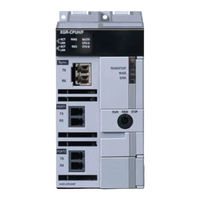
Programmable Logic Controller, CPU Module
Brand:
LSIS
| Category:
Controller
| Size: 5 MB
Table of Contents
Table of Contents
11
About this User Manual
17
Configuration of the XGR Redundant System
19
Features of the XGR Redundancy System
20
Glossary
22
Chapter 1 Overview
17
Chapter 2 System Configuration
25
Chapter 3 General Specifications
43
Chapter 4 CPU Module
44
Chapter 5 Program Constitution and Operation Method
52
Program Basics
52
Program Structure and Execution
52
Operation of Instantaneous Interrupt
56
Scan Time
57
Performance Specifications
44
Names and Functions of Parts
46
Battery
50
Battery Life
50
Battery Specifications
50
Cautions for Usage
50
Replacement
51
Product List
25
Redundancy System
31
Redundant System Configuration
31
Redundancy of CPU System
35
Extension Base Communication Path Redundancy
36
Extension Drive Redundancy
36
Power Module Redundancy
36
Example of Redundant System Configuration
38
Network System
41
Networking Among Systems
41
Remote I/O System
41
General Specifications
43
Scan Time
59
Program Execution
62
Program Type
62
Restart Mode
63
Task Program
65
Operation Mode
74
RUN Mode
74
Stop Mode
75
Debug Mode
76
Switching Operation Mode
76
Redundancy System Operation
78
Start-Up of Redundant System
80
Memory
82
Program Memory
82
Data Memory
83
Data Retain Area Setting
83
Performance Specifications
109
Identification and Function
110
Type and Specification
112
Parts' Names
113
Selection
114
Examples of Current Consumption/Power Calculations
115
Scan Watchdog Timer
85
Self-Diagnosis Function
85
Battery Level Check
87
I/O Module Check Function
87
Saving Error Log
87
Troubleshooting
87
Clock Function
88
Remote Functions
91
Force I/O Setting
94
Forced On/Off Function of I/O
94
The Point of Time of Method of Forced On/Off Process
95
Error History
96
Mode Change History
96
Operation History Saving Function
96
Shut down History
96
System History
96
External Device Failure Diagnosis Function
97
Operation Mode Setting
98
Data Synchronization Area Setting
100
Setting Operation of Communication
101
Global Status Variable
102
ONE IP Solution
102
Applications and Operations
104
Fault Mask Function
104
Fault Mask Setting
104
Releasing Fault Mask
104
Applications and Operations
105
I/O Module Skip Function
105
Releasing Skip Function
105
Setting and Processing I/O Data
105
I/O Base Skip Function
106
Purpose and Outline of the Operation
106
Releasing Skip Function
106
Setting Method
106
Module Replacement Function During Operation
107
Module Replacement in Redundant System
107
Replacing I/O Module in Redundant System
107
Replacing Base Module in Redundant System
108
Chapter 6 CPU Module Functions
85
Chapter 7 Extension Drive Module
109
Chapter 8 Power Module
112
Cautions for Selecting Modules
117
Chapter 9 IO Module
117
Digital Input Module Specifications
119
Point DC24V Input Module(Source/Sink Type)
119
Point DC24V Input Module(Source/Sink Type)
120
Point DC24V Input Module(Source Type)
121
Point DC24V Input Module(Source/Sink Type)
122
Point DC24V Input Module(Source Type)
123
Point DC24V Input Module(Source/Sink Type)
124
Point DC24V Input Module(Source Type)
125
Point AC110V Input Module
126
Point AC220V Input Module
127
Point AC220V Isolated Input Module
128
Point Relay Output Module
129
Point Relay Output Module
130
Point Relay Output Module(Surge Killer Built-In Type)
131
Point Triac Output Module
132
Point Transistor Output Module(Sink Type)
133
Point Transistor Output Module(Sink Type)
135
Point Transistor Output Module(Source Type)
136
Point Transistor Output Module(Source Type)
137
Point Transistor Output Module(Source Type)
138
Point Transistor Isolated Output Module(Sink Type)
139
Digital I/O Combined Module Specifications
140
Point(DC Input Transistor Output) I/O Combined Module
140
Event Input Module
141
Modules Accessible to Smart Link
142
Smart Link Components
142
Smart Link Connection
143
Smart Link Mapping Table
143
Smart Link Connection Diagram
144
Smart Link Specifications & Dimensions
154
Chapter 10 Base and Extension Cable
155
Specifications
155
Basic Base
157
Sync. Cable
158
Basic Base
160
Parts and Names
160
Chapter 11 Installation and Wiring
162
Installation
162
Installation Environment
162
Cautions for Handling
164
Attachment/Detachment of Modules
169
Power Wiring
171
Wiring
171
I/O Device Wiring
172
Grounding Wiring
173
Specifications of Wiring Cable
174
Grounding
174
Chapter 12 Maintenance
175
Chapter 13 EMC Compliance
177
Chapter 14 Built-In PID Function
181
Basic Troubleshooting Procedure
218
Chapter 15 Troubleshooting
218
Troubleshooting
219
Action When POWER LED Is off
220
Action When WAR. (Warning) LED Is on
221
Action When ERR. LED Is on
225
Action When RUN/STOP LED Is off
226
Acton When I/O Module Does Not Work Properly
227
Action When Writing Program Is Not Possible
229
Action When Sync. Cable Is Not Installed Properly
230
When Undesirable Master Switching Occurs
231
When Newly Added CPU Does Not Join Redundant Operation
232
When Failing to Switch Master
233
Troubleshooting Questionnaires
238
Cases
239
Trouble Types and Measures of Input Circuit
239
Trouble Types and Measures of Output Circuit
240
Error Codes During CPU Operation
242
Error Codes List
242
Appendix 1 Flags List
245
Appendix 1.1 User Flag
245
Appendix 1.2 System Error Representative Flag
246
Appendix 1.3 System Error Detail Flag
250
Appendix 1.4 System Warning Representative Flag
252
Appendix 1.5 System Warning Detail Flag
254
Appendix 1.6 System Operation Status Information Flag
255
Appendix 1.7 Redundant Operation Mode Information Flag
260
Appendix 1.8 Operation Result Information Flag
261
Appendix 1.9 Operation Mode Key Status Flag
262
Appendix 1.10 Link Flag (L) List
263
Appendix 1.11 Reserved Word
265
Features
181
PID Control
181
PID Control Operation
182
PID Equation
182
Terms Used
182
P Control
183
PI Control
184
PID Control
185
PID Instruction
186
PID Loop State
186
PID Instruction Group
187
Common Bit Area
192
Individual Data Operation
195
Convenient Functions of PID Instruction
202
Operation and Function of Auto-Tuning
202
Operation and Function of Cascade
203
Directions of PID Instructions
204
Hardware Configuration
204
Program Example 1
207
PID Control
208
At(Auto-Tuning) Operation
215
Program Example 2
216
Cascade Operation
217
EMC Specifications
177
Requirements Complying with EMC Specifications
177
Panel
178
Cable
179
Requirements Complying with Low Voltage Direction
180
Selection of XGT Series PLC
180
Specifications Applicable to XGT Series
180
Repairs and Maintenance
175
Routine Inspection
175
Periodic Inspection
176
Advertisement
Advertisement
Related Products
LSIS XGR Series
LSIS XGR-CPUH/F
LSIS XGR-CPUH/T
LSIS XGR-DBST
LSIS XGR-DBSF
LSIS XGR-DBSFS
LSIS XGR-DBDT
LSIS XGR-DBSH
LSIS XGR-DBDH
LSIS XGR-CPUH/S
LSIS Categories
Controller
Inverter
Control Unit
DC Drives
Relays
More LSIS Manuals
Login
Sign In
OR
Sign in with Facebook
Sign in with Google
Upload manual
Upload from disk
Upload from URL