
Related Manuals for DayTronic 4000 Series


Summary of Contents for DayTronic 4000 Series
- Page 1 SB.2 MODEL 4078 SINGLE-CHANNEL AC STRAIN GAGE INSTRUMENT INSTRUCTION MANUAL 4000 Instrument Series...
- Page 2 No part of this document may be reprinted, reproduced, or used in any form or by any electronic, mechanical, or other means, including photocopying and recording, or in any information storage and retrieval system, without permission in writing from Daytronic Corporation. All specifications are subject to change without notice.
- Page 3 Model 4078 Instruction Manual, v. SB.2 Pub. No. 4078.2, Issued 10/96 Part No. 91630 MODEL 4078 SINGLE-CHANNEL AC STRAIN GAGE INSTRUMENT INSTRUCTION MANUAL Daytronic Corporation Dayton, OH 45439-1521 www.daytronic.com...
-
Page 5: Table Of Contents
Contents Section Page 1. Introduction a. Description and Specifications ..........1.1 b. Physical Layout ..............1.5 c. Panel Mounting ..............1.7 d. Standard Channel Configuration .......... 1.8 e. Standard Logic Configuration ..........1.9 Using the Front-Panel Setup Buttons ......... 1.11 g. -
Page 6: Description And Specifications
Model 4078 Description and Specifications General 4078 Features Transducer Input(s) Real-Time Signal A to D Math Conditioning Conversion Processing + – x ÷ √ • Excitation • 16-bit (±32000 count) • • "y = mx + b" scaling • Optional internal •... - Page 7 PUSH BUTTONS. A full listing of your 4078's standard configuration is given in Appendix A. Like all 4000 Series instruments, however, the 4078 can be rapidly and easily reprogrammed in the field, to provide a variety of unique application solutions. For such reprogramming you can use either •...
- Page 8 4078. These commands may also be issued directly to the 4078 via the optional Extended Keyboard. Commands which are common to all 4000 Series models are described in detail in the optional 4000 Series System Instruction Manual . IT IS RECOM-...
- Page 9 Model 4078 Description and Specifications I/O—see Appendix A of the 4000 Series System Instruction Manual) : Transducer Types and Ranges: The 4078 accepts a force- measurement signal from a conventional strain gage transducer with 4-arm bridge of nominal 350 ohms or higher, and a full scale range of 0.75, 1.50, or 3.00 mV/V.
-
Page 10: Physical Layout
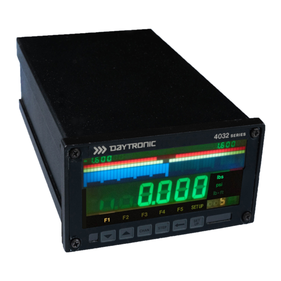
Physical Layout Study the following diagrams to acquaint yourself with your 4078's most important front and rear elements. Fig. 1 4078 Front Panel "Low-Low" Limit "High-High" Limit (LLL) (HHL) Bargraph Bargraph Low Endpoint "Low" Limit "High" Limit High Endpoint (LEP) (LOL) (HIL) (HEP) - Page 11 Physical Layout Fig. 2 4078 Rear Panel Analog Output SYMMETRY CONDITIONER Connector ADJUSTMENT CONNECTOR (see Fig. 10) CONTROL —attaches to 4078 PHASE ON-OFF Analog Input Board AC Power ADJUSTMENT Switch (see Figs. 5-7) Fuse Connector CONTROL Voltage Panel- Connector Logic I/O RS-232-C Selector Mount...
-
Page 12: Panel Mounting
Panel Mounting You can easily mount a Model 4078 in your own precut panel. Cutout dimensions for a panel-mounted unit are standard DIN (see Fig. 3); panel thickness should not exceed 6 mm (0.24 in). When mounting a 4078, DO NOT REMOVE THE FRONT BEZEL. Simply unscrew the two rear-panel CLAMP SCREWS and slide the CLAMP SLIDES rearwards out of their grooves. -
Page 13: Standard Channel Configuration
Standard Channel Configuration Channel No. Channel Function "LIVE" INPUT CHANNEL This channel represents the 4078's conditioned analog input . Sensor calibration is performed on this channel, as explained in Section 2.e and Appendix F. THIS CHANNEL IS NOT TO BE USED FOR THE 4078 "LIVE"... -
Page 14: Standard Logic Configuration
Standard Logic Configuration Your 4078 provides eight logic input/output bits in open-collector, negative-true form, where the "Logic 1" state is defined as nominal 0 V-DC and "Logic 0" as nominal +5 V-DC. The standard logic I/O configuration is shown in Fig. 4, below, with reference to the 10-terminal Logic I/O Connector on the rear of the 4078. - Page 15 Standard Logic Configuration Bit No. Logic Function "BELOW BARGRAPH" VIOLATION OUTPUT Terminal 0 will be at a Logic 1 (0 V-DC) level whenever the reading of Channel 5 is less than the current "LEP" value for that channel. "LOW LOW" VIOLATION OUTPUT Terminal 1 will be at a Logic 1 (0 V-DC) level whenever the reading of Channel 5 is less than the current "LLL"...
-
Page 16: Using The Front-Panel Setup Buttons
Using the Front-Panel Setup Buttons Study this manual section carefully to familiarize yourself with the general operation of your 4078's front-panel buttons when they are in "SETUP" mode. Specific setup parameters—such as "HIGH END- POINT (HEP)", "FILTER (FIL)," "LCD," etc.—are explained in detail in Section 2. - Page 17 Using the Front-Panel Setup Buttons Each of the six buttons will now assume its "SETUP" function, as designated by the actual button label (for each button's "RUN- TIME" function, see Section 3.) The small mnemonic display under the 4078's unit legends will alternately read "DIS" and the number of the channel that was on display when you pushed the SETUP button.
- Page 18 Using the Front-Panel Setup Buttons —at which point you can, if desired, move to any other channel via the UP/DOWN ARROW buttons, as above. 3. Stepping Through a Channel's Parameter List A given channel's configuration sequence includes the parameters listed on the next page. These will appear as mnemonics under the unit-legend display.
- Page 19 Using the Front-Panel Setup Buttons To move to the next parameter in sequence, STEP PRESS THE BUTTON As each parameter appears, you have the option of leaving it as it is and stepping to the next one by again pressing STEP, or of modifying its value by means of the "ARROW"...
- Page 20 Using the Front-Panel Setup Buttons In the negative realm , these buttons seem at first glance to function backwards. Thus, if the displayed parameter is preceded by a minus sign, then "increasing" the active digit by "1"—as a result of pressing the UP ARROW button—means decreasing that digit's absolute value by "1."...
- Page 21 Using the Front-Panel Setup Buttons NOTE: The above procedure will change the original values of one or more digits to the right of the most significant digit , except in the case where they are all originally zero. Therefore, you will most likely have to go back and reset these digits, using the LEFT ARROW and UP/DOWN ARROW buttons as explained in Step 5.
-
Page 22: Low Battery Warning
Low Battery Warning The 4078 is equipped with an internal 3-V lithium battery. This battery is necessary to maintain the instrument's DATA RAM and to retain factory-entered analog alignment values required for accurate calibration. Data retention is guaranteed down to a battery level of 2.2 V-DC. -
Page 23: Transducer Cabling
Transducer Cabling The Model 4078's Analog Input Board mates with Daytronic CONDI- TIONER CONNECTOR No. 60322, which allows direct solder-terminal attachment of cable leads. The connector's internal solder terminals are labelled 1 through 10 and A through L. The connector is "keyed" by small plastic inserts embedded between certain terminal-pin pairs, each of which matches a slot in the 4078's rear Analog Input Board. - Page 24 Transducer Cabling CONDITIONER CONNECTOR (No. 60322) +EXCITATION –SENSE +SENSE +SIGNAL –SIGNAL CAL SENSE –EXCITATION Fig. 5(a) Model 4078 Transducer Cabling: SHIELD Ground Lug 4-Wire Strain Gage Cabling (under 20 ft. in length) Connector pins shown as viewed from rear (cable) side of connector. the optional external SHUNT RESISTOR line from Pin 5—is tied to the +SIGNAL line at the CONDITIONER CONNECTOR.
- Page 25 Transducer Cabling CONDITIONER CONNECTOR +SENSE (No. 60322) +EXCITATION +SIGNAL –SIGNAL CAL SENSE –EXCITATION –SENSE Unconnected wire (Paired with "CAL SENSE") SHIELD Ground Lug Fig. 5(b) Connector pins shown as viewed from rear (cable) side of connector. Model 4078 Transducer Cabling: 8-Wire Strain Gage Cabling (20 ft.
- Page 26 Transducer Cabling be shielded in four pairs, as shown in the figure, with the shield open at the transducer end. Also note that • SENSE and EXCITATION lines should be tied at the transducer . • The 4078's Pin 5 ("LEBOW CAL") is to be connected to the "CAL" pin on the Lebow sensor (Pin 4 is not used in this case).
-
Page 27: Powerup
Powerup ---------- PLEASE NOTE ---------- EVERY TIME YOU POWERUP YOUR MODEL 4078, ALLOW A NOMINAL 15 SECONDS FOR VALID DATA AND SETUP VALUES TO BE ESTABLISHED. ALSO NOTE: Since setup entries are automatically saved to nonvolatile memory, your 4078 will always powerup to the same setup and display configuration that existed when it was last powered down. - Page 28 Powerup connector is ground. THE INSTRUMENT MUST BE PROPERLY GROUNDED. To safely operate from a two-contact outlet, use a 3- prong-to-2-prong adaptor and connect the green pigtail on the adaptor to earth ground. Since the presence of electrical noise can affect the ultimate integrity of your data, the noise level should be suppressed as much as possible.
-
Page 29: Adjusting Lcd Viewing Angle
Adjusting LCD Viewing Angle You can easily optimize your 4078's LCD DIGITAL DISPLAY for your particular viewing angle . Following the procedure given in Section 1.f, above, press the instrument's front-panel SETUP key, and then "step" to the "LCD" parameter (the letters "LCd" should appear in the digital display, to indicate that the instrument is in "LCD adjustment"... -
Page 30: Selecting A Channel For Display
Selecting a Channel for Display Your 4078's "Standard Channel Configuration" was given in Section 1.d, above. To cause the current "live" reading of any channel—either "scanned" or "unscanned"—to be displayed on both the DIGITAL and BARGRAPH displays, you need only PRESS THE BUTTON PRESS THE... -
Page 31: Channel Calibration
(SHUNT)" calibration, see Appendix F. For use of the 4078's internal LINEARIZATION TABLES (for a nonlinear input), and for a discussion of "y = mx + b" calibration theory, see the optional 4000 Series System Instruction Manual . Before you calibrate your 4078 for the first time, you should perform the following PHASE AND SYMMETRY ADJUSTMENT procedure.* Once... - Page 32 Channel Calibration (where [CR] is the CARRIAGE RETURN that terminates the command). 5. Now switch in the internal shunt resistor for a positive up-scale reading of Channel 1 by entering a SHUNT CALIBRATE— POSITIVE command of SHP 1 = ON [CR] 6.
- Page 33 Channel Calibration 14. Apply a second accurately known value of input loading—a value (positive or negative) from 80% to 100% of the transducer's nominal full-scale rating. 15. Now enter the numerical value of the second known input, with appropriate polarity. This "forces" the channel's data reading to equal this value, thereby determining the SCALING FACTOR to be applied to all subsequent channel readings.
-
Page 34: Setting Channel Filter
Setting Channel Filter In addition to the normal-mode analog filtering applied to the Model 4078's "live" input channel (No. 2), digital filtering is also provided, with smoothing constants selectable via the front panel. The effect of the digital filter is to remove small unwanted dynamic signal components, while allowing large-scale fluctuations to pass unaffected. -
Page 35: Scaling The Bargraph Display
Scaling the Bargraph Display After calibrating your 4078's "live" input channel (No. 2), you should set the high and low endpoints for the individual BARGRAPH display of Channel 5 ("LIVE" INPUT WITH TARE), using the procedure given below. This same procedure may be used to scale the bargraph dis- play of any of the other 4078 data channels listed in Section 1.d. - Page 36 Scaling the Bargraph Display less than the "HEP" value. At least 51 units (absolute count) must separate the HEP and LEP values. NOTE, however, that the 4078's front panel furnishes a "truncated" numeric display of the two endpoint values of the currently displayed bargraph (see Fig.
-
Page 37: Defining Limit Zones
Defining Limit Zones Once you have set the endpoints of the respective bargraph display for Channel 5, you can define seven discrete limit zones for the bargraph, as shown in Fig. 8: "BELOW BARGRAPH" ZONE (less than LEP); LOWER "DANGER" ZONE (LEP to LLL); LOWER "CAUTION" ZONE (LLL to LOL);... -
Page 38: Logic I/O Connections
Defining Limit Zones GRAPH" ZONE). Similarly, a logic output will be issued from Terminal 1 when Channel 5 is in the current LOWER "DANGER" ZONE; from Terminal 2 when it is in the current LOWER "CAUTION" ZONE; from Terminal 3 when it is in the current SAFETY (NO VIOLATION) ZONE; from Terminal 4 when it is in the current UPPER "CAUTION"... - Page 39 Logic I/O Connections For full LOGIC I/O SPECIFICATIONS, see the optional 4000 Series System Instruction Manual . Fig. 9 (a) Input from External TTL Logic Logic I/O Connector Fig. 9(b) Input from External Switch (0-7) Logic I/O Connector (0-7) Logic I/O Connector...
-
Page 40: Analog Output Connections
Analog Output Connections Under the "standard" configuration, the 4078's Channel 19 is an analog output that corresponds to the "LIVE" INPUT WITH TARE (Channel 5) with a full range of ±10 V-DC and a maximum resolution of ±1 mV. This output is initially scaled for 1 mV of output per count for the current reading of Channel 5 . -
Page 41: Operation: Use Of Front Panel Buttons
Use of Front-Panel Buttons The "SETUP" functions of the 4078's six front panel buttons have been described in Section 1.f. These are the functions labelled on the buttons themselves. The "RUN-TIME" button functions are as follows: BUTTON No. 1 ("LIVE DISPLAY"): Each Push : Calls Channel 5 ("LIVE"... - Page 43 App. A Complete Standard Configuration For a full explanation of the parameters listed in this section, see the optional 4000 Series System Instruction Manual . CHANNEL CONFIGURATION Channel 20000 3M [mV/V] 32000 32000 [Hz] 20000 20000 20000 20000 20000 20000...
- Page 44 App. A Complete Standard Configuration CHANNEL LIMIT LOGIC Channel 1 - 4 6 - 13 17 - 19 CALCULATION CHANNELS Channel 1(CHN4)+0 1(CHN1-CHN4)+0 1(MAX CHN5)+0 1(MIN CHN5)+0 1(CHN6–CHN7)+0 1(CHN14)+0 1(CHN14)+0 1(CHN14)+0 ANALOG OUTPUT Channel 1(CHN5)+0 EXECUTES Number EXU/ 0 - 12 ANN3=1 ANN3=0:ANN4=1 ANN4=0:ANN5=1...
- Page 45 App. A Complete Standard Configuration BUTTON EXECUTES Button Number EXB and EXB/ CHN14=0:ANN1TO5=0:ANN1=1:DIS=5 CHN4=CHN2 INC14:SDI CHN6TO7=CHN5 ANNUNCIATION Annunciator Number 2 - 6 LOGIC I/O Number 0 - 7 LOGIC SOURCES Number 0 - 6 LIM,NON 7 - 10 EXT,NON LIM,NON EXT,NON 13 - 15 LIM,NON...
- Page 46 App. A Complete Standard Configuration COMMUNICATIONS PROTOCOL BAU = 5,7,2,0 DBS = 7 SBS = 2 PAR = 0 DLY = 0 CMT = [0D] OPT = [00,0D] EOT = [00,0D] OTHER GENERAL SETUP PARAMETERS SCN = 1,19 TER = 19 EXC = 10 SBC = 1 ASN = 0...
-
Page 47: Appendix B: 4078/Computer Rs-232-C Connections
App. B 4078/Computer RS-232-C Connections If you did not order a specific RS-232-C Interface Cable with your 4078, you will have to provide your own connection. Fig. 11 shows suggested cabling between a 4078 and a computer, terminal, buffered printer, etc., that uses a 25-Pin RS-232-C Connector . - Page 48 COMMON COMMON FULL HANDSHAKE 25-Pin RS-232-C (RECOMMENDED) Connector** Required for connection of the 4000 instrument to an IBM or IBM- compatible computer, but not to a Daytronic Model PC-HSICA. Male connector required for Model PC-HSICA. 11(b) COMPUTER 4000 Instrument RECEIVE...
- Page 49 App. B 4078/Computer RS-232-C Connections 11(c) 4000 COMPUTER Instrument RECEIVE TRANSMIT TRANSMIT RECEIVE COMMON COMMON NO HANDSHAKE 25-Pin RS-232-C Connector Fig. 12 Suggested RS-232-C Interface Connections (to 9-Pin RS-232-C Connector) COMPUTER 4000 Instrument RECEIVE RECEIVE TRANSMIT TRANSMIT COMMON COMMON 9-Pin RS-232-C Connector...
-
Page 50: Appendix C: Legend And Indicator Annunciation
App. C Legend and Indicator Annunciation Every Model 4078 will normally come with the UNIT LEGENDS and BUTTON FUNCTION INDICATORS shown in Fig. 1, with the legend/ indicator negative already fitted in the 4078's front-panel "FRAME" LABEL. Customized negatives are available as an option. Contact the factory for precise installation instructions;... -
Page 51: Appendix D: Modifying The Input Range
App. D Modifying the Input Range IF YOU NEED TO RESET THE 4078's INPUT RANGE, IT SHOULD BE DONE BEFORE THE TRANSDUCER IS CONNECTED. Under the "standard configuration," your 4078 is initially set for a full- scale transducer range of 3.00 mV/V. If your transducer's full scale is 0.75 or 1.5 mV/V, you need only enter the corresponding RANGE (RNG) command to set the 4078 accordingly: RNG 1 = .75M or RNG 1 = 1.5M [CR]... - Page 52 Phase/Symmetry Adjustment App. E for a Lebow 1800 Series Transducer NOTE: WHEN USING THE 4078 WITH A LEBOW 1800 SERIES TRANSDUCER, YOU SHOULD FIRST REPLACE THE 4078'S INTERNAL 59K SHUNT RESISTOR WITH THE CALIBRATION RESISTOR SUPPLIED WITH THE TRANSDUCER. 1. Locate the "CAL/RUN" Switch in the cable harness of the 1800 Series transducer.
-
Page 53: Appendix E: Phase/Symmetry Adjustment For A Lebow 1800 Series Transducer
13. Move the transducer's "CAL/RUN" Switch to the "RUN" position. 14. With the transducer load still at zero, again command ZRO 1 = 0 [CR] THE LEBOW 1800 / DAYTRONIC 4078 SYSTEM IS NOW FULLY CALIBRATED. YOU NEED NOT PERFORM A SUBSEQUENT "DEADWEIGHT" OR "SIMULATED" CALIBRATION. -
Page 54: Appendix F: "Simulated" Calibration
App. F "Simulated" Calibration This is an easier through generally less accurate technique than the "TWO-POINT (DEADWEIGHT)" CALIBRATION discussed in Section 2.e. It is useful, however, when overall "deadweighting" is impossible or inconvenient, and is good for an accuracy of about 0.2% (depending, of course, on the accuracy of the specified EQUIVALENT INPUT, and on the resistor/bridge tolerance and temperature). - Page 55 SHN 1 = OFF [CR] ---------- NOTE ---------- Like all 4000 Series instruments, the 4078 permits calibration of a relatively nonlinear input by setting up an internal LINEARIZA- TION TABLE of up to 15 "segments." The procedure is given in...
-
Page 56: Appendix G: Changing The Battery
App. G Changing the Battery If, on powerup, your 4078 displays the "LO bat" warning, you should take the following steps to replace the battery (READ ALL OF THESE DIRECTIONS COMPLETELY BEFORE YOU BEGIN): If possible, offload your 4078's present configuration data to disk by means of the Upload Node Configuration routine in the StartPAC 100 Software (you can use Download Node Configu- ration to reload the configuration at a later time, if necessary). - Page 57 App. G Changing the Battery 6. Locate the battery in the corner of the top board (see Fig. 14). It is held in by two plastic clips. NOTE THE POLARITY OF THE BATTERY TERMINALS, AS SHOWN IN THE FIGURE. VERY IMPORTANT: YOU MUST USE A CR-1/3N 3-V LITHIUM BATTERY IN THE 4078.
- Page 58 Daytronic Corporation Dayton, OH • (800) 668-4745 www.daytronic.com...
Need help?
Do you have a question about the 4000 Series and is the answer not in the manual?
Questions and answers