
Related Manuals for DayTronic 4500


Summary of Contents for DayTronic 4500
- Page 1 Model 4500 ™ Quick Reference Guide Daytronic Corporation 2566 Kohnle Drive Miamisburg, Ohio 45342 Telephone 1-800-668-4745 or 937-866-3300 Fax 937-866-3327 www.daytronic.com...
-
Page 2: Warning
Death, serious injury, or fire hazard could result from improper connection of this accessory. Read and understand these instructions and the applicable Daytronic Original Equipment User Guide before connecting this accessory. Follow all installation and operating instructions while using this accessory. - Page 3 Leiter sich nähern, muß anwendbare Sicherheit bezogener Arbeit Praxis und Verfahren einschließlich passende persönliche schützende Ausrüstung gemäß dem Standard für elektrische Sicherheitsauflagen für Angestellt-Arbeitsplätze (ANSI/NFPA 70E-2009) der Vereinigten Staaten und alle zusätzlichen Arbeitsplatzsicherheitsauflagen folgen, die auf Ihre Installation anwendbar sind. Daytronic Model 4500 Quick Reference Guide...
-
Page 4: Safety Summary
WARNING statements inform the user that certain conditions or practices could result in loss of life or physical harm. CAUTION statements identify conditions or practices that could harm the Model 4500, its data, other equipment, or property. NOTE statements call attention to specific information. Symbols... - Page 5 DO NOT install any connection of the Model 4500 to live power lines. Modules should be connected first to the Model 4500, then connected to the sensor to be monitored. If the equipment is used in a manner not specified in this guide, the protection provided by the equipment may be impaired.
-
Page 6: Statements And Notices
All products of Daytronic are warranted to the original purchaser against defective material and workmanship for a period of one year from the date of delivery. Daytronic will repair or replace, at its option, all defective equipment that is returned, freight prepaid, during the warranty period. -
Page 7: Table Of Contents
INTRODUCTION Theory of Operation ..............7 DSP Section (Data Scan Function) .......... 8 Host Section (Operator and Interfacing Management) .... 9 BASIC SETUP Quick Setup Procedure ............11 TECHNICAL SPECIFICATIONS Specification List ..............17 Daytronic Model 4500 Quick Reference Guide... -
Page 8: Introduction
Host section of the 4500. With this type of separated, managed assignments between areas – DSP for obtaining and publishing the data and the Host to manage the data flow – the 4500 has the ability to constantly run without interruption of the data for the purpose of stand- alone control and operation interaction. -
Page 9: Dsp Section (Data Scan Function)
DSP Section (Data Scan Function) Four Analog Input Data Channels The Model 4500 can process up to four analog input data channels from the installed 5D Modules. Scanned and limit checked at a fixed rate of 10KHz, each input is configured by the user for the proper setup and engineering units conversion per sensor connection for the application. -
Page 10: Host Section (Operator And Interfacing Management)
The Host portion of the 4500 does not interrupt the DSP section, thus the unit – upon power up – can scan and monitor the sensor and logic data regardless of whether it is being configured, calibrated or interfaced by an external processor. - Page 11 This page intentionally left blank. 10 | Daytronic Model 4500 Quick Reference Guide...
-
Page 12: Basic Setup
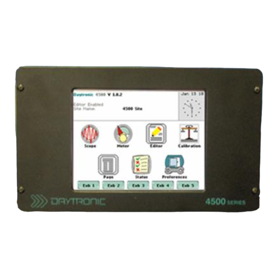
The steps below show how to set up and perform an operation check on the Model 4500. 1. Inspect the 4500 and note the 5D module location placement at the rear panel of the unit. Slot 1 is located at the far left moving towards the right to Slot 4. - Page 13 6. From the Home page, press Editor > Assign a 5D to a slot, to check if the 5D module installed matches the required physical placement of modules at the rear panel of the 4500, as noted in Step 1. If there is a conflict or to double-check 5D module placement, press the Get...
- Page 14 ID's button. The unit will query the installed modules and retrieve their appropriate serial number(s). The 4500 instrument organizes the 5D conditioner modules thru the serial number. To enable/display and enter the serial number, press the module slot icon box and follow the instructions displayed.
- Page 15 5D parameters that are appropriate for user application. Press Next and enter the parameters listed – Transducer Sensitivity, Expected Full Scale Input and Offset. These values are considered "absolute" calibration parameters which are 14 | Daytronic Model 4500 Quick Reference Guide...
- Page 16 13. To set up communications between the unit and an external computer, install the UtiliPAC410 software program bundled as a standard accessory with the purchase of Model 4500. To install, insert the UtiliPAC410 CD in the computer disc drive and double- click the SETUP program icon.
- Page 17 Once the software is configured, the program will initiate communications with the instrument and verify the Model and Type of the unit. Once communication between the 4500 and UtiliPAC410 is successfully established, the main menu appears. 14. Observe the instrument data by clicking on the Data Display tab. The channel data should match the readings on the Meter page of the 4500 instrument.
-
Page 18: Technical Specifications
Operating Temperature Range -10° C to 40° C (14° F to 104° F) Operating Relative Humidity 95%, noncondensing Transducer Types 4500 accommodates up to four (4) module types (Refer to the appropriate 5D manual for detailed information concerning the signal conditioners; The... - Page 19 Per 5D Module, selectable Internal 10 Point Programmable for the 5D input signal Linearization Onboard Memory 256 MB for setups and data Storage System Time Clock 1 Second resolution, recorder time 1ms resolution 18 | Daytronic Model 4500 Quick Reference Guide...
- Page 20 This page intentionally left blank. 19 | Daytronic Model 4500 Quick Reference Guide...
Need help?
Do you have a question about the 4500 and is the answer not in the manual?
Questions and answers