
Related Manuals for DayTronic 3770P


Summary of Contents for DayTronic 3770P
- Page 1 SB.1.1 MODEL 3770P DC STRAIN GAGE CONDITIONER INSTRUCTION MANUAL 3700 Instrument Series...
- Page 2 WARNING Death, serious injury, or fire hazard could result from improper connection of this instrument. Read and understand this manual before connecting this instrument. Follow all installation and operating instructions while using this instrument. Connection of this instrument must be performed in compliance with the National Electrical Code (ANSI/NFPA 70-2014) of USA and any additional safety requirements applicable to your installation.
-
Page 3: Safety Precautions
WARNUNG Der falsche Anschluß dieses Gerätes kann Tod, schwere Verletzungen oder Feuer verursachen. Bevor Sie dieses Instrument anschließen, müssen Sie die Anleitung lesen und verstanden haben. Bei der Verwendung dieses Instruments müssen alle Installation- und Betriebsanweisungen beachtet werden. Der Anschluß dieses Instruments muß in Übereinstimmung mit den nationalen Bestimmungen für Elektrizität (ANSI/NFPA 70- 2014) der Vereinigten Staaten, sowie allen weiteren, in Ihrem Fall anwendbaren Sicherheitsbestimmungen, vorgenommen werden. -
Page 4: Medidas De Seguridad
Medidas de seguridad Las medidas de seguridad siguientes deberán observarse cuando se realice cualquier tipo de conexión al instrumento. ο Cuando se haga conexiones a circuitos eléctricos o a equipo de activación por pulso, deberá abrirse sus respectivas cajas de seguridad. NO deberá hacerse ninguna conexión del instrumento en líneas eléctricas bajo tensión. ο... -
Page 5: Standard Accessories
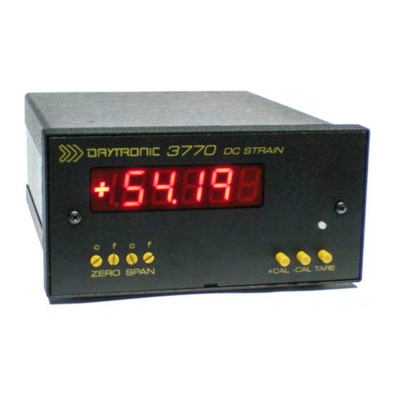
Sicherheitsvorkehrungen Die folgenden Sicherheitsvorkehrungen sind immer dann zu befolgen, wenn eine Verbindung zum Instrument hergestellt wird. ο Öffnen Sie beim Anschluß an elektrische Stromkreise oder Impulsauslösungseinrichtungen die entsprechenden Unterbrecher. Es dürfen KEINE Anschlüsse an das Instrument unter stromführenden Spannungsleitungen montiert werden. - Page 6 Model 3770 DC STRAIN GAGE PANEL METER 1.A.0.3770 3770 E N E R A L E S C R I P T I O N A N D P E C I F I C A T I O N S The Model 3770 is a single-channel panel instrument for traditional wheat-stone bridge type sensors;...
- Page 7 Model 3770 DC STRAIN GAGE PANEL METER 3770 SPECIFICATIONS Measurement Range: Adjustable; 0.5 to 10 mV/V; nominal full-scale. Dependent on Excitation level selected Transducer Types: Conventional 4-arm strain gage bridges, 120 to 10 k ohm Excitation: Selectable: 5.0 or 10.0 Vdc, with remote sense lines. Up to 70 mA. Power Supply: Voltage 90 - 250 VAC, 47 -63 Hz Consumption 10 Watts Physical Parameters: 5.
-
Page 8: Rear Panel Connections
Model 3770 DC STRAIN GAGE PANEL METER O N N E C T I O N S The Model 3770 I/O CONNECTIONS are via removable screw terminals which will accept wire sizes from AWG 12 to 26. NOTE: The recommended transducer cabling would be eight wire, twisted pair, individually shielded - wired as indicated (Fig. - Page 9 5 must be in the External position) NOTE: Daytronic Shunt Calibration circuit, when activated, will place the Shunt resistor across the + Sense Line (for positive shunt) or the – Sense Line (for negative shunt) with the connection of the Sensor’s Calibration Sense line located on the J2 connector - which is recommend to be connected to the + Signal line.
- Page 10 Model 3770 DC STRAIN GAGE PANEL METER O N N E C T I O N S J1 – Shunt Command Connections. Connection is used to activate the positive or negative Shunt calibration command from the rear panel. When the + or – R CAL terminal is connected to LOGIC COM via a switch or relay, the installed Shunt resistor will be connected across + Signal and + Sense or –...
- Page 11 Model 3770 DC STRAIN GAGE PANEL METER O N N E C T I O N S Fig. 6 - Transducer Cabling – DC Strain Gage- J2 + EXCITATION - EXCITATION + SENSE - SENSE + SIGNAL - SIGNAL CAL SENSE SHIELD Note: Sense lines must be connected at the transducer or at the instrument for proper operation.
- Page 12 Model 3770 DC STRAIN GAGE PANEL METER O N T R O L S Display Range and Decimal Point Selection Switch 1 - selects decimal point for position X.XXXXX Switch 2 - selects decimal point for position XX.XXXX Switch 3 - selects decimal point for position XXX.XXX Switch 4 - selects decimal point for position XXXX.XX Switch 5 - enables dummy zero display digit XXXXX Switch 6 &...
- Page 13 Model 3770 DC STRAIN GAGE PANEL METER O N T R O L S Analog Wide Gain and Zero Controls Two - 16 Position switches are used for wide control adjustment of the analog output signal from the 3770 meter; this in turn affects the digital readout for engineering unit’s adjustments as determined by the display settings.
- Page 14 Model 3770 DC STRAIN GAGE PANEL METER C o n t r o l s Analog Control Settings Front panel controls configure the Signal conditioner section for excitation level, mode of the analog output signal, low pass filter characteristics and shunt calibration being internal or external. 1 –...
- Page 15 Model 3770 DC STRAIN GAGE PANEL METER C o n t r o l s Analog Symmetry, + CAL, - CAL, TARE Symmetry - Adjust the negative gain slope for symmetrical analog adjustment and display reading with reference to the positive span value. 20 Turn potentiometer, with approx. ± 2% full scale authority +C A L Positive Calibration –...
- Page 16 Model 3770 DC STRAIN GAGE PANEL METER CALIBRATION This section contains the instructions for calibrating the 3770. Included is a functional description of the instrument front-panel (see Page 1). To perform calibration, proceed as follows. Connect Sensor and Analog terminals as required. Connect and apply power to the unit. The front- ( a ) panel digital display should light indicating the application of the AC input power.
- Page 17 Model 3770 DC STRAIN GAGE PANEL METER CALIBRATION – Shunt Calibration This section contains the instructions for calibrating the 3770 using the Shunt calibration method. Connect Power, Sensor and Analog terminals as required. Apply power. The front-panel digital ( a ) display should light indicating the application of the AC input power.
-
Page 18: Display Calibration
Model 3770 DC STRAIN GAGE PANEL METER CALIBRATION (cont.) – Shunt Calibration Equivalent Calculation If dead weight calibration is not practical and the transducer calibration data is unknown, the Equivalent Input value for the factory-installed calibration resistor can be approximated as follows, assuming that the mv/v sensitivity rating of the transducer and the bridge resistance is known. - Page 19 Model 3770 DC STRAIN GAGE PANEL METER Tech Tip on use of wide range settings for the DC Strain Gage Conditioner Due to multiple amplifier stages within the 3770 instrument, attention to the proper gain setting and understanding of the sensor inputs should be reviewed to produce a linear- amplified analog output signal and display reading. The wide span –...
-
Page 20: Fuse Replacement
Model 3770 DC STRAIN GAGE PANEL METER FUSE REPLACEMENT Should you suspect a blown fuse proceed as follows. WARNING Installation, operation and maintenance of this instrument must be performed by qualified personnel only. The National Electrical Code defines a qualified person as “one who has the skills and knowledge related to the construction and operation of the electrical equipment and installations, and who has received safety training on the hazards involved.”... - Page 21 Model 3770 DC STRAIN GAGE PANEL METER WARNING Do not replace fuse again if failure is repeated. Repeated failure indicates a defective condition that will not clear with replacement of the fuse. Refer condition to a qualified technician. ADVERTENCIA No reemplace el fusible nuevamente si se repite la falla. La repetición de las fallas indica una condición defectuosa que no se subsanará...
-
Page 22: Product Warranty And Repair
DC Strain gage Panel Meter Product Warranty and Repair rial Daytronic Corporation warrants its products to be free from defects in mate workmanship, under normal and proper use in accordance with our instructions, for the period of time specified below. Our liability under such... - Page 23 3700 SERIES “P” Option ANALOG PEAK CAPTURE INSTRUCTION MANUAL 3700 Instrument Series...
- Page 24 3700 “P” Option Instruction Manual, v. A.01 Issued 07/15 3700 SERIES “P” Option ANALOG PEAK CAPTURE INSTRUCTION MANUAL Daytronic Corporation Dayton, OH • Tel (800) 668-4745 www.daytronic.com...
-
Page 25: General Description
1. General Description The “P” option of the 3700 Series Meter is an added function card which provides the ability of the meter to capture and hold + Peak, -Peak, Max-Min or TIR value that originates from the base 3700 instrument. Any 3700 (except Horsepower 3741) can accomidate the "P"... -
Page 26: Dip Switch Configuration
DIP Switch Configuration Located on the rear panel above the main board connections, the 7 position dip switch configures the PEAK functions of the meter. The Default position of the switch is in the UP (ON) position as noted in the table below. -
Page 27: Pin Number
Functional Block Diagram of the PEAK switch settings 3. PEAK Interface I/O Connections Pin assignments for the 3700P board's 8-pin I/O connector (shown in Fig. 1) functional description Pin Number Function Output HAVE PEAK Output Logic Signal, indicates a Peak has been detected. Input TRACK or PEAK Input Logic Signal to Clear (Track) or to Arm for a Peak capture function... - Page 28 4. Setup conditions for the "P" option and TARE switch operation When the "P" option is installed - the front panel "TARE" Push/Push switch can be configured to operate in three seperate function modes for local operation depending on the DIP switch selection and/or logic inputs selected.
- Page 29 4. Interface I/O Connections Fig. 2 Interface Connector Operation Track/PEAK Via External Command (Switch, Open The 8 pin rear connector provides remote access to the Collector Transistor, or Peak operational parameters. All logic I/O are negative true TTL Logic) signals - logic common when active or true. Functional diagrams of the logic for enabling PEAK 2 (TRACK) functions are shown in Fig.
- Page 30 + PEAK Mode - captures and holds the most positive signal amplitude of the measurement within the positive quadrant of the signal. Switch 2 UP - Switch 3 UP Fig 3 - PEAK Mode - captures and holds the most negative signal amplitude of the measurement within the negative quadrant of the signal.
- Page 31 MAX + MIN Mode - captures and holds the most positive signal and the most negative signal amplitude in the positive and negative quadrants of the measurement resulting in an absolute analog output signal. Switch 2 UP - Switch 3 DOWN Fig 5 Note: When in Max-Min mode the analog signal may overrange due to the summing of the + Peak and - Peak captured signal.
- Page 32 Threshold Level Adjust and Have Peak Detection (Backout) Switch 6 - PEAK THRESHOLD DISPLAY ADJUST on the rear panel dip switch: When in the DOWN position, will switch the front panel display to provide level adjustment of the Threshold Potentiometer to provide a "No Peak Zone" around the Zero level. This adjustment is used to eliminate false Peak Captures around the zero measurement level as shown in the gray area of the Fig.
- Page 33 Quick Set-up operation 1. Determine the Peak Mode required Configure switch settings 2 and 3 for the proper function. 2. Select FAST or SELECT signal source Configure switch 1 - FAST will be the highest dynamic capture. SELECT will reflect the low pass filter selection on the main 3700 Analog Controls. 3.
- Page 34 Peak Capture Response The Peak Capture of the analog signal is performed using “capacitive” memory. This technique is very repeatable and does not involve digital sampling errors. It does, however result in a millivolt/second “leak rate” after the initial “capture” which varies depending on the Peak Capture cycle rate, amplitude of the analog signal and the wave shape of the signal being monitored.
- Page 35 Page left blank Page 11...
- Page 36 Daytronic Corporation. All specifications are subject to change without notice. Daytronic Corporation Dayton, OH • (800) 668-4745...
Need help?
Do you have a question about the 3770P and is the answer not in the manual?
Questions and answers