
Related Manuals for DayTronic 4030


Summary of Contents for DayTronic 4030
- Page 1 SB.5 MODEL 4030 SINGLE-CHANNEL AC LVDT INSTRUMENT INSTRUCTION MANUAL 4000 Instrument Series...
- Page 2 No part of this document may be reprinted, reproduced, or used in any form or by any electronic, mechanical, or other means, including photocopying and recording, or in any information storage and retrieval system, without permission in writing from Daytronic Corporation. All specifications are subject to change without notice.
- Page 3 Model 4030 Instruction Manual, v. SB.5 Pub. No. 4030M.5, Issued 10/96 Part No. 91472 MODEL 4030 SINGLE-CHANNEL AC LVDT INSTRUMENT INSTRUCTION MANUAL Daytronic Corporation Dayton, OH www.daytronic.com...
-
Page 5: Table Of Contents
Analog Output Connections ..........2.16 3. Operation: Use of Front-Panel Buttons ....... 3.1 Appendix A: Complete Standard Configuration ......A.1 Appendix B: 4030/Computer RS-232-C Connections ....B.1 Appendix C: Legend and Indicator Annunciation ...... C.1 Appendix D: Channel Linearization ........... D.1 Appendix E:... -
Page 6: Description And Specifications
Model 4030 Description and Specifications General 4030 Features Transducer Input(s) Real-Time Signal A to D Math Conditioning Conversion Processing + – x ÷ √ • Excitation • 16-bit (±32000 count) • • "y = mx + b" scaling • optional internal •... - Page 7 MAXIMUM, MINIMUM, and "MAX minus MIN" values for the "tared" analog input. Unless otherwise specified at the time of order, your Model 4030 has been set, prior to shipment, to a standard configuration . THIS...
- Page 8 Fig. 1. Different legend/indicator films may be optionally obtained. Via optional keyboard or computer, you can instruct the 4030 to light any one or a combination of given legends and indicators. See Appendix C for "Legend and Indicator Annunciation."...
- Page 9 Output Bandwidth: 40 Hz max. * Initial (uncalibrated) inaccuracy may be as great as ±3% of full scale. Maximum error that could occur upon replacement of a Model 4030 not followed by calibration is ±6% of full scale. Maximum allowable count tolerance is 0 ± 601 (for ZERO) and 20000 ± 601...
-
Page 10: Physical Layout
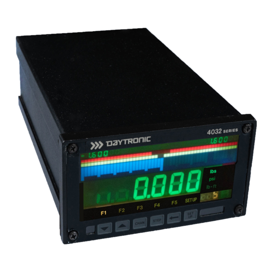
Physical Layout Study the following diagrams to acquaint yourself with your 4030's most important front and rear elements. Fig. 1 4030 Front Panel "Low-Low" Limit "High-High" Limit (LLL) (HHL) Bargraph Bargraph Low Endpoint "Low" Limit "High" Limit High Endpoint (LEP) - Page 11 Physical Layout Fig. 2(a) 4030 Rear Panel (AC Power) Analog Output AC Power Analog Input ON-OFF Connector Connector Connector Switch Fuse (see Fig. 10) (see Figs. 5, 6) Voltage Panel- Connector RS-232-C Logic I/O Selector Mount for Optional Interface Connector...
- Page 12 Physical Layout Fig. 2(b) 4030 Rear Panel (DC Power) Analog Output Analog Input ON-OFF Connector Connector Switch Fuse (see Fig. 10) (see Figs. 5, 6) Connector RS-232-C DC Power Logic I/O Panel- for Optional Interface Mount Connector Connector Keyboard Connector Clamp (see Fig.
-
Page 13: Panel Mounting
Panel Mounting You can easily mount a Model 4030 in your own precut panel. Cutout dimensions for a panel-mounted unit are standard DIN (see Fig. 3); panel thickness should not exceed 6 mm (0.24 in). When mounting a 4030, DO NOT REMOVE THE FRONT BEZEL. -
Page 14: Standard Channel Configuration
For rescaling and connection of the analog output, see Section 2.j. The 4030's Channel Nos. 4 and 14-16 are used as intermediate result registers or reference channels, and will not normally be displayed. The remaining scanned channels (Nos. 2, 3, 9-13,17, and 18) are not... -
Page 15: Standard Logic Configuration
V-DC and "Logic 0" as nominal +5 V-DC. The standard logic I/O configuration is shown in Fig. 4, below, with reference to the 10-terminal Logic I/O Connector on the rear of the 4030. For recommended logic interconnections, see Section 2.i. - Page 16 Standard Logic Configuration Bit No. Logic Function "BELOW BARGRAPH" VIOLATION OUTPUT Terminal 0 will be at a Logic 1 (0 V-DC) level whenever the reading of Channel 5 is less than the current "LEP" value for that channel. "LOW LOW" VIOLATION OUTPUT Terminal 1 will be at a Logic 1 (0 V-DC) level whenever the reading of Channel 5 is less than the current "LLL"...
-
Page 17: Using The Front-Panel Setup Buttons
The 4030 provides instant visual feedback for its front-panel buttons. Thus, pressing any button will light the green ON LINE indicator. This indicator is located in the lower right-hand corner of the 4030 front panel (see Fig. 1). It will remain lit as long as the button is pressed. - Page 18 (for each button's "RUN- TIME" function, see Section 3.) The small mnemonic display under the 4030's unit legends will alternately read "DIS" and the number of the channel that was on display when you pushed the SETUP button.
- Page 19 (Section 2.h) (HIGH HIGH LIMIT) (Section 2.h) (HIGH ENDPOINT) (Section 2.g) (ASSIGN SATELLITE NUMBER) (FILTER) (Section 2.f) (BAUD RATE) (DATA BITS) (STOP BITS) (PARITY) (LCD VIEWING ANGLE) (Section 2.c) (4000 SOFTWARE RELEASE DATE) * Applicable only to 4030 Channel 1. 1.14...
- Page 20 Using the Front-Panel Setup Buttons To move to the next parameter in sequence, STEP PRESS THE BUTTON As each parameter appears, you have the option of leaving it as it is and stepping to the next one by again pressing STEP, or of modifying its value by means of the "ARROW"...
- Page 21 Using the Front-Panel Setup Buttons In the negative realm , these buttons seem at first glance to function backwards. Thus, if the displayed parameter is preceded by a minus sign, then "increasing" the active digit by "1"—as a result of pressing the UP ARROW button—means decreasing that digit's absolute value by "1."...
- Page 22 Using the Front-Panel Setup Buttons NOTE: The above procedure will change the original values of one or more digits to the right of the most significant digit , except in the case where they are all originally zero. Therefore, you will most likely have to go back and reset these digits, using the LEFT ARROW and UP/DOWN ARROW buttons as explained in Step 5.
-
Page 23: Low Battery Warning
Data retention is guaranteed down to a battery level of 2.2 V-DC. Under normal usage, the battery should last about five years. The 4030 will check its battery every time the unit is turned on. If on powerup, the battery is found to be below 3.0 V-DC, the front-panel LCD will display a warning of "LO bat."... -
Page 24: Transducer Cabling
Transducer Cabling Located on the rear of the 4030, the 10-pin ANALOG INPUT CONNEC- TOR is shown in Fig. 5. Referring to the appropriate cabling diagram below, connect the wires of your TRANSDUCER CABLE to the corresponding screw terminals of the INPUT CONNECTOR. To... - Page 25 Transducer Cabling When wiring an LVDT transducer to the 4030, you should connect both series-opposed secondary coils to the terminal labelled "CENTER WIRE," as shown in Figs. 6(a) and 6(b). NOTE THAT THERE ARE SPECIAL +SIGNAL AND –SIGNAL CONNECTIONS FOR USE WITH LONG-STROKE LVDT'S (FULL- SCALE RANGE OF ±1 INCH OR GREATER).
- Page 26 SENS SENS –SENSE +SENSE SHIELD –EXCITATION Long-Stroke +SIGNAL LVDT's CENTER Sec. 1 WIRE Fig. 6(a) PRIMARY 4030 Transducer COIL SECONDARY Cabling: 5-Wire Sec. 2 COILS +EXCITATION LVDT Cabling (under 20 ft. in –SIGNAL length) LVDT INPUT HI – HI + –...
- Page 27 – CNTR – – SHLD WIRE SENS SENS –SIGNAL –SENSE +SENSE SHIELD +EXCITATION Fig. 6(c) 4030 Transducer +SIGNAL Cabling: 3-Wire Variable Reluctance Cabling (under 20 ft. –EXCITATION in length) LVDT INPUT HI – HI + – CNTR – – SHLD...
-
Page 28: Powerup
1. AC Operation This is "normal" operation for the Model 4030. A 4030 can operate from a line voltage of either 90-135 or 180-270 V-AC (47-63 Hz; 35 W maximum). The VOLTAGE SELECTOR SWITCH is located on the rear panel (see Fig. 2(a)). -
Page 29: Dc Operation
(isolators, regulators, uninterruptible power supplies, etc.). 2. DC Operation When ordered with the "V" ( Vehicle ) option, a 4030 may be operated from nominal 12 V-DC (30 W maximum). The actual tolerance range is 11-18 V-DC. - Page 30 CAUSE OF OVERLOAD BEFORE REACTIVATING THE INSTRUMENT. ----------IMPORTANT---------- In all cases, the "ground" terminal of the 4030 DC CONNEC- TOR should be connected either to the negative terminal of the vehicle battery or directly to the vehicle chassis. IT SHOULD NEVER BE LEFT UNCONNECTED. ALSO, TO MINIMIZE NOISE PICKUP, THE GROUND LEAD SHOULD BE AS SHORT AS POSSIBLE.
-
Page 31: Adjusting Lcd Viewing Angle
Adjusting LCD Viewing Angle You can easily optimize your 4030's LCD DIGITAL DISPLAY for your particular viewing angle . Following the procedure given in Section 1.f, above, press the instrument's front-panel SETUP key, and then "step" to the "LCD" parameter (the letters "LCd" should appear in the digital display, to indicate that the instrument is in "LCD adjustment"... -
Page 32: Selecting A Channel For Display
NOTE: As explained in Section 3, you can always use the LIVE DISPLAY button—when not in "SETUP MODE"—to call to display your 4030's Channel 5 ("tared" analog input). You can also use the MAX/MIN/MAX-MIN STEP button to cycle sequentially through... -
Page 33: Channel Calibration
Channel 1 ("LIVE" ANALOG INPUT). All other channels derive their readings from Channel 1. In general terms, you will normally calibrate your 4030's Channel 1 by commanding its microprocessor to compute and store two constant values: a ZERO OFFSET (based on setup entry "F0") and a SCALING FACTOR (based on entry "F1"). -
Page 34: Setting Channel Filters
Setting Channel Filters In addition to the normal-mode analog filtering applied to the Model 4030's "live" input channel (No. 1), digital filtering is also provided, with smoothing constants selectable via the front panel. The effect of the digital filter is to remove small unwanted dynamic signal components, while allowing large-scale fluctuations to pass unaffected. -
Page 35: Scaling The Bargraph Display
Channel 5 ("LIVE" INPUT WITH TARE), using the procedure given below. This same procedure may be used to scale the bargraph dis- play of any of the other 4030 data channels listed in Section 1.d. For the relation of BARGRAPH endpoint values to the other four limit-zone- defining parameters, see Fig. -
Page 36: Defining Limit Zones
Scaling the Bargraph Display NOTE, however, that the 4030's front panel furnishes a "truncated" numeric display of the two endpoint values of the currently displayed bargraph (see Fig. 1). That is, the endpoint numbers will appear with all but the first two significant digits converted to "0." THE RESULTING PRECISION OF THE DISPLAYED "LEP"... -
Page 37: Logic I/O Connections
Terminal 6 when it is in the current "ABOVE BARGRAPH" ZONE. Logic I/O Connections As shown in Fig. 4, the 4030's rear Logic I/O Connector has eight numbered LOGIC I/O terminals, plus a +5-V (LOGIC REFERENCE) terminal and a "GD" (GROUND) terminal. The "standard" 4030 configuration calls for logic OUTPUTS from Terminals 0 through 6. - Page 38 Logic I/O Connections For full LOGIC I/O SPECIFICATIONS, see the optional 4000 Series System Instruction Manual . Fig. 9 (a) Input from External TTL Logic Logic I/O Connector Fig. 9(b) Input from External Switch (0-7) Logic I/O Connector (0-7) Logic I/O Connector (0-7) OPEN = LOGIC 0 CLOSED = LOGIC 1...
-
Page 39: Analog Output Connections
Analog Output Connections Under the "standard" configuration, the 4030's Channel 19 is an analog output that corresponds to the "LIVE" INPUT WITH TARE (Channel 5) with a full range of ±10 V-DC and a maximum resolution of ±1 mV. This output is initially scaled for 1 mV of output per 0.001 unit of length for... -
Page 40: Operation: Use Of Front-Panel Buttons
Use of Front-Panel Buttons The "SETUP" functions of the 4030's six front panel buttons have been described in Section 1.f. These are the functions labelled on the buttons themselves. The "RUN-TIME" button functions are as follows: BUTTON No. 1 ("LIVE DISPLAY"): Each Push : Calls Channel 5 ("LIVE"... - Page 41 App. A Complete Standard Configuration For a full explanation of the parameters listed in this section, see the optional 4000 Series System Instruction Manual . CHANNEL CONFIGURATION Channel 1.000 1.000 1.000 0.000 1.000 0.000 1.000 0.000 1.000 0.000 5.000 5.000 5.000 5.000 5.000...
- Page 42 App. A Complete Standard Configuration CHANNEL LIMIT LOGIC Channel 1 - 4 6 - 13 17 - 19 CALCULATION CHANNELS Channel 1(CHN4)+0 1(CHN1-CHN4)+0.000 1.000(MAX CHN5)+0.000 1.000(MIN CHN5)+0.000 1.000(CHN6–CHN7)+0.000 1(CHN14)+0 1(CHN14)+0 1(CHN14)+0 ANALOG OUTPUT Channel 1000(CHN5)+0 EXECUTES Number EXU/ 0 - 12 ANN3=1 ANN3=0:ANN4=1 ANN4=0:ANN5=1...
- Page 43 App. A Complete Standard Configuration BUTTON EXECUTES Button Number EXB and EXB/ CHN14=0:ANN1TO5=0:ANN1=1:DIS=5 CHN4=CHN1 INC14:SDI CHN6TO7=CHN5 ANNUNCIATION Annunciator Number 2 - 6 LOGIC I/O Number 0 - 7 LOGIC SOURCES Number 0 - 6 LIM,NON 7 - 10 EXT,NON LIM,NON EXT,NON 13 - 15 LIM,NON...
- Page 44 OTHER GENERAL SETUP PARAMETERS SCN = 1,19 TER = 19 EXC = 5 SBC = 1 ASN = 0 LGO = 4030 STANDARD EDT = Y DIS = 5 BAR = DIS BEP = LEP FLA = 1000 CPC = 9...
-
Page 45: Appendix B: 4030/Computer Rs-232-C Connections
App. B 4030/Computer RS-232-C Connections If you did not order a specific RS-232-C Interface Cable with your 4030, you will have to provide your own connection. Fig. 11 shows suggested cabling between a 4030 and a computer, terminal, buffered printer, etc., that uses a 25-Pin RS-232-C Connector . - Page 46 COMMON COMMON FULL HANDSHAKE 25-Pin RS-232-C (RECOMMENDED) Connector** Required for connection of the 4000 instrument to an IBM or IBM- compatible computer, but not to a Daytronic Model PC-HSICA. Male connector required for Model PC-HSICA. 11(b) COMPUTER 4000 Instrument RECEIVE...
- Page 47 App. B 4030/Computer RS-232-C Connections 11(c) 4000 COMPUTER Instrument RECEIVE TRANSMIT TRANSMIT RECEIVE COMMON COMMON NO HANDSHAKE 25-Pin RS-232-C Connector Fig. 12 Suggested RS-232-C Interface Connections (to 9-Pin RS-232-C Connector) COMPUTER 4000 Instrument RECEIVE RECEIVE TRANSMIT TRANSMIT COMMON COMMON 9-Pin RS-232-C...
-
Page 48: Appendix C: Legend And Indicator Annunciation
ANN n = 0 [CR] inches milli/in SETUP Fig. 13 Front-Panel 2 3 4 5 "Annunciators" * The SETUP indicator cannot be affected by the ANNUNCIATOR (ANN) command. It will only be on when the 4030 is in "SETUP" mode. -
Page 49: Appendix D: Channel Linearization
App. D Channel Linearization When your 4030's "live" input channel (No. 1) is derived from a nonlinear transducer, you may calibrate it by means of one of the instrument's eight internal "look-up" tables. The purpose of such a table is to linearize the signal in question, to "bend" its characteristic curves to achieve at least approximately "straight-line"... - Page 50 App. D Channel Linearization LNS = 7 Measured Output Fig. 14 Typical Linearization Curve, with Seven Segments Using the "ARROW" buttons, enter for "F0" the exact minimum load value established in Step 5, expressed in appropriate engineering units. Press the STEP button again to display Channel 1's "F1" para- meter (this is the value of the endpoint of the first linearization segment).
- Page 51 , you should enter all LINEARIZATION POINTS expressed to the nearest hundredth of an inch (e.g., "1.00"). The 4030's display of any channel based on Channel 1 will then reflect this precision. 11. Continue to enter as many LINEARIZATION POINTS as you specified in the original LNS entry (Step 3, above).
-
Page 52: Appendix E: Changing The Battery
App. E Changing the Battery If, on powerup, your 4030 displays the "LO bat" warning, you should take the following steps to replace the battery (READ ALL OF THESE DIRECTIONS COMPLETELY BEFORE YOU BEGIN): If possible, offload your 4030's present configuration data to disk... - Page 53 8. Align the dual-board assembly with the guide slots on the inside of the 4030 case and reinsert the assembly all the way (if it is wrong- side-up, you won't be able to insert it). 9. Replace the four rear-panel corner screws. As you screw down the rear panel, the internal board connectors will automatically engage with the front display assembly.
- Page 54 Daytronic Corporation Dayton, OH • (800) 668-4745 www.daytronic.com...
Need help?
Do you have a question about the 4030 and is the answer not in the manual?
Questions and answers