Table of Contents
Advertisement
Quick Links
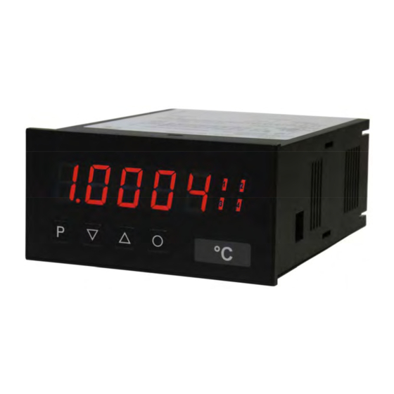
User manual M3
Alternating voltage/Alternating current signal rms-value (TRMS)
0-50 VAC, 0-10 VAC, 0-1 AAC, 0-5 AAC
Technical features:
• red display of -19999...99999 digits (optional: green, orange or blue display)
• minimal installation depth: 120 mm without plug-in terminal
• min-/max memory
• 30 parameter driven setpoints
• optical threshold value indication at threshold value exceedance / undercut
• zero-key for triggering of HOLD, TARA
• permanent min-/max-value recording
• volume measurement (totaliser)
• arithmetic function
• zero point slowdown
• programming interlock via access code
• protection class IP65 at the front
• plug-in terminal
• option: digital input
• option: 1 or 2 analog outputs
• option: 2 or 4 relay outputs or 8 PhotoMos outputs
• option: interface RS232 or RS485
M3_14GB.pdf Stand: 15.10.2011
96x48
Advertisement
Table of Contents

Related Manuals for DayTronic M3


Summary of Contents for DayTronic M3
- Page 1 User manual M3 Alternating voltage/Alternating current signal rms-value (TRMS) 0-50 VAC, 0-10 VAC, 0-1 AAC, 0-5 AAC Technical features: • red display of -19999…99999 digits (optional: green, orange or blue display) • minimal installation depth: 120 mm without plug-in terminal •...
- Page 2 Identification STANDARD TYPES ORDER NUMBER Alternating current, voltage M3-1VR5B.0004.470AD Housing size: 96x48 mm M3-1VR5B.0004.570AD M3-1VR5B.0004.670AD Options – breakdown of order code: M 3- 1 V R 5 B. 0 0 0 4. 5 7 2 A D Standard type M-line...
-
Page 3: Table Of Contents
Contents Assembly Electrical connection Function and operation description Setting up the device 4.1. Switching on 4.2. Standard parameterisation (flat operation level) 4.3. Extended parameterisation (professional operation level) 4.3.1. Signal input parameters „INP“ 4.3.2. General device parameters „FCT“ 4.3.3. Safety parameters „COD“ 4.3.4. -
Page 4: Assembly
1. Assembly 1. Assembly Please read the Safety advices on page 52 before installation and keep this user manual for future reference. Gap for physical unit After removing the fixing elements, insert the device. Check the seal to make sure it fits securely. Click the fixing elements back into place and tighten the clamping screws by hand. -
Page 5: Electrical Connection
2. Electrical connection 2. Electrical connection... -
Page 6: Function And Operation Description
3. Function and operation description 3. Function and operation description Operation The operation is divided into three different levels. Menu level (delivery status) This level is for the standard settings of the device. Only menu items which are sufficent to set the device into operation are displayed. - Page 7 3. Function and operation description Function chart:...
-
Page 8: Setting Up The Device
4. Setting up the device 4. Setting up the device 4.1. Switching on Once the installation is complete, you can start the device by applying the voltage supply. Before, check once again that all electrical connections are correct. Starting sequence For 1 second during the switching-on process, the segment test (8 8 8 8 8) is displayed followed by an indication of the software type and, after that, also for 1 second the software version. - Page 9 4. Setting up the device Menu level Parameterisation level Setting the decimal point, The decimal point on the display can be moved with [▲] [▼] and confirmed with [P]. The display then switches back to the menu level again. Setting up the display time, then The display time is set with [▲] [▼].
- Page 10 4. Setting up the device Menu level Parameterisation level HY-1: Hysteresis for limit values, The delayed reaction of the alarm is the difference to the threshold value, which is defined by the hysteresis. Function for threshold value undercut /exceedance, Fu-1: A limit value undercut is selected with Louu (for LOW = lower limit value), a limit value exceedance with High (for HIGH = higher limit value).
- Page 11 4. Setting up the device Menu level Parameterisation level Activation / deactivation of the programming lock or completion of the standard parameterisation with change into menu group level (complete function range), run: With the navigation keys [▲] [▼], you can choose between the deactivated key lock Uloc (works setting) and the activated key lock Loc, or the change into the menu group level ProF.
-
Page 12: Extended Parameterisation (Professional Operation Level)
4. Setting up the device 4.3. Extended parameterisation (Professional operation level) 4.3.1. Signal input parameters Menu group level Menu level Menu level Parameterisation level Selection of the input signal, tYPE: Available as measuring input options are 0-50/-10 VAC or 0-5/-1 AAC signals as works calibration (without application of the sensor signal) and Se.50v, Se.10v, se.5a and se.1a as sensor calibration (with the sensor applied). - Page 13 4. Setting up the device Menu level Parameterisation level Setting the decimal point, The decimal point on the display can be moved with [▲] [▼] and confirmed with [P]. The display then switches back to the menu level again. Setting up the display time, then The display time is set with [▲] [▼].
- Page 14 4. Setting up the device Menu level Parameterisation level SPCt: Number of additional setpoints, 30 additional setpoints can be defined to the initial- and final value, so linear sensor values are not linearised. Only activated setpoint parameters are displayed. dIS.01 … dIS.30: Display values for setpoints, Under this parameter setpoints are defined according to their value.
-
Page 15: General Device Parameters „Fct
4. Setting up the device 4.3.2. General device parameters Menu group level Menu level Menu level Parameterisation level Display time, DISEC: then The display is set up with [▲] [▼]. Thereby it jumps until 1 second in increments of 0.1 seconds and until 10.0 seconds in increments of 1.0. - Page 16 4. Setting up the device Menu level Parameterisation level Zero point slowdown, ZErO: At the zero point slowdown, a value range around the zero point can be preset, so the display shows a zero. If e.g. a 10 is set, the display would show a zero in the value range from -10 to +10;...
- Page 17 4. Setting up the device Menu level Parameterisation level Assignment (deposit) of key functions, tASt : Via totAL the current value of the totaliser can be displayed for approx.7 seconds, after this the device changes back on the parameterised display value. If tot.rE is deposited, the totaliser can be set back by pressing of the navigation keys [▲] [▼], the device acknowledges this with ooooo in the display.
- Page 18 4. Setting up the device Menu level Parameterisation level Special function digital input, dIG.In: … In operation mode, the above shown parameter can be laid on the optional digital input, too. Function description see tASt.4. Back to menu group level, rEt: With [P] the selection is confirmed and the device changes into menu group level „–...
-
Page 19: Safety Parameters „Cod
4. Setting up the device 4.3.3. Safety parameters Menu group level Menu level Menu level Parameterisation level User code U.Code: Via this code reduced sets of parameters can be set free. A change of the U.CodE can be done via the correct input of the A.CodE (master code). Master code, A.Code: By entering A.CodE the device will be unlocked and all parameters are released. -
Page 20: Serial Parameters „Ser
4. Setting up the device Menu level Parameterisation level AL.LEU: Release/lock alarm parameters, This parameter describes the user relase/user lock of the alarm. - LIMIt, here only the range of value of the threshold values 1-4 can be changed. - ALrM.L, here the range of value and the alarm trigger can be changed. - ALL, all alarm parameters are released. -
Page 21: Analog Output Parameters 1 „Out
4. Setting up the device Menu level Parameterisation level Timeout, tIout: The monitoring of the data transfer is parameterised in seconds up to max. 100 seconds; there is no monitoring with an input of 000. The timeout is adjusted from the smallest to the largest digit with the navigation keys [▲] [▼] and confirmed digit per digit with [P]. - Page 22 4. Setting up the device Menu level Parameterisation level Setting the final value of the analog output, Out.En: The final value is adjusted from the smallest to the highest digit with [▲] [▼] and confirmed digit per digit with [P]. A minus sign can only be parameterised on the highest digit.
-
Page 23: Analog Output Parameters 2 „Out2
4. Setting up the device 4.3.6. Analog output parameters for analog output 2 Menu group level Menu level Menu level Parameterisation level Selection reference of analog output, Ou2Pt: The analog output signal can refer to different functions, in detail these are the current measurand, the min-value, the max-value or the totaliser-/sum function. - Page 24 4. Setting up the device Menu level Parameterisation level Overflow behaviour, Ou2.fl: To recognise and evaluate faulty signals, e.g. by a controller, the overflow behaviour of the analog output can be defined. As overflow can be seen either EdGE, that means the analog output runs on the set limits e.g.
-
Page 25: Relay Functions „Rel
4. Setting up the device 4.3.7. Relay functions Menu group level Menu level Menu level Parameterisation level Alarm relay 1, rEL-1: The same applies for relays 2-4 …. …. Each setpoint (optional) can be linked up via 4 alarms (by default). This can either be inserted at activated alarms Al-1/4 or de-activated alarms Aln1/4. - Page 26 4. Setting up the device Menu level Parameterisation level Alarms for relay 1, CoM-1: …. The allocation of the alarms to relay 1 happens via this parameter, one alarm or a group of alarms can be chosen. With [P] the selection is confirmed and the device changes into menu level.
-
Page 27: Alarm Parameters „Al1
4. Setting up the device Menu level Parameterisation level Alarms for relay 5, CoM-5: …. The allocation of the alarms to relay 5 happens via this parameter, one alarm or a group of alarms can be chosen. With [P] the selection is confirmed and the device changes into menu level. - Page 28 4. Setting up the device Menu level Parameterisation level Threshold values / Limit values, LI-1: The limit value defines the threshold, that activates/deactivates an alarm. Hysteresis for Threshold values, HY-1: The delayed reaction of the alarm is the difference to the threshold value, which is defined by the hysteresis.
-
Page 29: Totaliser (Volume Metering) „Tot
4. Setting up the device 4.3.9. Totaliser (Volume metering) Menu group level Menu level Menu level Parameterisation level Totaliser state, total: The totaliser makes measurements on a time base of e.g. l/h possible, at this the scaled input signal is integrated by a time and steadily (select Stead) or temporarily (select temp) safed. -
Page 30: Programming Interlock, Run
4. Setting up the device Menu level Parameterisation level Totaliser reset, tot.re The reset value is adjusted from the smallest to the highest digit with the navigation keys [▲] [▼] and digit per digit confirmed with [P]. After the last digit, the display switches back to the menu level. -
Page 31: Alarms / Relay
4. Setting up the device 4.4. Alarms / Relays This device has 4 virtual alarms that can monitor one limit value in regard of an undercut or exceedance. Each alarm can be allocated to an optional relay output S1-S2; furthermore alarms can be controlled by events like e.g. -
Page 32: Interface Rs232 / Rs485
4. Setting up the device 4.5. Interfaces RS232 and RS485 The interface RS485 is connected via a screened data line with twisted wires (Twisted-Pair). On each end of the bus segment a termination of the bus lines needs to be connected. -
Page 33: Factory Settings
5. Factory settings 5. Factory settings 5.1. Default values Standard parameterisation (flat operation level) Parameter Menu items Default values Type of input 0…50 VAC 0…10 VAC 0…5 AAC 0…1 AAC Sensor Sensor calibration 50 calibration 50 Sensor Sensor Sensor calibration calibration calibration 1 AAC... - Page 34 5. Factory settings Menu items Parameter Default values Limit value 2 Hysteresis 2 Operation type Undercut Exceedance Exceedance User code Master code Standard Parameter Professional Standard operation interlock operation operation Extended parameterisation (professional operation level) Signal input parameters Parameter Menu items Default values Type of input 0…50 VAC...
- Page 35 5. Factory settings Menu items Parameter Default values Display of decimal point Measuring 0.1 second 10.0 seconds 1.0 second time Analog final value Analog final value Display offset Display unit °C °F Number of setpoints Display value Analog value … Display value Analog value Display...
- Page 36 5. Factory settings Menu items Parameter Default values Display overflow General device parameters Parameter Menu items Default values Display time 0,1 second 10 seconds 1 second Round a value no rounding Increments of Increments of Increments of no rounding Arithmetics Reciprocal Square root Square...
- Page 37 5. Factory settings Parameter Menu items Default values Function up- Extremum Alarm limit Alarm limit Tara function /down-function (min/max) Totaliser value Totaliser reset Extremum Set tara value Display reset measurand Special Tara function Set tara value Totaliser value Totaliser function reset 4th key Alarm 1...
- Page 38 5. Factory settings Safety parameters Parameter Menu items Default values User code Administrator code Analog output Range of Range of All parameters level changeable value value&source parameters Alarm level Limit value Range of All parameters changeable value&source parameters Serial parameters Parameter Menu items Default values...
- Page 39 5. Factory settings Analog output parameters 1 Parameter Menu items Default values Source Current Minimum Maximum Totaliser Hold Current measurand measurand Sliding average value Output range 0...10 mA 0...20 mA 4...20 mA 4...20 mA Final value Initial value Overflow Run to limit Switch to final Switch to start Switch to...
- Page 40 5. Factory settings Analog output parameters 2 Parameter Menu items Default values Source Current Minimum Maximum Totaliser Hold Current measurand measurand Sliding average value Output range 0...10 mA 0...20 mA 4...20 mA 4...20 mA Final value Initial value Overflow Run to limit Switch to final Switch to start Switch to...
- Page 41 5. Factory settings Relay functions Parameter Menu items Default values Relay at Alarm 1 at Alarm 4 at Alarm 1 function1 not Alarm 1 not Alarm 4 via logic declined activated Logic relay 1 active if at active if no active if all active if at active if at...
- Page 42 5. Factory settings Menu items Parameter Default values Relay function at Alarm 1 at Alarm 4 at Alarm 3 not Alarm 1 not Alarm 4 via logic declined activated Logic relay 3 active if at active if no active if all active if at active if at least 1 alarm...
- Page 43 5. Factory settings Menu items Parameter Default values Relay function at Alarm 1 at Alarm 4 at Alarm 5 not Alarm 1 not Alarm 4 via logic declined activated Logic relay 5 active if at active if no active if all active if at active if at least 1 alarm...
- Page 44 5. Factory settings Menu items Parameter Default values Relay function at Alarm 1 at Alarm 4 at Alarm 5 not Alarm 1 not Alarm 4 via logic declined activated Logic relay 7 active if at active if no active if all active if at active if at least 1 alarm...
- Page 45 5. Factory settings Alarm parameters Menu items Parameter Default values Alarm source Current Minimum Maximum Totaliser Hold Current measurand measurand measurand measurand Sliding external input average value (DigIn/Tast4) Limit value 1 Hysteresis 1 Function 1 Undercut Exceedance Exceedance Activation 100 seconds delay 1 Deactivation 100 seconds...
- Page 46 5. Factory settings Parameter Menu items Default values Alarm source Current Minimum Maximum Totaliser Hold Current measurand measurand measurand measurand Sliding external input average value (DigIn/Tast4) Limit value 2 Hysteresis 2 Function 2 Undercut Exceedance Exceedance Activation 100 seconds delay 2 Deactivation 100 seconds delay...
- Page 47 5. Factory settings Menu items Parameter Default values Function 3 Undercut Exceedance Exceedance Activation 100 seconds delay 3 Deactivation 100 seconds delay Parameter Menu items Default values Alarm source Current Minimum Maximum Totaliser Hold Current measurand measurand measurand measurand Sliding external input average value (DigIn/Tast4)
- Page 48 5. Factory settings Alarm parameters Menu items Parameter Default values Alarm source Current Minimum Maximum Totaliser Hold Current measurand measurand measurand measurand Sliding external input average value (DigIn/Tast4) Limit value 5 Hysteresis 5 Function 5 Undercut Exceedance Exceedance Activation 100 seconds delay 5 Deactivation 100 seconds...
- Page 49 5. Factory settings Parameter Menu items Default values Alarm source Current Minimum Maximum Totaliser Hold Current measurand measurand measurand measurand Sliding external input average value (DigIn/Tast4) Limit value 6 Hysteresis 6 Function 6 Undercut Exceedance Exceedance Activation 100 seconds delay 6 Deactivation 100 seconds delay 6...
- Page 50 5. Factory settings Parameter Menu items Default values Function 7 Undercut Exceedance Exceedance Activation 100 seconds delay 7 Deactivation 100 seconds delay 7 Parameter Menu items Default values Alarm source Current Minimum Maximum Totaliser Hold Current measurand measurand measurand measurand Sliding external input average value...
-
Page 51: Reset To Default Values
5. Factory settings Totaliser (Volume metering) Parameter Menu items Default values Totaliser state permanent quick saving saving Time base seconds minutes hours seconds Divisor 10^0=1 10^6 10^0=1 Places after decimal point Totaliser reset 5.2. Reset to default values To return the unit to a defined basic state, a reset can be carried out to the default values. The following procedure should be used: •... -
Page 52: Technical Data
6. Technical data 6. Technical data Housing Dimensions 96x48x120 mm (BxHxD) 96x48x139 mm (BxHxD) including plug-in terminal +0.8 +0.6 Panel cut-out 92.0 x 45.0 Wall thickness up to 15 mm Fixing screw elements Material PC polycarbonate, black, UL94V-0 Sealing material EPDM, 65 Shore, black Protection class standard IP65 (front side), IP00 (back side) - Page 53 6. Technical data Output Analog output 0/4-20 mA or 0-10 VDC 16 Bit switchable Switching outputs Relay with change-over contacts 250 VAC / 5 AAC; 30 VDC / 5 ADC Switching cycles 30 x 10 at 5 AAC, 5 ADC ohm resistive burden 10 x 10 mechanically Diversification according to DIN EN 50178 /...
-
Page 54: Safety Advices
Please inform the supplier immediately of any damage. Installation The M3-device must be installed by a suitably qualified specialist (e.g. with a qualification in industrial electronics). Notes on installation •... -
Page 55: Error Elimination
8. Error elimination 8. Error elimination Error description Measures The unit permanently indicates • The input has a very high measurement, check overflow. the measuring circuit. • With a selected input with a low voltage signal, it is only connected on one side or the input is open. •... - Page 56 M3_14GB.pdf Stand: 15.10.2011...
Need help?
Do you have a question about the M3 and is the answer not in the manual?
Questions and answers