Table of Contents
Advertisement
Advertisement
Table of Contents

Related Manuals for DayTronic 3500 Series


Summary of Contents for DayTronic 3500 Series
- Page 1 SB.3 3500 INSTRUMENT SERIES INSTRUCTION MANUAL...
- Page 2 No part of this document may be reprinted, reproduced, or used in any form or by any electronic, mechanical, or other means, including photocopying and recording, or in any information storage and retrieval system, without permission in writing from Daytronic Corporation. All specifications are subject to change without notice.
- Page 3 3500 Series Instruction Manual, v. SB.3 Pub. No. 3500M.3, Issued 1/97 Part No. 91668 3500 INSTRUMENT SERIES INSTRUCTION MANUAL Daytronic Corporation 2211 Arbor Blvd. • Dayton, OH 45439-1521 • Tel (937) 293-2566 • Fax (937) 293-2586 www.daytronic.com...
-
Page 4: Table Of Contents
ONTENTS NTRODUCTION a. Using This Manual ......................1.1 b. General Instrument Descriptions 1. Introduction ........................1.1 2. The Model 3510 Thermocouple Conditioner ............1.2 3. The Model 3530 LVDT Conditioner ................1.2 4. The Model 3540 Frequency Input Conditioner ............ 1.2 5. - Page 5 ONTENTS 6. Filter: FILTER Key ......................3.12 7. Analog Output: ANO Key ..................3.13 8. Limits: LIMIT Key ......................3.14 9. Tare Offset: TARE Key ....................3.17 10. Print and Output Parameters: PRINT Key ............3.18 b. Configuring Through the RS-232/485 Interface ........
- Page 6 ONTENTS PERATION a. RS-232/485 Communications 1. RS-232/485 Outputs: CHN and DMP Commands ..........5.1 2. Data-Transmission Format ..................5.1 3. “Opening” a Node to Receive Commands from the Computer ....5.2 b. Peak Capture ........................5.3 c. Tare and Reset ........................
- Page 7 Connector) ........................2.12 14(a) Connections for a Network of Three Instrument Nodes (where the first is a 3500 Series Instrument) ............2.13 14(b) RS-485 Cabling Between the Model 5E485 and the FIRST Network Node (if it is a 3500 Series Instrument) ..............2.14 14(c) RS-485 Cabling Between Successive 3500 or 4000 Instrument Nodes ..
- Page 8 ONTENTS 17(a) Logic I/O Connections: Input from External Switch .......... 2.17 17(b) Logic I/O Connections: External TTL Logic ............2.17 17(c) Logic I/O Connections: External Controller ............2.17 17(d) Logic I/O Connections: Output to External Relay ..........2.18 Limit Zones ........................3.15 High and Low Hysteresis Windows ................
-
Page 9: Introduction
ESCRIPTIONS 1.b.1 I NTRODUCTION Every 3500 Series instrument can be completely set up and operated either through the front-panel keypad or via simple mnemonic commands received from an external computer or terminal through its RS-232/485 Interface Port. The instrument can transmit data from this port in response to an interrogation from an external computer, or can send it to an RS-232 serial printer when the PRINT button is pressed (assuming that it is set to RS-232 mode). - Page 10 NTRODUCTION • logic-input control of peak capture, unlatching of latched limit conditions, application of tare offset, and initiation of hard-copy printout For complete specifications, see Appendix A. 1.b.2 T 3510 T ODEL HERMOCOUPLE ONDITIONER This instrument accepts a temperature signal from a Type B, E, J, K, R, S, or T Thermocouple.
- Page 11 NTRODUCTION 1.b.5 T 3560 V ODEL OLTAGE ONDITIONER This is a general-purpose instrument for conditioning, displaying, and monitoring the signal received from a DC-to-DC LVDT, potentiometer-type sensor, or other external two-wire voltage source, either floating (differential) or grounded (sin- gle-ended). The input signal may also represent output from some other instru- ment system.
-
Page 12: Physical Layout
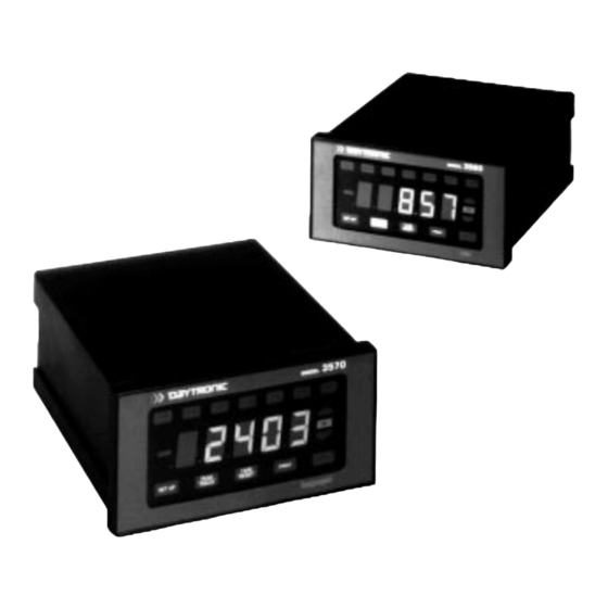
NTRODUCTION HYSICAL AYOUT Study the following diagrams to acquaint yourself with the most important front and rear elements. Fig. 1(a) shows a typical "RUN-TIME" display, with "live" data and limit-status annunciation. Note the four front-panel buttons that are active (but not necessari- ly lit) during normal run-time operation. - Page 13 NTRODUCTION NOTE: Your instrument is supplied with a large assortment of standard engineer- ing unit legends on a 4" x 5 1/2" dry transfer sheet. The selected legend may be rubbed directly onto the instrument's front-panel frame using the tip of a ball-point pen or the blunt end of a stylus or other burnishing tool.
-
Page 14: Panel Mounting
NTRODUCTION Fig. 2(b) Rear Panel for All Analog Output Other 3500 Series Models Programming Pins* (behind cover plate—see Fig. 15) Analog Input Analog Output Logic I/O Connector** Connector Connector (see Fig. 7, 8, 9, or 10) (see Fig. 16) (see Figs. 5, 17) -
Page 15: Summary Of Setup Button Functions
NTRODUCTION UMMARY OF ETUP UTTON UNCTIONS The use of the SETUP buttons is explained in detail in Sections 3.a and 4.a. The following table summarizes the relevant functions: Button Button Function (in SETUP MODE): Used to exit current setup procedure ("COM," "RANGE," "CAL," SET UP etc.) or to exit SETUP MODE. -
Page 16: Summary Of Logic I/O Functions
NTRODUCTION Press top segment to increment digit (up to "9") Fig. 4 Use of NUMERIC BUTTONS in SETUP MODE FILTER LIMIT Press "–" TARE SET UP PRINT ENTER RESET segment to change polarity Press bottom segment to decrement digit (down to "0") I/O F UMMARY OF OGIC... -
Page 17: Mnemonic Commands
– CALIBRATE NEMONIC OMMANDS There are two ways to issue commands to a 3500 Series instrument. One way is through the front-panel push buttons. These buttons allow you • to enter all necessary SETUP COMMANDS, as explained in Sections 3.a and 4.a*;... - Page 18 NTRODUCTION English mnemonics, and includes SETUP ("WRITE"), INTERROGATION ("READ"), and TRANSMISSION-INITIATING commands. In RS-485 (MULTINODE) operation, every command received at the RS-232/485 Interface Port will evoke a response from that port (either "ACKNOWLEDGED," "NOT ACKNOWLEDGED," or the re- quested PARAMETER or DATA VALUE(S)). For a complete listing of mnemonic commands and responses, see Appendix B.
-
Page 19: Setup : Connections And Power
NALOG NPUT ONNECTOR All 3500 Series instruments except the Model 3510 Thermocouple Conditioner and the Model 3578 AC Strain Gage Conditioner use the "standard" Analog Input Connector. Shown in Fig. 2(b), this connector is located on the rear of the unit. -
Page 20: Model 3510 Transducer Cabling
ETUP ONNECTIONS AND OWERUP Open TC Detection Programming Jumpers Fig. 6 Model 3510 Transducer Cabling Thermocouple This terminal NOT USED Conditioner Analog Input Board – SIGNAL – This terminal NOT USED + SIGNAL Strain Relief Post Ground SHIELD The Model 3510 is normally preset at the factory for positive off-scale "open TC" indication. - Page 21 ETUP ONNECTIONS AND OWERUP d. When wiring a variable reluctance transducer to the 3530, you must install a 10-kilohm "half-bridge completion" resistor between the –SIGNAL line and each of the two EXCITATION lines, as shown in Figs. 7(c) and 7(d). LVDT INPUT HI –...
- Page 22 ETUP ONNECTIONS AND OWERUP LVDT INPUT HI – HI + – CNTR – – SHLD WIRE SENS SENS –SIGNAL SHIELD +SENSE Fig. 7(d) Model 3530 +EXCITATION Transducer Cabling: 5-Wire Variable Reluctance Cabling (20 ft. or longer) +SIGNAL –EXCITATION –SENSE 2.a.4 C ONNECTING A REQUENCY 3540...
- Page 23 ETUP ONNECTIONS AND OWERUP EXCITATION SIGNAL INPUTS EXCITATION SIGNAL INPUTS – – – – SHLD SHLD SIGA SIGA SHIELD SHIELD +SIGNAL +SIGNAL FREQUENCY FREQUENCY SOURCE SOURCE – – –SIGNAL –SIGNAL Fig. 8(a) Model 3540 Transducer Fig. 8(b) Model 3540 Transducer Cabling: Differential (Floating) Cabling: Single-Ended (Grounded) Frequency Input...
- Page 24 ETUP ONNECTIONS AND OWERUP 2.a.5 C ONNECTING A OLTAGE 3560 OURCE TO THE ODEL Fig. 9(a) gives standard cabling for connecting to the Model 3560 Voltage Con- ditioner a general ANALOG SIGNAL SOURCE, floating or grounded, with its own power supply (if required); Fig. 9(b), for connecting an EXTERNAL ZERO-TO-FULL- SCALE POTENTIOMETER with a resistance from 2 to 10 kilohms, using the instru- ment's ±12-V excitation;...
- Page 25 ETUP ONNECTIONS AND OWERUP 2.a.6 C DC S ONNECTING A TRAIN 3570 RANSDUCER TO THE ODEL Four-wire strain gage cabling (Fig. 10(a)) is to be used with the Model 3570 DC Strain Gage Conditioner when the cable is under 20 feet in length. In this case, the +SENSE and –SENSE lines are tied to the corresponding EXCITATION lines, and also the CALIBRATION SENSE line to the +SIGNAL line, at the CONDITIONER CONNECTOR.
- Page 26 ETUP ONNECTIONS AND OWERUP 2.a.7 C AC S ONNECTING AN TRAIN 3578 RANSDUCER TO THE ODEL As shown in Fig. 2(a), the Model 3578 AC Strain Gage Conditioner's Analog Input Board mates with a special CONDITIONER CONNECTOR. This connector allows direct solder-terminal attachment of cable leads. The connector's internal solder terminals are labelled 1 through 10 and A through L.
-
Page 27: Calibration Resistor
ETUP ONNECTIONS AND OWERUP CONDITIONER CONNECTOR –SENSE +SENSE +SIGNAL External Fig. 11(c) Model 3578 SHUNT CALIBRATION Transducer Cabling: RESISTOR (User- Installation of User’s Supplied) External Shunt Calibration Resistor SHIELD CONDITIONER CONNECTOR +SENSE +EXCITATION –SIGNAL +SIGNAL Fig. 11(d) Model 3578 Transducer Cabling: 8-Wire Cabling to LEBOW 1600 SERIES –EXCITATION TRANSDUCER (ONLY) - Page 28 Section 3.a.3 how to set the node number and other necessary RS-232 communications parameters via the front-panel buttons. If you did not order a specific RS-232-C Interface Cable with your 3500 Series instrument, you will have to provide your own connection. Fig. 12 shows suggest- ed cabling between the instrument and a computer, terminal, printer, etc., that...
-
Page 29: Single-Node") Connections
ETUP ONNECTIONS AND OWERUP RS-232/485 Interface Connector—Male (see Fig. 2) Fig. 12 Suggested RS-232-C Interface Connections Pin No. Function (to 25-Pin RS-232-C Connector) DATA (RS-485) RECEIVE (RS-232) TRANSMIT (RS-232) DATA TERMINAL READY (RS-232) COMMON DATA (RS-485) +12 V (RS-485) CLEAR TO SEND (RS-232) SHIELD Computer 3500... -
Page 30: Multinode Network") Connections
ULTINODE ETWORK ONNECTIONS You can also set a 3500 Series instrument's RS-232/485 Interface Port for RS-485 intercommunications with a multidrop network of up to 99 independent Daytronic signal conditioning instruments (3500 Series, 4000 Series with “N” Option, and/or 5000 Series)—all controlled by a supervisory computer with RS-232-C I/O. To do so, YOU MUST ASSIGN THE 3500 INSTRUMENT A UNIQUE NONZERO NODE NUMBER. - Page 31 RS-485 Terminator (for chains over 500 ft.) Fig. 14(a) Connections for a Network of Three Instru- ment Nodes (where the first is a 3500 Series instrument) For RS-485 communications, the relevant pins of the RS-232/485 Interface Port are as follows: Pin No.
- Page 32 100- Shielded Twisted Pairs or other cable intended for EIA RS-422/485 Fig. 14(b) RS-485 Cabling Between the Model 5E485 and the FIRST Network Node (if it is a 3500 Series instrument) RS-232/485 Interface Port RS-232/485 Interface Port (3500 or 4000 Series Instrument)
-
Page 33: Analog Output Connections
ETUP ONNECTIONS AND OWERUP NALOG UTPUT ONNECTIONS As indicated in Fig. 15, the ±5-V analog output signal of the Model 3530 LVDT Conditioner, Model 3560 Voltage Conditioner, Model 3570 DC Strain Gage Conditioner, or Model 3578 AC Strain Gage Conditioner may represent the state of the conditioned input (A) after the FIXED ANALOG FILTER;... -
Page 34: Logic Input/Output Connections
ETUP ONNECTIONS AND OWERUP Fig. 16 shows how an external device connects to the ANALOG OUTPUT CON- NECTOR on the rear of the conditioner, including the Models 3510 and 3540. The output is single-ended, and returns to "SIGNAL COMMON" (i.e., GROUND). For offsetting and scaling of the ANALOG OUTPUT, see Section 3.a.7. -
Page 35: Powerup
ETUP ONNECTIONS AND OWERUP Logic I/O Connector Fig. 17(a) Logic I/O Connections: Input from External Switch OPEN = LOGIC 0 +5 V CLOSED = LOGIC 1 Logic Input* Also includes "+" and "–" Calibration Inputs for the Model 3570 DC Strain Gage Conditioner (ONLY)—see Fig. - Page 36 ETUP ONNECTIONS AND OWERUP Logic I/O Connector Fig. 17(d) Logic I/O Connections: Output to External Relay +5 V Logic Output Coil Resistance > 500 OWERUP Accepting a line voltage from 90 to 265 V-AC (50-400 Hz; 10 W max), your 3500 Series instrument will automatically sense the power input level and adjust its internal regulator accordingly.
- Page 37 ETUP ONNECTIONS AND OWERUP • The entire LCD (buttons and digital display) will be turned momentarily ON and OFF. • The number "88888" will be displayed. • The display will show either EPASS or EFAIL, following a checksum per- formed on the EEPROM where program parameters are stored. If EFAIL appears, it means that there is a difference between the calculated checksum and the stored checksum.
- Page 38 This page intentionally blank. 2.20...
-
Page 39: Setup : Instrument Configuration
SETUP MODE NTERING AND XITING Your 3500 Series instrument's "setup configuration" can be fully established via the front-panel push buttons—including the NUMERIC BUTTONS described in Section 1.e. For configuration setup by means of MNEMONIC COMMANDS issued to the instrument through its RS-232/485 Interface, see Section 3.b, below. -
Page 40: Security Code
ETUP NSTRUMENT ONFIGURATION IN ORDER TO REGISTER THE CHANGE. IF YOU ONLY PRESS SETUP AFTER CHANGING A SETUP VALUE, YOU WILL RETURN TO THE "SETUP" DISPLAY WITHOUT HAVING ACTUALLY "ENTERED" THE CHANGE. ALSO PLEASE NOTE: IF YOU ATTEMPT TO ENTER AN OUT-OF-RANGE OR OTH- ERWISE UNACCEPTABLE VALUE FOR A GIVEN SETUP PARAMETER, THE UNIT WILL DISPLAY AN ERROR NUMBER, SUCH AS If this occurs, refer to the ERROR-CODE TABLE in Appendix C. - Page 41 ETUP NSTRUMENT ONFIGURATION If a nonzero SECURITY CODE is already in effect, the operator will be asked to enter it whenever the SETUP key is pressed: The procedure for entering the existing code is as follows: d. Press ENTER A zero will be displayed. e.
- Page 42 ETUP NSTRUMENT ONFIGURATION d. When the desired baud rate appears, press ENTER to return to the "BAUD" display. Then press COM. The unit will display "DATA" (for "NUMBER OF DATA BITS"): e. To display the current data-bits setting, press ENTER. If you don't want to dis- play the number of data bits, press COM again and proceed to Step h.
- Page 43 ETUP NSTRUMENT ONFIGURATION n. To display the current node-number setting, press ENTER. If you don't want to display the node number, press COM again and proceed to Step q. IMPORTANT: FOR RS-232-C COMMUNICATIONS, THE NODE NUMBER MUST REMAIN AT THE INITIAL SETTING OF ZERO ("00"). For configuration of RS-485 (MULTINODE NETWORK) communications, see Section 3.a.4, below.
- Page 44 ETUP NSTRUMENT ONFIGURATION u. Press either COM or ENTER to display the word "TER" (for "TERMINATOR"). The OUTPUT TERMINATOR—also called "END-OF-TRANSMISSION TERMINA- TOR (EOT)"—is a string of up to four ASCII CONTROL CHARACTERS from [00] through [1F] to be transmitted at the end of each complete transmission from the RS-232/485 Interface Port (in either RS-232 or RS-485 mode)—including every response to a received MNEMONIC COMMAND (see Appendix B).
-
Page 45: Communications Parameters: Com Key
ETUP NSTRUMENT ONFIGURATION 3.a.4 RS-485 C : COM K OMMUNICATIONS ARAMETERS You can use the front-panel buttons to set up RS-485 communications for every instrument "NODE" within a MULTINODE NETWORK, exactly as explained in Sec- tion 3.a.3, above, for RS-232 linkage to a single device. NOTE, HOWEVER, THE FOLLOWING IMPORTANT POINTS: a. -
Page 46: Input Range: Range Key
ETUP NSTRUMENT ONFIGURATION 3.a.5 I : RANGE K NPUT ANGE Once you are in SETUP MODE, press the button labelled RANGE The unit will display the word "RANGE": —unless it is a Model 3510 Thermocouple Conditioner, in which case it will dis- play the word "TYPE": NOW REFER TO THE SECTION BELOW THAT APPLIES TO YOUR SPECIFIC CON- DITIONER MODEL. - Page 47 ETUP NSTRUMENT ONFIGURATION 6. When the desired temperature scale appears, press ENTER. The conditioner will now tell you whether its internal reference-junction compensation is cur- rently enabled. If it is, you may now disable it, if you intend to provide your own Controlled Ambient Temperature Zone for reference-junction purposes.
-
Page 48: Setting The Model 3540'S Frequency Input Range And Sensitivity
ETUP NSTRUMENT ONFIGURATION 3.a.5.c S 3540’ ETTING THE ODEL REQUENCY NPUT ANGE AND ENSITIVITY The Model 3540 Frequency Conditioner must be set to match the full-scale input range of the frequency source. 1. If, after pressing the RANGE button, you want to display the current input- range setting, press ENTER. - Page 49 ETUP NSTRUMENT ONFIGURATION 3. When the desired voltage range appears, press ENTER to return to the "RANGE" display. Then press SETUP to return to the "Setup" display, and pro- ceed to Section 3.a.6. 3.a.5.e S 3570’ DC S ETTING THE ODEL TRAIN NPUT...
-
Page 50: Filter: Filter Key
ETUP NSTRUMENT ONFIGURATION 3.a.6 F : FILTER K ILTER For the Model 3530 LVDT Conditioner, Model 3560 Voltage Conditioner, Model 3570 DC Strain Gage Conditioner, and Model 3578 AC Strain Gage Conditioner, you can select a low-pass corner frequency of 5, 10, or 20 Hz for the instrument's analog filter. -
Page 51: Analog Output: Ano Key
ETUP NSTRUMENT ONFIGURATION If you don't want to display the current DIGITAL FILTER setting, press FILTER to return to the "FILTER" display. To display the digital filter setting, press ENTER. A number from 0 through 9 will be displayed. These "filter constants" signify increasing amounts of automatic digital filtering, where "0"... -
Page 52: Limits: Limit Key
ETUP NSTRUMENT ONFIGURATION e. To display the current analog-output gain value, press ENTER. If you don't want to display the gain, press SETUP to return to the "Setup" display. To change the amplification value, use the NUMERIC BUTTONS as explained in Section 1.e to modify the displayed number (again, you cannot change its "0.1"... - Page 53 ETUP NSTRUMENT ONFIGURATION Greater Than Zone Between ("OK") Zone Less Than Zone Fig. 18 Limit Zones As explained below, when you define each limit value, you will indicate whether you want the limit to be LATCHING or NONLATCHING. You will also be able to specify a HYSTERESIS "WINDOW"...
- Page 54 ETUP NSTRUMENT ONFIGURATION Greater Than Zone HI Hysteresis Window OK Zone "Live" Data Reading LO Hysteresis Window Less Than Zone Fig. 19 High and Low Hysteresis Windows The reason for setting up a HIGH HYSTERESIS WINDOW is to prevent low- level signal noise from toggling control outputs on and off when the data reading is in the neighborhood of the HIGH LIMIT value.
-
Page 55: Tare Offset: Tare Key
ETUP NSTRUMENT ONFIGURATION at the rear LOGIC I/O CONNECTOR or by a RELEASE (RLS) command received through the RS-232/485 Interface (see Appendices B and F). To change the HIGH LATCH status, you can toggle between ON and OFF by pressing the top or bottom segment of any display character. When the desired HIGH LATCH status appears, press ENTER to return to the "HILAT"... - Page 56 ETUP NSTRUMENT ONFIGURATION c. To change the current TARE REGISTER value, use the NUMERIC BUTTONS as explained in Section 1.e to modify the displayed number. d. When the desired TARE REGISTER value appears, press ENTER to return to the "TARE" display. Then press SETUP to return to the "Setup" display. 3.a.10 P : PRINT K RINT AND...
- Page 57 ETUP NSTRUMENT ONFIGURATION ber is "0" (as it usually is in the single-node case). For the precise response format, see Section 5.a.2. If the "ECHO" status is OFF, it means that the node- number "echo" will not appear in any CHN transmission. To change the "ECHO"...
-
Page 58: Configuring Through The Rs-232/485 Interface
NTERFACE When proper RS-232/485 communications have been established with an exter- nal computer or terminal, it is possible for a 3500 Series instrument to receive and respond to SETUP COMMANDS issued directly to it through this interface. There is a specific SETUP COMMAND for each of the front-panel button proce- dures described in the previous section, with the exception of the node-number assignment (see the NODE (NOD) command, below). -
Page 59: Thermocouple Type (Model 3510 Only)
ETUP NSTRUMENT ONFIGURATION COMMAND TERMINATOR (CMT): CMT=c [CMT] Sets the COMMAND (or "INPUT") TERMINATOR to "c" (where c is a single ASCII character entered as a hexadecimal byte in square brackets, [01] through [1F]). END-OF-TRANSMISSION TERMINATOR (EOT): EOT=$ [CMT] Sets the END-OF-TRANSMISSION (or "OUTPUT") TERMINATOR to "$" (where $ is a string of up to four ASCII characters, each entered as a hexadecimal byte in square brackets, [01] through [1F]). -
Page 60: Excitation (Models 3570 And 3578 Only)
ETUP NSTRUMENT ONFIGURATION Conditioner "r" Actual Input Model value Range or Scale 3560 Voltage Conditioner 0.5V ±0.5 V-DC ±1.0 V-DC ±2.0 V-DC ±5.0 V-DC ±10.0 V-DC ±20.0 V-DC 3570 DC Strain Gage Conditioner 0.75 mV/V 1.5 mV/V 3.0 mV/V 3578 AC Strain Gage Conditioner 0.75 mV/V 1.50 mV/V 3.00 mV/V... -
Page 61: Analog Output
ETUP NSTRUMENT ONFIGURATION 3.b.8 A NALOG UTPUT ANALOG OUTPUT OFFSET (AOO): AOO=v [CMT] Sets the analog output offset to "v" (where v is a percentage of full scale to the nearest tenth of a percent between -25.5% and 25.5%). ANALOG OUTPUT GAIN (AOG): AOG=v [CMT] Sets the analog output gain to "v"... - Page 62 ETUP NSTRUMENT ONFIGURATION ECHO (ECO): ECO=ON [CMT] or ECO=OFF [CMT] Sets the node-number "ECHO" to "ON" or "OFF." LIMITS (LIM): LIM=ON [CMT] or LIM=OFF [CMT] Sets the "LIMIT-STATUS INDICATION" to "ON" or "OFF." (See also the LABEL (LBL) and ENGINEERING UNIT STRING (EUS) commands described in Section 5.a.2.) 3.b C RS-232/485 I...
-
Page 63: Setup : Instrument Calibration
ETUP NSTRUMENT ALIBRATION NTRODUCTION ALIBRATION ECHNIQUES The calibration methods that apply to each 3500 Series conditioner model are summarized in the following table. Calibration Techniques Conditioner Model 3510 TC Conditioner 3530 LVDT Conditioner 3540 Frequency Conditioner 3560 Voltage Conditioner 3570 DC Strain... -
Page 64: Actual" Two-Point (Deadweight) Calibration
EADWEIGHT ALIBRATION This conventional "zero and span" procedure can be applied to all 3500 Series conditioner models. It should be used when the transducer signal is relatively lin- ear and when there are at least two independently and accurately known calibra- tion values. -
Page 65: Calculated Calibration
ETUP NSTRUMENT ALIBRATION 4.a.4 I 15-S NTERNAL EGMENT INEARIZATION For an input signal derived from a nonlinear transducer, an internal "look-up" table can be created.* This table will be automatically reloaded on every powerup. The purpose of such a table is to linearize the signal in question, to "bend" its charac- teristic curves to achieve at least approximately "straight-line"... -
Page 66: Phase And Symmetry Adjustment Of The Model 3578 Ac Strain Gage Conditioner
ETUP NSTRUMENT ALIBRATION HASE AND YMMETRY DJUSTMENT OF THE 3578 AC S ODEL TRAIN ONDITIONER PLEASE NOTE: THIS PROCEDURE APPLIES ONLY TO THE MODEL 3578 AC STRAIN GAGE CONDITIONER. FOR ALL OTHER CONDITIONERS, YOU MAY IGNORE THIS MANUAL SECTION. Before you calibrate your Model 3578 for the first time, you should perform the follow- ing PHASE AND SYMMETRY ADJUSTMENT procedure. - Page 67 ETUP NSTRUMENT ALIBRATION Press ENTER once again. This will return you temporarily to a display of the "live" analog input. Press ANY KEY EXCEPT CAL OR SETUP. This will freeze the displayed data value. Using the NUMERIC BUTTONS as explained in Section 1.e, change the displayed value to "0"...
- Page 68 ETUP NSTRUMENT ALIBRATION HASE YMMETRY DJUSTMENT FOR A 1800 S EBOW ERIES RANSDUCER WHEN USING THE MODEL 3578 WITH A LEBOW 1800 SERIES TRANSDUCER, YOU SHOULD FIRST INSTALL THE SHUNT RESISTOR SUPPLIED WITH THE TRANSDUCER. Refer to Fig. 11(c) and connect the resistor between Pin 5 of the CONDITIONER CONNECTOR and the transducer's +SIGNAL line (you will not use the "CAL SENSE"...
- Page 69 28. Now press CAL. The unit will again display "FORCE." 29. To exit the CAL button sequence and return to the "Setup" display, press SETUP. THE LEBOW 1800 / DAYTRONIC 3578 SYSTEM IS NOW FULLY CALIBRATED. YOU NEED NOT PERFORM A SUBSEQUENT "DEADWEIGHT" OR "SIMULATED" CALIBRA- TION.
- Page 70 ETUP NSTRUMENT ALIBRATION ALIBRATING HROUGH THE RONT ANEL 4.c.1 U CAL K SING THE When you are in SETUP MODE and press the button, the unit will display the name of the calibration technique that is currently in effect. Thus, if your 3500 instrument was last set up for "TWO-POINT" calibra- tion—either "actual"...
- Page 71 ETUP NSTRUMENT ALIBRATION b. Once again, press ENTER This will return you temporarily to a display of the "live" analog input. c. Apply an accurately known value of input loading to the source transducer—a value less than 50% of the nominal full-scale range. If it is possible to set this "zero point"...
-
Page 72: Calibrating Through The Front Panel
ETUP NSTRUMENT ALIBRATION Press the CAL button again. This will return you temporarily to a display of the "live" analog input. h. Apply a second accurately known value of input loading—a value from 80% to 100% of the transducer's nominal full-scale rating. Now press ANY KEY EXCEPT CAL OR SETUP. - Page 73 ETUP NSTRUMENT ALIBRATION EQUIVALENT INPUT can be approximated from a knowledge of the Shunt Cali- bration Resistance (R); the transducer's Bridge Resistance (B); and the transduc- er's Full-Scale Sensitivity (K, in mV/V, full scale). To determine the EQUIVALENT INPUT (X) as an approximate percentage of full- scale output, you may use the following equation: 25000(mV/V)B a.
-
Page 74: Input
ETUP NSTRUMENT ALIBRATION 4.c.4 15-S EGMENT INEARIZATION NOTE: THIS CALIBRATION TECHNIQUE DOES NOT APPLY TO THE THERMO- COUPLE CONDITIONER. 4.c.4.a I NTRODUCTION Whether you set up your internal linearization by directly entering input/output values or by "forcing" each output value based on a corresponding value of actual input loading, you should first divide your transducer's rated operating range into a number of approximately equal segments (up to a total of fifteen). -
Page 75: By "Table
ETUP NSTRUMENT ALIBRATION been changed since the reset can be recovered through the RS-232/485 Inter- face (see the LIN command, Section 4.d). You should reset the linearization table when you are linearizing your 3500 instru- ment for the first time, or whenever you want to relinearize it by the "FORCE" pro- cedure described in Section 4.c.4(c), below. - Page 76 ETUP NSTRUMENT ALIBRATION Pressing the CAL button at this point will take you immediately to the highest segment in the existing table, which is one more than the last defined seg- ment, unless the last defined segment is Segment No. 15. If, for example, the table already contains five fully defined line segments, pressing CAL will dis- play "SEG 6,"...
-
Page 77: By "Force
ETUP NSTRUMENT ALIBRATION NUMERIC BUTTONS to change it, if desired. Press ENTER to return to the "SEG 0" display. Now you can add more points, if desired, or quit. 12. After you have defined the last segment of your curve, press SETUP to return to the "Setup"... -
Page 78: Calculated" Calibration
ETUP NSTRUMENT ALIBRATION button to set the DECIMAL-POINT LOCATION of the displayed number. SINCE THE PRECISION OF THE MEASUREMENTS REPORTED BY THE 3500 INSTRU- MENT WILL ALWAYS MATCH THAT OF THE LINEARIZATION POINTS, IT IS IMPORTANT THAT ALL "FORCE" ENTRIES BE EXPRESSED TO THE SAME PRECISION (DECIMAL-POINT LOCATION). -
Page 79: For The Model 3570 (Only)
ETUP NSTRUMENT ALIBRATION instrument simply by loading a SCALING FACTOR equal to the full-scale range to which the instrument has been set, expressed in the desired engineering units and to the desired measurement precision. 1. Once you have selected "CALCULATED" calibration as explained in Section 4.c.1, the unit will display "CALC": 2. - Page 80 HROUGH THE NTERFACE When proper RS-232/485 communications have been established with an exter- nal computer or terminal, SETUP commands can be issued to a 3500 Series instrument for remotely controlled "TWO-POINT (DEADWEIGHT)" calibration (either "actual" or "simulated"), 15-SEGMENT LINEARIZATION, and "CALCULAT- ED"...
-
Page 81: Calibrating Through The Rs-232/485 Interface
ETUP NSTRUMENT ALIBRATION 4.d.2 “T ” C OINT ALIBRATION ZERO (ZRO): ZRO=z [CMT] Sets the ZERO OFFSET ("b" term) that is to be used whenever "MXB" calibra- tion is in effect such that the existing input yields a reading of "z" (full range is ±32700). - Page 82 ETUP NSTRUMENT ALIBRATION placed in "LIN" calibration mode. Note too that these linearization commands do not apply to the Model 3510 Thermocouple Conditioner. LINEARIZER RESET (LNR): LNR [CMT] An "IMPERATIVE" command that resets the internal linearization table. For the effects of resetting the table, see Section 4.c.4(a), above. NOTE: Applying this command will automatically set the active calibration mode to "MXB"...
- Page 83 ETUP NSTRUMENT ALIBRATION SCALING FACTOR (EMM): EMM=m [CMT] Sets to "m" the SCALING FACTOR ("m" coefficient) that is to be used whenev- er "MXB" calibration is in effect (full range is ±32700). Also sets desired preci- sion (decimal-point location). Note: The following command applies to the Model 3540 FREQUENCY CONDI- TIONER only.
- Page 84 This page intentionally blank. 4.22...
- Page 85 UTPUTS DMP C OMMANDS A 3500 Series instrument will issue output from its RS-232/485 Interface Port in response to • a command to "PRINT" from the front-panel PRINT button or the rear logic I/O connector (when the interface is in RS-232 mode);...
-
Page 86: Run -Time Operation
PERATION c. An optional LIMIT-STATUS INDICATION number of "-1," "0," or "1," if so indicat- ed by the user during the PRINT button setup procedure (Section 3.a.10) or by application of a LIMITS (LIM) command of LIM=ON [CMT] d. An optional "TAILER" string defined by an ENGINEERING UNIT STRING (EUS) command of EUS=$ [CMT] where "$"... -
Page 87: Peak Capture
PERATION APTURE During setup, a 3500 Series instrument can be placed in either PEAK CAPTURE or TRACK/HOLD mode, as follows: 1. Enter SETUP MODE by pressing the SETUP button and entering the current security code, if necessary (as explained in Section 3.a.1). - Page 88 PERATION +PEAK READING ANALOG INPUT TRACK + PEAK Fig. 22 Capture and Hold of Successively Higher-Valued Maxima ANALOG +PEAK READING INPUT + PEAK + PEAK Fig. 23 Capture and Hold of Successively Lower-Valued Maxima Using Peak Reset Fig. 23 shows the capture of successively lower-valued signal maxima. Here, it is necessary to reset the "+PEAK"...
-
Page 89: Tare And Reset
PERATION ARE AND ESET You can control a 3500 instrument's tare function in any one of three ways: 1. By the front-panel TARE/RESET button (WHEN THE "TARE" TERMINAL OF THE REAR LOGIC I/O CONNECTOR IS AT "LOGIC 0"). Pressing this button once will place the unit in "TARE"... -
Page 90: Initiating Hard-Copy Printouts
PERATION NITIATING RINTOUTS There are two ways you can cause your 3500 instrument to output formatted data from its RS-232/485 Interface Port according to the time interval specified by the operator (Section 3.a.10), WHEN THAT PORT IS SET TO RS-232 MODE*: 1. -
Page 91: Track/Hold Function
RACK UNCTION See Section 5.b, above, for instructions on setting a 3500 Series instrument to TRACK/HOLD mode. When a 3500 instrument is in TRACK/HOLD mode, it can be commanded to freeze the analog input signal in any of three ways: 1. - Page 92 This page intentionally blank.
- Page 93 3500 Series Specifications ENERAL PECIFICATIONS (These specifications apply equally to all 3500 Series models.) Physical: DIN package outline of extruded metal, with splash-resistant front panel; secure rear connections via screw terminals. Instrument weight approx- imately 3.25 lb (1.47 kg). For dimensions, see Fig. 25, below.
-
Page 94: Eries Specifications
3500 S ERIES PECIFICATIONS and RS-485. RS-485 configuration allows operation as an individual data-col- lection "node" within a computer-controlled network. NOTE: RS-485 conver- sion is required at the computer's I/O port. Logic Inputs and Outputs: TTL- and CMOS-compatible; isolated (±1500 V) from power and communication ports. -
Page 95: Individual Conditioner Specifications
3500 S ERIES PECIFICATIONS Common-Mode Rejection Ratio: -116 dB at DC; -120 dB at 60 Hz Input Impedance: Differential: 10 megohms; Common-Mode: 0.5 megohm Offset: Initial: ±0.005 mV; vs. Temperature: ±0.0001 mV/°C; vs. Time: ±0.001 mV/month Gain Accuracy: ±0.05% of absolute mV input range of -10 to +80 mV Gain Stability: Vs. - Page 96 3500 S ERIES PECIFICATIONS Analog Peak Capture: Positive analog peak with minimum full-scale input pulse duration of 15 msec (to 1% of full-scale accuracy), 25 msec (to 0.1% of full-scale accuracy), and 35 msec (to 0.02% of full-scale accuracy); digitally held for indefi- nite display;...
- Page 97 3500 S ERIES PECIFICATIONS Corner Frequency Response at . . . 2.5 Hz 5 Hz 10 Hz - 3 dB 2.5 Hz 5 Hz 10 Hz -60 dB 15 Hz 32 Hz 65 Hz Step Response Settling Time (Full-Scale Output) 2.5 Hz 5 Hz 10 Hz...
-
Page 98: Model 3570 Dc Strain Gage Conditioner
3500 S ERIES PECIFICATIONS Frequency Characteristics and Step-Response Settling Times: AFTER THE FIXED ANALOG FILTER or AFTER +PEAK IN "TRACK" MODE: 3 dB down at 2 KHz; 60 dB down at 16 kHz. Settling Time to 1% of final value: 0.6 msec;... - Page 99 3500 S ERIES PECIFICATIONS Analog Output: Range scalable in 0.1% increments between 74.5% and 125.5% of nominal input.* May be sourced by conditioned input (A) after the FIXED ANA- LOG FILTER; (B) after PEAK CAPTURE; or (C) after the SELECTABLE ANALOG FIL- TER (see Fig.
- Page 100 3500 S ERIES PECIFICATIONS Gain Accuracy*: ±0.025% of full scale,typical, following calibration Gain Stability: Vs. Temperature: ±50 ppm/°C; vs. Time: ±20 ppm/month Analog Filtering for Displayed Reading: 5-pole filter with selectable low-pass corner frequency of 5, 10, or 20 Hz Corner Frequency Response at .
-
Page 101: Appendix B Command And Response Syntax
OMMAND AND ESPONSE YNTAX Appendix B Command and Response Syntax : RS-232 RS-485 M NTRODUCTION ODES WHEN A 3500 INSTRUMENT'S INTERFACE PORT IS SET TO RS-232 MODE, every valid INTERROGATION command received at that port will elicit an appropriate RESPONSE, as will the special transmission-initiating commands CHANNEL (CHN) and DUMP (DMP), described in Section 5.a. -
Page 102: Setup Commands
OMMAND AND ESPONSE YNTAX ETUP OMMANDS A SETUP (or "WRITE") COMMAND instructs the 3500 instrument to give a particular value to a particular setup parameter. It will have the general form [MNEMONIC] = [value] [CMT] Examples of setup commands are EMM=3000 [CMT], FIL=5 [CMT], ECO=OFF [CMT], and SAV=ON [CMT]. - Page 103 OMMANDS NOTE: Unless otherwise indicated, every command in the following list applies equally to all 3500 Series conditioner models. For the use of CONFIGURATION SETUP commands, see also Section 3.b. For the use of CALIBRATION SETUP commands, see also Section 4.d. For the use of RUN-TIME commands, see also Section 5.
- Page 104 OMMAND AND ESPONSE YNTAX CALIBRATION CAL=MXB [CMT] Sets the active calibration method to "MXB" (i.e., "TWO-POINT" or "CALCULATED" cali- bration using the "y = mx+b" linear equation). For RS-485 (only), returns ACK [EOT]. CAL=LIN [CMT] Sets the active calibration method to "15-SEGMENT LINEARIZATION." Not recognized by the Model 3510 Thermocouple Conditioner.
- Page 105 OMMAND AND ESPONSE YNTAX END-OF-TRANSMISSION TERMINATOR EOT=$ [CMT] Specifies an OUTPUT (or "END-OF-TRANSMISSION") TERMINATOR of $, where $ is a string of up to four ASCII characters, each entered as a hexadecimal byte in square brackets ([01] through [1F]—the current transmission will be instantly halted if the instrument perceives an EOT character of [00]).
- Page 106 OMMAND AND ESPONSE YNTAX measured phenomenon, expressed in the desired engineering units and precision). For RS-485 (only), returns ACK [EOT]. IMPORTANT: THIS COMMAND SHOULD ONLY BE APPLIED WHEN THE 3540 IS SET FOR "TWO-POINT" OR "CALCULATED" CALIBRATION—THAT IS, WHEN THE CAL=MXB [CMT] COMMAND IS IN EFFECT.
- Page 107 OMMAND AND ESPONSE YNTAX LHY [CMT] Reads current LOW HYSTERESIS window depth. Returns p [EOT]. LIMITS LIM=ON [CMT] Includes LIMIT-STATUS Indicator Number in all transmissions from the RS-232/485 Interface Port in response to a CHANNEL (CHN) or DUMP (DMP) command. For RS-485 (only), returns ACK [EOT].
- Page 108 OMMAND AND ESPONSE YNTAX MVV MV/V CALIBRATION — Model 3570 DC Strain Gage Conditioner only MVV=i,u [CMT] Sets an appropriate SCALING FACTOR for the Model 3570 DC Strain Gage Condition- er based on "i" (the transducer sensitivity rating in mV/V, full scale) and "u" (the nomi- nal full-scale rating of the transducer expressed in the desired engineering units and precision), if excitation = 10 V;...
- Page 109 OMMAND AND ESPONSE YNTAX PRN [CMT] Reads current PRINT ENABLE status. Returns ON [EOT] or OFF [EOT]. RESPONSE RES=f [CMT] Sets the selectable analog filter corner to f Hz, where f = 5, 10, or 20 for the Model 3530 LVDT Conditioner, Model 3560 Voltage Conditioner, Model 3570 DC Strain Gage Conditioner, and Model 3578 AC Strain Gage Conditioner.
- Page 110 OMMAND AND ESPONSE YNTAX SHUNT CALIBRATE—NEGATIVE — Model 3570 DC Strain Gage Conditioner and Model 3578 AC Strain Gage Conditioner only SHN=ON [CMT] Closes the DC or AC Strain Gage Conditioner's shunt-calibration switch for a negative up-scale reading. Opens the positive shunt-calibration switch if it is currently closed. For RS-485 (only), returns ACK [EOT].
- Page 111 OMMAND AND ESPONSE YNTAX VERSION VER [CMT] Causes "version" information (Model No. and Software Version No.) to be transmitted from the RS-232/485 Interface Port, followed by [EOT]. ZERO ZRO=v [CMT] Sets the ZERO OFFSET ("b" term) so that the existing input yields a reading equal to v (-32700 ≤...
- Page 112 This page intentionally blank. B.12...
-
Page 113: Appendix C Table Of Error Numbers
ABLE OF RROR UMBERS Appendix C Table of Error Numbers Most of the following ERROR CODES refer to the INTERNAL LINEARIZATION pro- cedure discussed in Section 4.c.4. Error Display Meaning Err1 Insufficient input error—i.e., the desired display resolution is too great for the input change. Err2 Table entry error;... - Page 114 This page intentionally blank.
-
Page 115: Appendix D Networking Guidelines
ETWORKING UIDELINES Appendix D Networking Guidelines As noted in Section 3.a.4, the maximum baud rate at which network inter- changes can take place will depend on • the capacity of the supervisory computer's input buffer; • the actual network setup configuration; and •... - Page 116 ETWORKING UIDELINES PRINT #1,"CHN" 'Send command to read a channel. GOSUB 2000 'Get response. IF ERRCODE% <> 0 THEN PRINT "No response.", : GOTO 250 PRINT RESPONSE$ 250 PRINT 260 GOTO 134 'Do it again. 270 '----------------------------------------------------------- 1000 'These subroutines assume that the following variables have 1010 'been defined in the application program's main module: 1020 ' 1030 '...
-
Page 117: Appendix E Run-Time Button Functions
UTTON UNCTIONS Appendix E Run-Time Button Functions The following front-panel buttons are active during normal instrument operation. For full details on all standard run-time procedures—including peak capture, tare, and printout—see Section 5. SET UP When this button is pressed while the 3500 instrument is in RUN-TIME MODE, the operator will be asked to enter the current SECURITY CODE (or to enter a new code, if it is currently "0"). - Page 118 UTTON UNCTIONS TARE RESET When the "TARE" logic input terminal is disconnected (i.e., at the "Logic 0" level), pressing the TARE/RESET button once will instantly bring the displayed data reading to the value currently contained in the 3500 instrument's TARE REGIS- TER.
-
Page 119: Appendix F Standard Logic Configuration
TANDARD OGIC ONFIGURATION Appendix F Standard Logic Configuration I/O Terminal Logic Function "HIGH" VIOLATION OUTPUT The "HI" logic output terminal will go to a Logic 1 (0 V-DC) level whenever the "live" data reading exceeds the current "HIL" limit value (see Section 3.a.8 for defining limit zones). If LATCHING is NOT in effect for HIL, the "HI"... - Page 120 TANDARD OGIC ONFIGURATION sion of formatted hard-copy output from the RS-232/485 Inter- face Port according to the time interval specified by the user (see Section 3.a.10).* A transition at the "PRINT" terminal from a Logic 1 (0 V-DC) to a Logic 0 (+5 V-DC) state when PRN=ON [CMT] will halt any print transmission currently in progress.
- Page 121 This page intentionally blank.
- Page 122 Daytronic Corporation 2211 Arbor Blvd. • Dayton, OH 45439-1521• (800) 668-4745 www.daytronic.com Tel (937) 293-2566 • Fax (937) 293-2586 •...
Need help?
Do you have a question about the 3500 Series and is the answer not in the manual?
Questions and answers