Advertisement
Quick Links
3000PLUS P
AC S
TRAIN
I
NSTRUCTION
V
ERSION
M
ANUAL
Copyright © 2008, Daytronic Corporation. All rights reserved.
No part of this document may be reprinted, reproduced, or used in any form or by any electronic,
mechanical, or other means, including photocopying and recording, or in any information storage
and retrieval system, without permission in writing from Daytronic Corporation.
M
ODEL
G
AGE
SB.3
P
N
. 92329
ART
O
All specifications are subject to change without notice.
Daytronic Corporation
Dayton, OH • (800) 668-4745
www.daytronic.com
3000PLUS
5D78 I
WITH
ANEL
WITH
5D78
C
ONDITIONER
M
M
NSTRUCTION
ANUAL V
M
ETER
M
ODULE
ANUAL
. SB.3
Advertisement

Related Manuals for DayTronic 3000PLUS


Summary of Contents for DayTronic 3000PLUS
- Page 1 No part of this document may be reprinted, reproduced, or used in any form or by any electronic, mechanical, or other means, including photocopying and recording, or in any information storage and retrieval system, without permission in writing from Daytronic Corporation. All specifications are subject to change without notice.
- Page 2 NSTRUCTION ANUAL V PLEASE NOTE This manual treats the setup and use of a 3000PLUS meter in which a Daytronic Model 5D78 AC Strain Gage Conditioner Module has been properly installed. If your 3000PLUS is equipped with a 5D Series conditioner model other than the 5D78, the corresponding instruction manu- al should be consulted.
- Page 3 Panel Mounting ......................... 3KP78 - 1.6 Data and Status Display ......................3KP78 - 1.7 Front-Panel Button Functions ....................3KP78 - 1.9 Installing and Running the 3000Plus Configurator Software ......3KP78 - 1.11 ONNECTIONS Power Connections ........................ 3KP78 - 2.1 Serial Communications Connections ................3KP78 - 2.2 Transducer Connections ......................
- Page 4 3000PLUS Dimensions ....................3KP78 - 1.3 Fig. 2 3000PLUS Front Panel Elements ................3KP78 - 1.5 Fig. 3 3000PLUS / 5D78 Module Rear Panel Elements ..........3KP78 - 1.5 Fig. 4 3000PLUS Panel Mounting .................... 3KP78 - 1.6 Fig. 5 Panel Cutout Dimensions ....................
- Page 5 While intended primarily for applications involving trans- former-coupling to the transducer bridge (as with con- * “V” and “S” models may not be used with the 3000PLUS. ventional rotary-transformer torque sensors), the ** The ±5-VDC output of the installed 5D78 conditioner (prior to Model 5D78 can also be used when high sensitivity is A/D conversion) is also available from the rear of the meter.
- Page 6 Plugging into the rear of the 3000PLUS meter, the 5D78 scale rating and sensitivity. A zero offset term may also connects directly to its source strain gage sensor via be entered, expressed either in engineering units or simple screw-terminal pinout (see Fig.
- Page 7 Input Ranges (Full-Scale): See Table 1, below; selectable Limit Logic: Three limit zones (LOW/OK/HIGH) with front- when the 3000PLUS meter is configured (NOTE: the highest panel annunciation and corresponding contact relay out- range selection accommodates actual inputs as high as 4.8 puts (see below);...
- Page 8 The degree of this error will vary with cable type and length. Nevertheless, when calibrated “in place,” a 3000PLUS meter with installed Model 5D78 offers excellent stability and inter- changeability of units. As long as an initially calibrated 5D78’s...
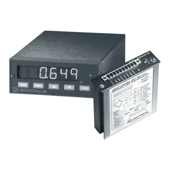
- Page 9 . SB.3 WITH NSTRUCTION ANUAL V 1. I NTRODUCTION HYSICAL AYOUT Study the following diagrams to acquaint yourself with the most important 3000PLUS front and rear elements. Fig. 2 Setup Limit Status 3000PLUS Front Indicators Indicators Display Panel Elements (see Section 3.B) (see Section 1.D)
- Page 10 1. I NTRODUCTION ANEL OUNTING You can easily mount the 3000PLUS instrument in your Remove the four screws (“B”) holding the bezel to own precut panel. See Fig. 5, below, for appropriate the instrument housing. cutout and hole dimensions. PANEL THICKNESS NOTE: YOU DO NOT NEED TO DISCONNECT THE SHOULD NOT EXCEED 1/8 INCH.
- Page 11 It may be set to a full scale of either ±5 or ±10 VDC, reading may be invalid. and is available at the rear of the 3000PLUS as both During normal instrument setup, the operator will be DC voltage and 4-20 mA output (see Section 2.D)
- Page 12 NOTE: As long as the module is properly communicat- normal run-time operation, without having to enter ing with the 3000PLUS meter (and the meter is pow- Setup Mode. This is the case even when limit monitor- ered up), the indicator light will be flashing.
- Page 13 RUN-TIME FUNCTION: Press to close (turn “ON”) the installed 5D78 module’s calibra- tion shunt for a POSITIVE upscale reading. The positive shunt will be closed only as long as the UP button is pressed. When the button is released, the 3000PLUS will resume normal measurement. For SHUNT CALIBRATION, see Section 4.E.* SETUP FUNCTION: When the operator is called on to adjust the displayed numeric value of a given setup parameter, this button is used to increase that number—in the...
- Page 14 3000PLUS 5D78 I . SB.3 WITH NSTRUCTION ANUAL V 1. I NTRODUCTION NTER ENTER RUN-TIME FUNCTIONS: 1. Releases any and all currently LATCHED LIMITS and their respective relay outputs (see also Section 5.E) 2. Resets PEAK CAPTURE function; clears any currently captured peak value by momentarily disabling and re-enabling peak capture (see Section 5.B).
- Page 15 Click Yes. ning the installation. Click the large button labelled “Click this but- Insert the CD supplied with your 3000PLUS and ton. . .” open the 3KPCNFG folder. 11. If you are prompted to add a new group, click Con- Double-click SETUP.EXE to begin the installation...
- Page 16 NTRODUCTION 13. To RUN the Configurator, go to your Windows Now you can run the Configurator by clicking popup Start menu, select Programs, and click on 3000PLUS Configurator in the Programs 3000PLUS Configurator. list. PLEASE NOTE THE CONFIGURATOR IS A MICROSOFT ACCESS 2000 RUNTIME PROGRAM.
- Page 17 1. I NTRODUCTION A SAMPLE CONFIGURATION is installed with the MSCOMM32.OCX and COMDLG32.OCX software, to let you see typical 3000PLUS setup (which are shared components). If in doubt, entries. Select Open... from the Configurator File answer No. menu and double-click on “SAMPLE.”...
- Page 18 PLEASE NOTE: Some of the wiring diagrams in this section show only the male connector head- ers on the rear of the 3000PLUS instrument (also shown in Fig. 3). Each connected wire or jumper is to be firmly secured to the corresponding SCREW TERMINAL of the terminal block (supplied with the meter) that plugs into the appropriate header.
- Page 19 PC and the 3000PLUS is over three feet in length. This will prevent electrical noise from causing The RS232 interface observes a fixed protocol of “break”...
- Page 20 EXCITATION lines at the 5D78 TWO-POINT (DEADWEIGHT) calibration of the CONNECTOR. It is recommended that the resistance 3000PLUS, it should be tied across Terminals 7 (CAL of the conductors not exceed 0.0001 of the bridge ENABLE) and 10 (CAL SENSE) of the Transducer Con- resistance.
Need help?
Do you have a question about the 3000PLUS and is the answer not in the manual?
Questions and answers