Table of Contents

Related Manuals for Carrier ComfortVu TB-24-HM


Summary of Contents for Carrier ComfortVu TB-24-HM
- Page 1 ComfortVu BACnet Thermostat Standard Model TB-24-HM (24 Vac model) Installation and Operation Guide CARRIER CORPORATION ©2019 A member of the United Technologies Corporation family · Stock symbol UTX · Catalog No. 11-808-723-01 · 5/22/2019...
-
Page 2: Table Of Contents
Table of Contents Overview ………………………………………………………………………………………………………………………………..…. 4 Specifications ………………………………………………………………………………………………………………………..… 5-6 TB-24-HM Dimensions ……………………………………...………………….……………………………………………………..… 7 Operating instructions ……………………………………………………………………………………………………………..…… 8 Quick guide …………………………………………………………………………………………………………………..…….. 8 Turning the thermostat ON and OFF……………………………………………………………………………………..…….. 9 Selecting temperature scale………………………………………………………………………………………………..….…. 9 Adjusting the Setpoint temperature (for 1 setpoint and 2 setpoints configurations) ………………………………….……. 9 Selecting system mode…………………………………………………………………………………………………….…..…... - Page 3 Table of Contents Technician Settings ……………………………………………………………………………………...….……………...…….… 47-62 P43 – Soft start in heat – cut-in temperature P87 – De-ice in heat time P44 – Soft start in heat – cut-out temperature P88 – De-ice in heat break time P45 – Cool differential band P89 –...
-
Page 4: Overview
As part of an MS/TP network of BACnet Thermostats that can be managed from a BMS front-end system ® As part of a BACnet MS/TP network connected to an Carrier BACnet router in an i-Vu system. The router’s control programs provide trending and alarming of the BACnet Thermostat’s data. -
Page 5: Specifications
Specifications Sensing Element: Range Accuracy Temperature 41° F to 95° F (5° C to 35° C) ±1.0° F (0.5° C) Humidity 10% to 90 % ±3.0% typical Motion Sensing: Sensor Type PIR, quad, omnidirectional Distance 16.4 feet (5m) Detection range (HxV) 90°... - Page 6 Specifications (cont.) Weight 4.8 oz (0.14 kg) Compliance United States of America: FCC CFR47, Chapter 1, Subchapter A, Part 15, Class B Canada: Industry Canada Compliant, ICES-003, Class B Europe: Mark, Low Voltage Directive: 2014/35/EU RoHS Compliant: 2011/65/EU Australia and New Zealand: C-Tick Mark, AS/NZS 61000-6-3 Title 24 compliant if connected to a BMS with custom programming for economizer fault detection.
-
Page 7: Tb-24-Hm Dimensions
TB-24-HM Dimensions - 7 -... -
Page 8: Operating Instructions
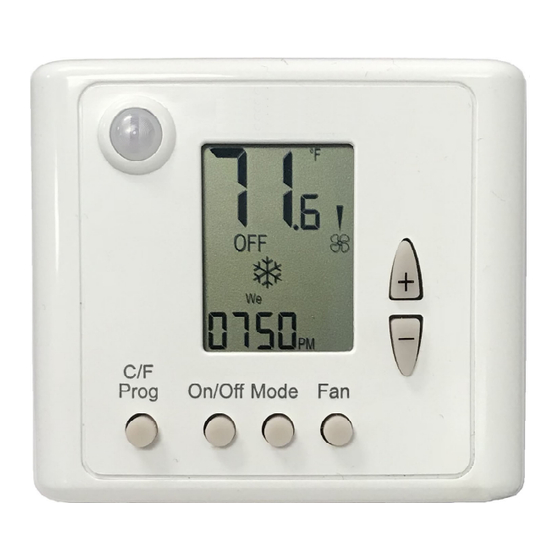
Operating instructions Quick guide Temperature/Humidity Fan speed indication: indications: Auto speed Temperature scale High Ambient Humidity Medium Setpoint adjust. Fan on demand Ambient/Setpoint indication temperature Indications: Ambient humidity indication Alarm Thermostat On/Off indication Button locked Program active System MODE indication: Program events indications: Fan only Cooling... -
Page 9: Turning The Thermostat On And Off
Operating instructions (cont.) Turning the thermostat ON and OFF Press the [On/Off] button to turn the thermostat ON or OFF. Selecting temperature scale Press the [C/F] button to switch between temperature scales. Celsius Fahrenheit Adjusting the Setpoint temperature In One setpoint configuration: 1. -
Page 10: Selecting System Mode
Operating instructions (cont.) Selecting system mode Press the [Mode] button to switch between system modes. Notes: During demand for cooling or heating, the active mode will flash. Cool Heat In Auto mode, the active mode icon (Cool or Heat) will appear on display. ... -
Page 11: Economy Mode
Operating instructions (cont.) Economy mode Economy by window contact Activate Economy mode by triggering a window contact, door switch, key-tag, remote economy switch, the built-in PIR sensor (passive infrared sensor), or through communication – binary value Economy by built-in PIR, by the remote economy switch, or through “UnoccupiedByNetwork”. -
Page 12: Economizer
Operating instructions (cont.) Economizer Economizer is used to reduce the energy consumed by the cooling systems, by using low external air temperatures to assist in the chilling process. When outdoor temperatures are lower relative to indoor (room) temperatures, the system utilizes the cool outdoor air as a free cooling source. -
Page 13: Weekly Program
Weekly program General Prior to programming, make sure that Technician Settings P107, P108, and P109 are configured correctly. Program types The thermostat can be configured to run four different types of weekly programs (set by Technician Setting P107): 7-day program with same settings for all days. ... - Page 14 Weekly program (cont.) Programming procedure The detailed programming procedure is described in the next sections. Make sure to follow the right programming procedure, suitable for the program type and features selected by Technician Settings. Press the [C/F - Prog] button to enter and proceed through the steps of the real time clock and ...
- Page 15 Weekly program (cont.) Adjusting “EU type” daily programs – Start time / Stop time Start time 1. Press the [C/F – Prog] button. The programmed weekday(s), “Prog 1” indicating the first program event of the day and the word “Start” will appear on display. The HOURS will flash.
- Page 16 Weekly program (cont.) Adjusting “US type” daily programs – Start time / Stop time / Mode / Fan speed / Setpoints Start time 1. Press the [C/F – Prog] button. The programmed weekday(s), “Prog 1” indicating the first program event of the day and the word “Start” will appear on display. The HOURS will flash.
- Page 17 Weekly program (cont.) Setpoint 1. Press the [C/F – Prog] button again. The setpoint will flash. Note: If the thermostat is configured to have two setpoints, first adjusts the setpoint for cooling and then the setpoint for heating. 2. Use the [+] and [-] buttons to select the system mode of the first event. Follow the steps above for the other schedule events of the same day ...
-
Page 18: Mac Address And Bacnet Device Instance Number
By default, the BACnet Device Instance Number is generated automatically by the thermostat (Vendor ID + MAC address). For example, Carrier’s vendor ID is 16, and if the MAC address is 075, the BACnet Device Instance Number is 16075. Note: If you change the MAC address, you must cycle the thermostat’s power to reset the BACnet Device Instance Number. -
Page 19: Installation
Installation Mount the BACnet Thermostat on an interior wall in the room to be controlled approximately 1.5 meters (5 feet) from the floor. Locate it where the occupant can easily read the LCD display and use the controls, and where the built-in PIR motion sensor can easily detect any movement in the room (see PIR detection area below). -
Page 20: Wiring Terminals
Wiring terminals For outputs 11-16, see Wiring and DIP switch/jumper settings (pages 25 through 39) For T1,0 inputs: Dry contact, 10 Vdc input, or 50 kOhm thermistor See Technician Setting P8 (page 41). MS/TP Communication (RS485): BACnet For IN1,0 inputs: Dry contact, 10 Vdc input, or 50 kOhm thermistor See Technician Setting P9 (page 42). -
Page 21: Dip Switch And Jumper Configurations
DIP switch and jumper configurations JP2JP3 JP2, JP3 – Outputs 15,16 – Analog or Digital SW4.1 – Without valves control in FC config. JP2 – Output 16 Enable = OFF (Open) Position 1 - Analog output Disable = ON (Closed) Position 3 - Digital output JP3 –... -
Page 22: Ac Configurations
AC configurations Find the configuration you want in the tables below, then find that configuration number (1 through 19) on the Wiring and DIP switch/ jumper settings pages starting on page 25. AC Configurations without humidification/dehumidification Outputs Configuration: Heat elements Compressors ●... -
Page 23: Fc Configurations For 2-Pipe Systems
FC configurations for 2-pipe systems Find the configuration you want in the tables below, then find that configuration number (20 through 30) on Wiring and DIP switch/ jumper settings pages starting on page 31. FC Configurations for 2-Pipe systems without humidification/dehumidification Outputs Configuration: ●... -
Page 24: Fc Configurations For 4-Pipe Systems / Floor Heating
FC configurations for 4-pipe systems / Floor heating Find the configuration you want in the tables below, then find that configuration number (31 through 47) on the Wiring and DIP switch/jumper settings pages starting on page 34. FC Configurations for 4-Pipe systems without humidification/dehumidification Outputs Configuration: ●... -
Page 25: Wiring And Dip Switch Configurations
Wiring and DIP switch/jumper configurations – AC systems Config. 1: Config. 2: Config. 3: Config. 4: HC32 HP42 HP22 HP21 Outputs 1 Speed fan 1 Speed fan 2/3 Speeds fan 2/3 Speeds fan Heat element 3 Heat element 2 Fan high Fan high stage heat) stage heat) - Page 26 Wiring and DIP switch/jumper configurations – AC systems Config. 5: Config. 6: Config. 7: HC21 HP11 HC11 2/3 Speeds fan Fan VFS Fan VFS Outputs Fan high Fan medium Economizer Economizer (or Economizer ) (option – SW1.6 ON) (option – SW1.6 ON) Fan low Heat element 2 Heat pump...
- Page 27 Wiring and DIP switch/jumper configurations – AC systems Config. 8: Config. 9: HC22 HP32 1 Speed fan, 1 Speed fan, Economizer Economizer Outputs Heat element Heat element 2 stage heat) stage heat) Economizer Economizer (option – SW1.6 ON) (option – SW1.6 ON) Fan (1 speed) Fan (1 speed) Compressor 2...
- Page 28 Wiring and DIP switch/jumper configurations – AC systems w/wo Humidifier for humidification, with Reheat for dehumidification Config. 10: Config. 11: Config. 12: Config. 13: HC22 HP31 HC11 HP21 1 Speed fan, 1 Speed fan, 2/3 Speeds fan, 2/3 Speeds fan, Humidifier, Humidifier, Humidifier,...
- Page 29 Wiring and DIP switch/jumper configurations – AC systems with Humidifier for humidification Config. 15: Config. 14: HP21 HC12 1 Speed fan, 1 Speed fan, Humidifier, Reheat for Humidifier Outputs Dehumidification Heat element Heat element stage heat) Economizer Economizer (option – SW1.6 ON) (option –...
- Page 30 Wiring and DIP switch/jumper configurations – AC systems with Humidifier for dehumidifier Config. 16: Config. 17: Config. 18: Config. 19: HC21 HC11 HP11 HP21 1 Speed fan, 1 Speed fan, 1 Speed fan, 1 Speed fan, Humidifier, Humidifier, Humidifier, Humidifier, Dehumidifier Dehumidifier Dehumidifier...
- Page 31 Wiring and DIP switch/jumper configurations – FC systems – 2-pipe Config. 20: Config. 21: Config. 23: Config. 22: 2-Pipe, 2-Pipe, 1/2/3 2-Pipe, 2-Pipe, 1/2/3 Speeds Speeds fan Fan VFS, Fan VFS Cool/Heat PID Cool/Heat PID Outputs Fan high Fan high Fan medium Fan medium Economizer...
- Page 32 Wiring and DIP switch/jumper configurations – FC systems – 2-pipe with Humidifier for humidification and Reheat for dehumidification Config. 25: Config. 24: Config. 27: 2-Pipe, Config. 26: 2-Pipe, 2-Pipe, 1/2/3 Speeds fan , 2-Pipe, 1/2/3 Speeds fan , Fan VFS, Cool/Heat PID, Fan VFS, Cool/Heat PID,...
- Page 33 Wiring and DIP switch/jumper configurations – FC systems – 2-pipe with Dehumidifier, w/wo Humidifier Config. 28: Config. 29: Config. 30: 2-Pipe, 2-Pipe, 2-Pipe, 1/2/3 Speeds fan , 1/2/3 Speeds fan , Fan VFS, Humidifier, Cool/Heat PID, Dehumidifier Dehumidifier Dehumidifier Outputs Fan high Fan high Fan medium...
- Page 34 Wiring and DIP switch/jumper configurations – FC systems – 4-pipe w/wo Floor heating Config. 34: Config. 31: Config. 32: Config. 33: 4-Pipe,1/2/3 4-Pipe, 4-Pipe, 1/2/3 4-Pipe, 1/2/3 Speeds fan , 1/2/3 Speeds Speeds fan , Speeds fan , Cool valve PID, Floor heating Cool valve PID Floor heating...
- Page 35 Wiring and DIP switch/jumper configurations – FC systems – 4-pipe Config. 36: Config. 37: Config. 38: Config. 35: 4-Pipe, 4-Pipe, 4-Pipe, 4-Pipe, 1/2/3 Speeds fan , Fan VFS, Fan VFS, Fan VFS Heat valve PID Heat valve PID Cool valve PID Outputs Fan high Economizer...
- Page 36 Wiring and DIP switch/jumper configurations – FC systems – 4-pipe Config. 39: 4-Pipe, 1/2/3 Speeds fan , Heat valve PID, Cool valve PID Outputs Fan high Fan medium (or Economizer ) Fan low Heat element stage heat) Cool valve PID Heat valve PID Jumpers JP2, JP3...
- Page 37 Wiring and DIP switch/jumper configurations – FC systems – 4-pipe with Reheat for dehumidification, without Humidifier Config. 41: Config. 40: 4-Pipe, 4-Pipe, 1/2/3 Speeds fan , 1/2/3 Speeds fan , Cool valve PID, Reheat for Reheat for Dehumidification Dehumidification Outputs Fan high Fan high Fan medium...
- Page 38 Wiring and DIP switch/jumper configurations – FC systems – 4-pipe with Humidifier, without Reheat for dehumidification Config. 43: Config. 44: Config. 42: 4-Pipe, 4-Pipe, 4-Pipe, 1/2/3 Speeds fan , 1/2/3 Speeds fan , 1/2/3 Speeds fan , Cool valve PID, Heat valve PID, Humidifier Humidifier...
- Page 39 Wiring and DIP switch/jumper configurations – FC systems – 4-pipe with Dehumidifier Config. 46: Config. 47: Config. 45: 4-Pipe, 4-Pipe, 4-Pipe, 1/2/3 Speeds fan , 1/2/3 Speeds fan , 1/2/3 Speeds fan , Cool valve PID, Heat valve PID, Dehumidifier Dehumidifier Dehumidifier Outputs...
-
Page 40: Technician Settings
Technician Settings Enter Technician Settings mode: 1. Adjust the setpoint temperature to 10ºC or 50ºF. 2. Press and hold the [C/F] button for 10 seconds to enter Technician Settings mode. “P01” will appear on display. View objects and make adjustments: Use the [Mode] button to step forward between different settings. - Page 41 Technician Settings (cont.) P05 – Enable/Disable the option to lock the [Mode] button “L1” + “ ” [Mode] button can be locked “L1” only [Mode] button cannot be locked Note: When enabled, press and hold both [-] and [Fan] buttons [Mode] [Mode] Cannot...
- Page 42 Technician Settings (cont.) P09 – Functionality of IN1,0 terminals “00” - IN1,0 terminals are not in use “01” - T2 (Change over sensor) * “02” - T3 (Soft start in heat sensor) ** “IN1,0” *T2 change over **T3 Soft start in “03”...
- Page 43 Technician Settings (cont.) P14 – Enable/Disable Auto change over mode “00” - Disable Auto change over mode “01” - Enable Auto change over mode Disable Enable Auto mode Auto mode P15 – Motion sensor logic (PIR) “00” - Thermostat turns off when unoccupied and back on when re-occupied.
- Page 44 Technician Settings (cont.) P19 – PIR (Motion sensor) polarity “00” - Normally open “01” - Normally closed Normally open Normally closed P25 – Economy setpoint for cooling Range: 5…35°C / 41…95°F. Default: 30°C / 86°F. EC setpoint in cooling (°C) (°F) P26 –...
- Page 45 Technician Settings (cont.) P30 – Beeper ON or OFF “01” - Beeper ON “00” - Beeper OFF Beeper Beeper P31 – P34 Fan on/off delay with fan on demand (auto fan) active. Time (sec.) Valve Fan ON Fan OFF delay delay P31 –...
-
Page 46: Technician Settings
Technician Settings (cont.) P35 – Enable/Disable Freeze protection “00” - Disable Freeze protection “01” - Enable Freeze protection Note: If enabled, freeze protection will start when the thermostat Disable freeze Enable freeze protection protection is either ON or OFF and regardless of the current system mode. -
Page 47: Technician Settings
Technician Settings (cont.) P43 – P44 Soft start in heat with fan on demand (auto fan) active. Heat valve Temp. Fan cut-out Fan cut-in temperature temperature P43 – Soft start in heat – cut-in temperature (FC Only!) The fan will not start before the temperature on T3 sensor reaches the cut-in temperature. - Page 48 Technician Settings (cont.) P45 – P46 Cool differential band / offset Room (with cool differential band offset = 0) Temp. Setpoint Compressor / Valve Cool differential band P45 – P46 Cool differential band / offset Room (with cool differential band offset ≠ 0) Temp.
- Page 49 Technician Settings (cont.) P47-48 Room Heat differential band / offset Temp. Setpoint (with heat differential band offset = 0) Heat differential band Compressor / Valve P47-48 Heat differential band / offset Room (with heat differential band offset ≠ 0) Temp. Setpoint Compressor / Valve Heat differential band...
- Page 50 Technician Settings (cont.) Shift between Cool and Heat Temp. in Auto change over mode Heat differential Cool differential (from cooling to heating) band band -0.5 +0.5 -0.5 +0.5 Compressor / Valve Setpoint Shift between Cool and Heat Shift between Cool and Heat Temp.
- Page 51 Technician Settings (cont.) P52 – Cool valve proportional band (FC Only!) Range: 2...10°C / 4...20°F Default: 2°C / 4°F Cool valve proportional band 0-10V Valve opening from fully closed to fully open. (°C) (°F) P53 – Cool proportional low limit (FC Only!) Range: 0...100% Default:...
- Page 52 Technician Settings (cont.) Fan turns ON when the Cool Fan ON or Heat valve reaches the “Proportional ON percent” Fan OFF Fan turns OFF when the Cool or Heat valve drops below the “Proportional OFF percent” Cool/Heat Valve % Proportional Proportional OFF percent ON percent...
- Page 53 Technician Settings (cont.) P65 – Fan VFS proportional band in cooling Range: 2...10°C / 4…20°F Default: 2°C / 4°F VFS Proportional band in cooling 0-10V fan speed from off closed to fully running. (°C) (°F) P66 – Fan VFS proportional band in heating Range: 2...10°C / 4…20°F Default: 2°C / 4°F...
- Page 54 Technician Settings (cont.) P71 – Fan VFS Medium speed percent in heating Range: 30...60% Default: VFS Med % in heating P72 – Fan VFS High speed percent in heating Range: 60...100% Default: VFS High % in heating Fan VFS Medium Fan VFS High Speed VFS Medium speed differential...
- Page 55 Technician Settings (cont.) P76 – Fan VFS Low limit in cooling Range: 0...100% Default: VFS low limit in cooling P77 – Fan VFS High limit in cooling Range: 0...100% Default: 100% VFS high limit in cooling P78 – Fan VFS Low limit in heating Range: 0...100% Default:...
- Page 56 Technician Settings (cont.) P83 – View T2 temperature sensor readings Note: If T2 is not connected, 0.0 will appear on display. T2 Sensor T2 Sensor Not connected readings P84 – View T3 temperature sensor readings Note: If T3 is not connected, 0.0 will appear on display. T3 Sensor T3 Sensor Not connected...
- Page 57 Technician Settings (cont.) P89 – De-ice in heat – cut-in temperature (AC only!) Range: -9.5…+8°C / 15...46°F Default: 0°C / 32°F The outdoor unit coil temperature in which de-icing will start. De-ice in heat (°C) (°F) P90 – De-ice in heat – cut-out temperature (AC only!) Range: 2...20°C / 35...68°F Default:...
- Page 58 Technician Settings (cont.) P101 – Screen dimming delay Range: 0...99 minutes Default: 5 minutes Screen dimming delay P107 – Weekly program configuration “00” - Disable weekly program “01” - 7 days with the same program “02” - One program for Monday to Friday and another program for Saturday and Sunday Weekly program “03”...
- Page 59 Technician Settings (cont.) P114 – Cool PID Kp (FC Only!) Range: 0...100% Default: 100% Cool PID P115 – Heat PID Kp (FC Only!) Range: 0...100% Default: 100% Heat PID P116 – Cool PID Ki (FC Only!) Range: 0...100% Default: Cool PID P117 –...
- Page 60 Technician Settings (cont.) P122 – Cool Proportional output threshold time (seconds) (FC Only!) Range: 0...100 seconds Default: 60 seconds Cool proportional cooling threshold P123 – Heat Proportional output threshold time (seconds) (FC Only!) Range: 0...100 seconds Default: 60 seconds Heat proportional cooling threshold P160 –...
- Page 61 Technician Settings (cont.) P189 – Dehumidification cycle in unoccupied mode Range: 0...600 minutes Default: 20 minutes Dehumidification cycle in unocc. mode P190 – Dehumidification break time in unoccupied mode Range: 0...900 minutes Default: 40 minutes Dehumidification break in unocc. mode P192 –...
-
Page 62: Technician Settings
Technician Settings (cont.) P196 – Dead zone between humidification and dehumidification Range: 0...100 %RH Default: 0 %RH Dead zone Hum./Dehum. P197 – Humidity setpoint Range: 20...100 %RH Default: 45 %RH Humidity setpoint P198 – Not in use Communication protocol indication P200 –... -
Page 63: Alarms And Indications
Alarms and Indications T1 Internal sensor or T1 External sensor fault De-icer in cool indication De-icer in heat indication Overheat in heat Overheat in cool Teconomizer sensor fault - 63 -... -
Page 64: Document Revision History
Document revision history Important changes to this document are listed below. Minor changes such as typographical or formatting errors are not listed. Date Topic Change description 05/22/19 Technician Settings: P03 Reversed numbers in the Setpoint Limit for Heating graphic 2/19/19 Specifications Changed Mounting specification description.
Need help?
Do you have a question about the ComfortVu TB-24-HM and is the answer not in the manual?
Questions and answers