INVENTOR U6MRS32-18 Service Manual
Air conditioning systems
Hide thumbs
Also See for U6MRS32-18:
- User manual (17 pages) ,
- Installation manuals (112 pages) ,
- Installation manual (108 pages)
Table of Contents
Advertisement
Quick Links
Advertisement
Chapters
Table of Contents
Troubleshooting

Related Manuals for INVENTOR U6MRS32-18


Summary of Contents for INVENTOR U6MRS32-18
- Page 1 AIR CONDITIONING SYSTEMS LCAC • SERVICE MANUAL ENGLISH...
-
Page 2: Table Of Contents
Table of Contents §. Safety Precautions Precautions Information servicing §. Model Reference & External Appearance Model Reference External Appearance §. Indoor Unit Indoor Unit - Compact Four-way Cassette Type Indoor Unit - A6 Duct Type Indoor Unit - Floor Ceiling Type §. - Page 3 Table of Contents §. Troubleshooting Safety Caution General Troubleshooting Complain Record Form Information Inquiry Error Diagnosis and Troubleshooting Without Error Code Quick Maintenance by Error Code Troubleshooting by Error Code Check Procedures §. Indoor Unit Disassembly Indoor Unit - Compact Four-way Cassette Type Indoor Unit - A6 Duct Type Indoor Unit - Floor Ceiling Type §.
-
Page 5: Precautions
Safety Precautions Contents Precautions ......................2 Information servicing(For flammable materials) ..........3... - Page 6 1. Precautions CAUTION To prevent personal injury, or property or unit damage, • • While unpacking be careful of sharp edges around adhere to all precautionary measures and instructions the unit as well as the edges of the fins on the con- denser and evaporator.
-
Page 7: Information Servicing
2. Information servicing(For • Prior to work taking place, the area around the equipment is to be surveyed to make sure that there are no flammable flammable materials) hazards or ignition risks. • NO SMOKING signs shall be displayed. Checks to the area Ventilated area •... - Page 8 • that capacitors are discharged: this shall be done in shall also take into account the effects of aging or a safe manner to avoid possibility of sparking; continual vibration from sources such as compressors or fans. • that there no live electrical components and wiring are exposed while charging, recovering or purging 2.13 Detection of flammable refrigerants the system;...
- Page 9 • The refrigerant charge shall be recovered into the • Before attempting the procedure ensure that: correct recovery cylinders. The system shall be flushed • mechanical handling equipment is available, if with OFN to render the unit safe. This process may required, for handling refrigerant cylinders;...
- Page 10 • Empty recovery cylinders are evacuated and, if • The recovered refrigerant shall be returned to the possible, cooled before recovery occurs. refrigerant supplier in the correct recovery cylinder, and the relevant Waste Transfer Note arranged. Do not • The recovery equipment shall be in good working mix refrigerants in recovery units and especially not in order with a set of instructions concerning the cylinders.
-
Page 11: Model Reference
Model Reference Contents Model Reference ....................2 External Appearance .....................3... - Page 12 Refer to the following table to determine the specific indoor and outdoor unit model number of your purchased equipment. Universal Outdoor Unit Capacity Indoor Unit Model Power Supply Model (Btu/h) Cassette V6MCRI32-18WiFiR A6 Duct V6MDI32-18WiFiR U6MRS32-18 1Φ, 220-240V~, 50Hz Floor Ceiling V6MKI32-18WiFiR Model Reference ...
-
Page 13: External Appearance
2. External Appearance Indoor Unit Compact Four-way Cassette A6 Duct Floor Ceiling Model Reference ... - Page 14 Outdoor Unit Outdoor Unit Model Reference ...
- Page 15 Indoor Unit-Compact Cassette Contents Feature........................2 Dimensional Drawings ..................4 Part names ......................5 Service Place ......................6 Accessories ......................7 Air Velocity and Temperature Distributions ............8 Capacity Tables ....................12 Noise Criterion Curves ..................18 Electrical Characteristics ..................20 Electrical Wiring Diagrams ..................20...
-
Page 16: Feature
1. Feature Compact design • The body size is 570×260×570mm, it’s just smaller than the ceiling board, so it’s very easy for installation and will not damage the decoration. The panel size is 647×50×647mm. • The hooks are designed in the four corners of the body, which can save installation space. Fire-proof Controller Box •... - Page 17 Fresh Air • Fresh air intake function brings you fresh and comfortable air feeling. Wired Controller(Optional) • Compared with infrared remote controller, wired controller can be fixed on the wall and avoid mislaying. It's mainly used for commercial zone and makes air conditioner control more convenient. Louver Position Memory (Standard for ERP models) •...
-
Page 18: Dimensional Drawings
2. Dimensional Drawings IDU-Compact Cassette 4 ... -
Page 19: Part Names
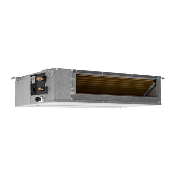
3. Part names Drain pump (within indoor unit) Drain pipe Air outlet Air inlet Front grille Louver Display panel Refrigerant pipe IDU-Compact Cassette 5 ... -
Page 20: Service Place
4. Service Place IDU-Compact Cassette 6 ... -
Page 21: Accessories
5. Accessories The air conditioning system comes with the following accessories. Use all of the installation parts and accessories to in- stall the air conditioner. Improper installation may result in water leakage, electrical shock and fire, or equipment failure. Name Shape Quantity Installation paper template (some... -
Page 22: Air Velocity And Temperature Distributions
6. Air Velocity and Temperature Distributions Discharge Angle 30° Cooling airflow velocity distributions Cooling temperature distributions IDU-Compact Cassette 8 ... - Page 23 Heating airflow velocity distributions Heating temperature distributions IDU-Compact Cassette 9 ...
- Page 24 Discharge Angle 60° Cooling airflow velocity distributions Cooling temperature distributions IDU-Compact Cassette 10 ...
- Page 25 Heating airflow velocity distributions Heating temperature distributions IDU-Compact Cassette 11 ...
-
Page 26: Capacity Tables
7. Capacity Tables Cooling V6MCRI32-18WiFiR+U6MRS32-18 ID WB 16.0 18.0 19.0 22.0 INDOOR (℃) OUTDOOR AIRFLOW DB(℃) ID DB (CMH) 23.0 25.0 27.0 30.0 23.0 25.0 27.0 30.0 23.0 25.0 27.0 30.0 23.0 25.0 27.0 30.0 (℃) 5.50 5.50 5.50 5.56 5.78... - Page 27 5.62 5.62 5.62 5.68 5.90 5.90 5.90 5.90 6.06 6.06 6.06 6.06 6.43 6.43 6.43 6.43 0.68 0.75 0.98 1.00 0.55 0.63 0.70 0.76 0.49 0.56 0.63 0.70 0.36 0.42 0.48 0.55 1.11 1.11 1.11 1.11 1.10 1.10 1.10 1.10 1.10 1.10 1.10...
- Page 28 V6MCRI32-18WiFiR + U6MRS32-18 ID WB 16.0 18.0 19.0 22.0 INDOOR (℃) OUTDOOR AIRFLOW DB(℃) ID DB (CMH) 23.0 25.0 27.0 30.0 23.0 25.0 27.0 30.0 23.0 25.0 27.0 30.0 23.0 25.0 27.0 30.0 (℃) 5.50 5.50 5.50 5.56 5.78 5.90 5.90...
- Page 29 5.74 5.74 5.80 5.86 6.05 6.05 6.05 6.05 6.20 6.20 6.20 6.20 6.57 6.57 6.57 6.57 0.70 0.78 1.00 1.00 0.56 0.64 0.72 0.98 0.49 0.57 0.66 0.73 0.35 0.42 0.49 0.57 1.26 1.26 1.26 1.26 1.25 1.25 1.25 1.25 1.26 1.26 1.26...
- Page 30 Heating V6MCRI32-18WiFiR + U6MRS32-18 [SI_Unit] HEATING PERFORMANCE AT INDOOR DRY BULB TEMPERATURE TC:TOTAL CAPACITY IN KILOWATTS (KW) PI:TOTAL POWER IN KILOWATTS (KW) INDOOR OUTDOOR AIRFLOW (CMH) Indoor Conditions (DB °C ) Indoor Conditions (DB °C ) DB(°C) 16.0 20.0 22.0 24.0...
- Page 31 V6MCRI32-18WiFiR+U6MRS32-18 [SI_Unit] HEATING PERFORMANCE AT INDOOR DRY BULB TEMPERATURE TC:TOTAL CAPACITY IN KILOWATTS (KW) PI:TOTAL POWER IN KILOWATTS (KW) INDOOR OUTDOOR AIRFLOW (CMH) Indoor Conditions (DB °C ) Indoor Conditions (DB °C ) DB(°C) 16.0 20.0 22.0 24.0 16.0 20.0 22.0...
-
Page 32: Noise Criterion Curves
-Sound level will vary depending on a range of factors such as the construction -(acoustic absorption coefficient) of particular room in which the equipment is installed. -The operating conditions are assumed to be standard. Noise level dB(A) Model Sound Power dB(A) V6MCRI32-18WiFiR 42.5 35.5 match with U6MRS32-18 IDU-Compact Cassette 18 ... - Page 33 V6MCRI32-18WiFiR NC-70 NC-60 NC-50 NC-40 NC-30 1000 2000 4000 8000 Band Center Frequency /Hz IDU-Compact Cassette 19 ...
-
Page 34: Electrical Characteristics
9. Electrical Characteristics Type 18000 Btu/h Phase 1-phase Frequency and Voltage 220-240V, 50Hz Circuit Breaker/ Fuse (A) 25/20 Indoor Unit Power Wiring (mm Outdoor Unit Power Wiring (mm 3×2.5 Ground Wiring Indoor/Outdoor Connecting Strong Electric Signal 4×1.0(4×2.5 with auxiliary electric heater) Wiring (mm Weak Electric Signal 10. - Page 35 Indoor unit wiring diagram: 16022500004023 16022500004023 NOTE: Inner Driver WIRING DIAGRAM FOR FAN MOTER Anti-cold air The wiring diagram TO WIRE SWITCH CONTROL THEN NO DC Motor NEWFAN Alarm Remote (INDOOR UNIT) POWER REQUEST. is for explanation CONTROLLER Output Control purpose only.
- Page 36 10.1 Some connectors introduce: A For remote control (ON-OFF) terminal port CN23 and short connector of JR6 1. Remove the short connector of JR6 when you use ON-OFF function; 2. When remote switch off (OPEN) ;the unit would be off; 3.
- Page 37 B For ALARM terminal port CN33 1. Provide the terminal port to connect ALARM ,but no voltage of the terminal port , the power from the ALARM system (not from the unit ) 2. Although design voltage can support higher voltage ,but we strongly ask you connect the power less than 24V, current less than 0.5A 3.
- Page 38 C. For new fresh motor terminal port CN8 1. Connect the fan motor to the port , no need care L/N of the motor ; 2. The output voltage is the power supply; 3. The fresh motor can not excess 200W or 1A , follow the smaller one ; 4.
- Page 39 10.2 Micro-Switch Introduce: A. Micro-switch SW1 is for selection of indoor fan stop temperature (TEL0) when it is in anti-cold wind action in heating mode. Range: 24 C, 15 C, 8 C, According to EEROM setting (reserved for special customizing). B.Micro-switch SW2 is for selection of indoor FAN ACTION if room temperature reaches the setponit and the compressor stops.
- Page 40 C.Micro-switch SW3 is for selection of auto-restart function. Range: Active, inactive SWITCH FOR MODE-PRIOR SETTING STATE COOL HEAT MODE HEAT COOL Factory Setting D. Micro-switch SW5 is for setting mode priority of multi connection. Range: Heat, cool. E.Micro-switch SW6 is for selection of temperature compensation in heating mode. This helps to reduce the real temperature difference between ceiling and floor so that the unit could run properly.
- Page 41 G.Micro-switch S1 and dial-switch S2 are for address setting when you want to control this unit by a central controller. Range: 00-63 32~35 36~53 54~71 72~90 91~105 106~140 141~160 161~200 H. Dial-switch ENC1: The indoor PCB is universal designed for whole series units from 7K to 68K. This ENC1 setting will tell the main program what size the unit is.
- Page 42 Indoor Unit-A6 Duct Contents Feature........................2 Dimensional Drawings ..................5 Part names ......................6 Service Place ......................6 Accessories ......................7 Fan Performance ....................8 Capacity Tables ....................10 Noise Criterion Curves ..................16 Electrical Characteristics ..................18 Electrical Wiring Diagrams ..................18...
-
Page 43: Feature
1. Feature Constant Air Volume Control With constant air volume control technology, optimal air flow cools every room consistently and accurately with both short pipes and long pipes. High Static Pressure Capable to be installed in various applications that requires static pressure of 160Pa. Ordinary 160Pa 160Pa... - Page 44 Slim Design The industry lowest height is designed to be fitted into tight roof space. 2 Types Installation Two types of installation methods can be selected: ceiling concealed and floor concealed(optional) Flexible Air Intake The frame size of air inlet in rear and bottom is the same. It’s very easy to switch to match different applications.
- Page 45 Built-in Drain Pump The built-in drain pump can lift condensing water up to 750mm. Communication Wire Connection For ordinary duct, 3 wires must correspond to P, Q and E terminal one by one. You may be confused when wires are too long. A6 duct uses two wires without polarity connection way, which almost has no mistake during the installation.
-
Page 46: Dimensional Drawings
2. Dimensional Drawings Model unit (KBtu/h) inch 34.65 8.27 26.54 23.62 5.51 27.8 1.97 5.35 30.79 7.48 1.57 36.22 3.07 5.83 3.46 4.41 IDU-A6 Duct 5 ... -
Page 47: Part Names
3. Part names Air inlet Electric control box Air lter(on some models) Drain hose Air outlet Refrigerant connecting pipe 4. Service Place Air outlet (30cm) 11.8 (20cm) Air inlet 23.6 x23.6 (60cmx60cm) checking orifice IDU-A6 Duct 6 ... -
Page 48: Accessories
5. Accessories The air conditioning system comes with the following accessories. Use all of the installation parts and accessories to in- stall the air conditioner. Improper installation may result in water leakage, electrical shock and fire, or equipment failure. Name Shape Quantity Soundproof / insulation sheath... -
Page 49: Fan Performance
6. Fan Performance IDU-A6 Duct 8 ... - Page 50 Constant air volume IDU-A6 Duct 9 ...
-
Page 51: Capacity Tables
7. Capacity Tables Cooling V6MDI32-18WiFiR + U6MRS32-18 ID WB 16.0 18.0 19.0 22.0 INDOOR (℃) OUTDOOR AIRFLOW DB(℃) ID DB (CMH) 23.0 25.0 27.0 30.0 23.0 25.0 27.0 30.0 23.0 25.0 27.0 30.0 23.0 25.0 27.0 30.0 (℃) 5.50 5.50 5.50... - Page 52 5.62 5.62 5.62 5.68 5.90 5.90 5.90 5.90 6.06 6.06 6.06 6.06 6.43 6.43 6.43 6.43 0.69 0.76 0.98 1.00 0.56 0.63 0.70 0.78 0.49 0.57 0.64 0.71 0.36 0.42 0.49 0.56 1.11 1.11 1.11 1.11 1.10 1.10 1.10 1.10 1.10 1.10 1.10...
- Page 53 Heating V6MDI32-18WiFiR + U6MRS32-18 [SI_Unit] HEATING PERFORMANCE AT INDOOR DRY BULB TEMPERATURE TC:TOTAL CAPACITY IN KILOWATTS (KW) PI:TOTAL POWER IN KILOWATTS (KW) INDOOR OUTDOOR AIRFLOW (CMH) Indoor Conditions (DB °C ) Indoor Conditions (DB °C ) DB(°C) 16.0 20.0 22.0 24.0...
-
Page 54: Noise Criterion Curves
-Sound level will vary depending on a range of factors such as the construction -(acoustic absorption coefficient) of particular room in which the equipment is installed. -The operating conditions are assumed to be standard. Sound Power Noise level dB(A) Model dB(A) V6MDI32-18WiFiR + U6MRS32-18 41.5 V6MDI32-18WiFiR IDU-A6 Duct 16 ... - Page 55 NC-70 NC-60 NC-50 NC-40 NC-30 1000 2000 4000 8000 Band Center Frequency /Hz IDU-A6 Duct 17 ...
-
Page 56: Electrical Characteristics
9. Electrical Characteristics Type 18000 Btu/h Phase 1-phase Frequency and Voltage 220-240V, 50Hz Circuit Breaker/ Fuse (A) 25/20 Indoor Unit Power Wiring (mm Outdoor Unit Power Wiring (mm 3×2.5 Ground Wiring Indoor/Outdoor Connecting Strong Electric Signal 4×1.0(4×2.5 with auxiliary electric heater) Wiring (mm Weak Electric Signal 10. - Page 57 Indoor unit wiring diagram: 16023000008817 16023000008817 FAN FOR THE WIRING DIAGRAM FRESH AIR NOTE: Alarm Remote OR ANION (INDOOR UNIT) FAN1 Output Control 1.The parts with dotted line indicates GENERATOR optional features. DC MOTOR CON2 DRIVER MODLE 2.Remove the short connector of J7 DC FAN when you use the "on-off"...
- Page 58 Field wiring diagram: 16022700001415 1(L) 2(N) S 1(L) 2(N) S Power supply: 1-Phase 208-240V~ 24K : 3-core cable 3x2.5mm ≤ 25K-36K : 3-core cable 3x4.0mm ≥ 37K : 3-core cable 3x6.0mm Wiring Diagrams ...
- Page 59 10.1 Some connectors introduce: A. For new fresh motor terminal port (also for Anion generator) CN43: 1. Connect the fan motor to the port, no need care L/N of the motor; 2. The output voltage is the power supply; 3. The fresh motor can not excess 200W or 1A, follow the smaller one; 4.
- Page 60 B For ALARM terminal port CN33 1. Provide the terminal port to connect ALARM, but no voltage of the terminal port, the power from the ALARM system (not from the unit); 2. Although design voltage can support higher voltage, but we strongly ask you connect the power less than 24V, current less than 0.5A;...
- Page 61 C. For remote control (ON-OFF) terminal port CN23 and short connector of J7 1. Remove the short connector of J7 when you use ON-OFF function; 2. When remote switch off (OPEN); the unit would be off; 3. When remote switch on (CLOSE); the unit would be on; 4.
- Page 62 10.2 Micro-Switch Introduce: FOR ANTI-COLD WIND EEPROM TEL0 DEFAULT FACTORY SETTING A. Micro-switch SW1 is for selection of indoor fan stop temperature (TEL0) when it is in anti-cold wind action in heating mode. Range: 24°C, 15°C, 8°C, according to EEROM setting (reserved for special customizing). FOR SETTING FAN MOTOR CONTROL WHEN THERE IS NO DEMAND MOD E...
- Page 63 FOR TEMP. COMPENSATION(HEATING) EEPROM CODE DEFAULT FACTORY SETTING D. Micro-switch SW6 is for selection of temperature compensation in heating mode. This helps to reduce the real temperature difference between ceiling and floor so that the unit could run properly. If the height of installation is lower, smaller value could be chosen.
- Page 64 Indoor Unit-Floor Ceiling Contents Feature........................2 Dimensional Drawings ..................3 Part names ......................4 Service Place ......................5 Accessories ......................6 Air Velocity and Temperature Distributions ............7 Capacity Tables ....................15 Noise Criterion Curves ..................19 Electrical Characteristics ..................21 Electrical Wiring Diagrams ..................22...
-
Page 65: Feature
1. Feature Easy installation- 2 Style Installation • Fashionable design and streamline appearance, suitable for different room style. 3D Airflow • Vertical air flow and horizontal airflow can be adjusted by remote controllerto direct air flow to every corner of the room. -
Page 66: Dimensional Drawings
2. Dimensional Drawings Model(KBtu/h) Unit 1068 inch 42.05 26.57 9.25 38.7 IDU-Floor Ceiling 3 ... -
Page 67: Part Names
3. Part names Installation part Louver grille Air outlet Display panel Air inlet IDU-Floor Ceiling 4 ... -
Page 68: Service Place
4. Service Place 35mm/1.38in IDU-Floor Ceiling 5 ... -
Page 69: Accessories
5. Accessories The air conditioning system comes with the following accessories. Use all of the installation parts and accessories to in- stall the air conditioner. Improper installation may result in water leakage, electrical shock and fire, or equipment failure. Name Shape Quantity Soundproof/insulation sheath... -
Page 70: Air Velocity And Temperature Distributions
6. Air Velocity and Temperature Distributions Ceiling installation: Discharge Angle 30° Cooling airflow velocity distributions Cooling temperature distributions IDU-Floor Ceiling 7 ... - Page 71 Ceiling installation: Discharge Angle 60° Cooling airflow velocity distributions Cooling temperature distributions IDU-Floor Ceiling 8 ...
- Page 72 Ceiling installation: Discharge Angle 30° Heating airflow velocity distributions Heating temperature distributions IDU-Floor Ceiling 9 ...
- Page 73 Ceiling installation: Discharge Angle 60° Heating airflow velocity distributions Heating temperature distributions IDU-Floor Ceiling 10 ...
- Page 74 Floor installation: Discharge Angle 30° Cooling airflow velocity distributions Cooling temperature distributions IDU-Floor Ceiling 11 ...
- Page 75 Floor installation: Discharge Angle 60° Cooling airflow velocity distributions Cooling temperature distributions IDU-Floor Ceiling 12 ...
- Page 76 Floor installation: Discharge Angle 30° Heating airflow velocity distributions Heating temperature distributions IDU-Floor Ceiling 13 ...
- Page 77 Floor installation: Discharge Angle 60° Heating airflow velocity distributions Heating temperature distributions IDU-Floor Ceiling 14 ...
-
Page 78: Capacity Tables
7. Capacity Tables Cooling V6MKI32-18WiFiR + U6MRS32-18 ID WB 16.0 18.0 19.0 22.0 INDOOR (℃) OUTDOOR AIRFLOW DB(℃) ID DB (CMH) 23.0 25.0 27.0 30.0 23.0 25.0 27.0 30.0 23.0 25.0 27.0 30.0 23.0 25.0 27.0 30.0 (℃) 5.50 5.50 5.50... - Page 79 5.62 5.62 5.68 5.74 5.90 5.90 5.90 5.90 6.06 6.06 6.06 6.06 6.43 6.43 6.43 6.43 0.71 0.80 0.98 1.00 0.57 0.66 0.74 0.83 0.50 0.58 0.67 0.75 0.35 0.42 0.50 0.58 1.11 1.11 1.11 1.11 1.10 1.10 1.10 1.10 1.10 1.10 1.10...
- Page 80 V6MKI32-18WiFiR + U6MRS32-18 [SI_Unit] HEATING PERFORMANCE AT INDOOR DRY BULB TEMPERATURE TC:TOTAL CAPACITY IN KILOWATTS (KW) PI:TOTAL POWER IN KILOWATTS (KW) INDOOR OUTDOOR AIRFLOW (CMH) Indoor Conditions (DB °C ) Indoor Conditions (DB °C ) DB(°C) 16.0 20.0 22.0 24.0 16.0...
-
Page 81: Noise Criterion Curves
-Sound level will vary depending on a range of factors such as the construction -(acoustic absorption coefficient) of particular room in which the equipment is installed. -The operating conditions are assumed to be standard. Noise level dB(A) Model Sound Power dB(A) V6MKI32-18WiFiR match 41.5 38.5 34.5 with U6MRS32-18 IDU-Floor Ceiling 19 ... - Page 82 V6MKI32-18WiFiR (match with U6MRS32-18 NC-70 NC-60 NC-50 NC-40 NC-30 1000 2000 4000 8000 Band Center Frequency /Hz IDU-Floor Ceiling 20 ...
-
Page 83: Electrical Characteristics
9. Electrical Characteristics Type 18000 Btu/h Phase 1-phase Frequency and Voltage 220-240V, 50Hz Circuit Breaker/ Fuse (A) 25/20 Indoor Unit Power Wiring (mm Outdoor Unit Power Wiring (mm 3×2.5 Ground Wiring Indoor/Outdoor Connecting Strong Electric Signal 4×1.0(4×2.5 with auxiliary electric heater) Wiring (mm Weak Electric Signal ... -
Page 84: Electrical Wiring Diagrams
10. Electrical Wiring Diagrams IDU Model IDU Wiring Diagram Field Wiring Diagram V6MKI32-18WiFiR 16022700002948 Abbreviation Paraphrase Yellow-Green Conductor CAP1 Indoor Fan Capacitor FAN1 Indoor Fan PUMP PUMP LIVE NEUTRAL TO CCM Comm.Bus Central Controller Indoor Room Temperature Coil Temperature of Indoor Heat Exchanger Super High Speed High Speed ... - Page 85 Indoor unit wiring diagram: 16022700002948 MAGNETIC 16022700002948 MAGNETIC RING RING WIRING DIAGRAM (INDOOR UNIT) FAN1 FAN2 FAN FOR THE Note1: FRESH AIR DC FAN DC FAN Alarm Remote OR ANION DC MOTOR This symbol indicates the element FOR ANTI-COLD WIND Output GENERATOR Control...
- Page 86 10.1 Some connectors introduce: A. For new fresh motor terminal port (also for Anion generator) CN43: 1. Connect the fan motor to the port, no need care L/N of the motor; 2. The output voltage is the power supply; 3. The fresh motor can not excess 200W or 1A, follow the smaller one; 4.
- Page 87 B For ALARM terminal port CN33 1. Provide the terminal port to connect ALARM, but no voltage of the terminal port, the power from the ALARM system (not from the unit); 2. Although design voltage can support higher voltage, but we strongly ask you connect the power less than 24V, current less than 0.5A;...
- Page 88 C. For remote control (ON-OFF) terminal port CN23 and short connector of J7 1. Remove the short connector of J7 when you use ON-OFF function; 2. When remote switch off (OPEN); the unit would be off; 3. When remote switch on (CLOSE); the unit would be on; 4.
- Page 89 10.2 Micro-Switch Introduce: FOR ANTI-COLD WIND EEPROM TEL0 DEFAULT FACTORY SETTING A. Micro-switch SW1 is for selection of indoor fan stop temperature (TEL0) when it is in anti-cold wind action in heating mode. Range: 24°C, 15°C, 8°C, according to EEROM setting (reserved for special customizing). FOR SETTING FAN MOTOR CONTROL WHEN THERE IS NO DEMAND MOD E...
- Page 90 Range: Active, inactive FOR TEMP. COMPENSATION(HEATING) EEPROM CODE default FACTORY SETTING D. Micro-switch SW6 is for selection of temperature compensation in heating mode. This helps to reduce the real temperature difference between ceiling and floor so that the unit could run properly. If the height of installation is lower, smaller value could be chosen.
- Page 91 Outdoor Unit Contents Dimensional Drawings ..................2 Service Place ......................9 Capacity Correction Factor for Height Difference ..........10 Noise Criterion Curves ..................16 Refrigerant Cycle Diagrams ................18 Electrical Wiring Diagrams ..................19...
-
Page 92: Dimensional Drawings
1. Dimensional Drawings Please check the corresponding dimensional drawing according to the panel plate. ODU Model Panel Plate U6MRS32-18 Outdoor Unit 2 ... - Page 93 Panel Plate B30 Outdoor Unit 3 ...
- Page 94 Panel Plate BA30 Outdoor Unit 4 ...
- Page 95 Panel Plate CA30 Outdoor Unit 5 ...
- Page 96 Panel Plate D30 Outdoor Unit 6 ...
- Page 97 Panel Plate E30 Outdoor Unit 7 ...
- Page 98 Panel Plate 590 Outdoor Unit 8 ...
-
Page 99: Service Place
2. Service Place Outdoor Unit 9 ... -
Page 100: Capacity Correction Factor For Height Difference
3. Capacity Correction Factor for Height Difference Capacity(Btu/h) Pipe Length (m) Cooling 0.973 0.948 0.936 Indoor Upper than Outdoor 0.995 0.983 0.958 0.945 Height difference 1.000 0.988 0.963 0.950 H (m) 1.000 0.988 0.963 0.950 Outdoor Upper than Indoor 0.988 0.963 0.950 Heating... - Page 101 Capacity Pipe Length (m) (Btu/h) Cooling 0.914 0.894 0.874 0.944 0.924 0.903 0.883 Indoor Upper than Outdoor 0.975 0.954 0.933 0.912 0.891 0.995 0.984 0.963 0.942 0.921 0.900 Height difference 1.000 0.989 0.968 0.947 0.926 0.905 H (m) 1.000 0.989 0.968 0.947 0.926...
- Page 102 Capacity Pipe Length (m) (Btu/h) Cooling 0.887 0.856 0.824 0.928 0.896 0.864 0.833 Indoor Upper than Outdoor 0.969 0.937 0.905 0.873 0.841 0.995 0.979 0.947 0.914 0.882 0.850 Height difference 1.000 0.984 0.951 0.919 0.886 0.854 H (m) 1.000 0.984 0.951 0.919 0.886...
- Page 103 Capacity Pipe Length (m) (Btu/h) Cooling 0.885 0.845 0.805 0.921 0.894 0.854 0.813 Indoor Upper than Outdoor 0.958 0.931 0.903 0.862 0.822 0.995 0.967 0.940 0.912 0.871 0.830 Height difference 1.000 0.972 0.945 0.917 0.876 0.834 H (m) 1.000 0.972 0.945 0.917 0.876...
- Page 104 Capacity Pipe Length (m) (Btu/h) Cooling 0.880 0.838 0.796 0.918 0.889 0.846 0.804 Indoor Upper than Outdoor 0.956 0.927 0.898 0.855 0.812 0.995 0.966 0.937 0.907 0.864 0.820 Height difference 1.000 0.971 0.941 0.912 0.868 0.824 H (m) 1.000 0.971 0.941 0.912 0.868...
- Page 105 Capacity Pipe Length (m) (Btu/h) Cooling 0.866 0.816 0.767 0.908 0.875 0.825 0.774 Indoor Upper than Outdoor 0.951 0.917 0.884 0.833 0.782 0.995 0.961 0.927 0.893 0.841 0.790 Height difference 1.000 0.966 0.931 0.897 0.846 0.794 H (m) 1.000 0.966 0.931 0.897 0.846...
-
Page 106: Noise Criterion Curves
-Sound level will vary depending on arrange off actors such as the construction (acoustic absorption coefficient) of particular room in which the equipment is installed. -The operating conditions are assumed to be standard. Model Sound Power dB(A) Noise level dB(A) U6MRS32-18 55.5 U6MRS32-18 Outdoor Unit 16 ... - Page 107 U6MRS32-18 Cooling Heating NC-70 NC-60 NC-50 NC-40 NC-30 NC-20 1000 2000 4000 8000 Band Center Frequency /Hz Outdoor Unit 17 ...
-
Page 108: Refrigerant Cycle Diagrams
5. Refrigerant Cycle Diagrams Pipe Size (Diameter:ø) Piping length (m/ft) Elevation (m/ft) mm(inch) Model No. Additional Refrigerant Liquid Rated Max. Rated Max. U6MRS32-18 12.7(1/2) 6.35(1/4) 5/16.4 30/98.4 20/65.6 12g/m (0.13oz/ft) Outdoor Unit 18 ... -
Page 109: Electrical Wiring Diagrams
6. Electrical Wiring Diagrams ODU Model ODU Wiring Diagram ODU Main Printed Circuit Board U6MRS32-18 16022000022493 17122000002718 Outdoor Unit 19 ... - Page 110 Outdoor unit wiring diagram: 16022000022493 Wiring Diagrams ...
- Page 111 Outdoor unit printed circuit board diagram: 17122000002718...
- Page 112 Name Meaning Earth: connect to Ground Power Supply N_in: connect to N-line (208-230V AC input) L_in: connect to L-line (208-230V AC input) CN16 S: connect to indoor unit communication HEAT1 CN17 connect to compressor heater, 208-230V AC when is ON 4-WAY CN60 connect to 4 way valve, 208-230V AC when is ON.
- Page 113 Installation Contents Installation Overview Location Selection Indoor Unit Installation Outdoor Unit Installation Drainage Pipe Installation Refrigerant Pipe Installation Vacuum Drying and Leakage Checking Additional Refrigerant Charge Engineering of Insulation Engineering of Electrical Wiring Test Operation...
- Page 114 1. Installation Overview Indoor Unit Indoor Unit Install the indoor unit Install the outdoor unit Install the drainpipe Evacuate the refrigeration system Connect the wires Connect the refrigerant pipes Install the panel Perform a test run (only for cassette type) ...
- Page 115 2. Location selection 2.1 Unit location selection can refer to installation manual. 2.2 DO NOT install the unit in the following locations: • Where oil drilling or fracking is taking place. • Coastal areas with high salt content in the air. •...
-
Page 116: Service Space
3. Indoor Unit Installation(Compact Cassette Type 3.1 Service space for indoor unit Suspension bolt pitch dimensions Body dimensions Decoration panel dimensions Refrigerant piping Suspension bolt (×4) Ceiling opening dimensions Hanger bracket Ceiling board 2. Drill 4 holes 5cm (2”) deep at the ceiling hook positions in the internal ceiling. - Page 117 3.3 Compact Cassette Panel Installation unit and the four sides of false ceiling are even. The 3.3.1 Remove the front grille bottom of the unit should be 24mm / 0.9in higher than ceiling board. 1. Slide the 2 grille hooks toward the middle of the Generally, L should be half the length of the suspension decoration panel.
- Page 118 3.3.6 Close the front grille, and close the two grille hooks. 3.3.3 Mount the grille Ensure that the buckles at the back of the grille be properly seated in the groove of the panel. 3.3.4 Connect the two wires of the panel to the main board of the unit.
- Page 119 3. Indoor Unit Installation(Duct) a 90° angle to the ceiling. 6. Secure the bolt using the included washers and nuts. 3.1 Service space for indoor unit 7. Install the four suspension bolts. Air outlet (30cm) 11.8 8. Mount the indoor unit with at least two people to (20cm) lift and secure it.
- Page 120 installing the indoor unit. Model(KBtu/h) Static Pressure(Pa) 0-60 0-100 24~55 0-160 Change the fan motor static pressure according to external duct static pressure. NOTE: 1.Do not put the connecting duct weight on the indoor unit. NOTE: All the figures in this manual are for demonstration purposes only.
- Page 121 3. Indoor Unit Installation(Floor MODEL(kBtu/h) Length of D (mm/inch) Length of E (mm/inch) Ceiling Type) 18~24 983/38.7 220/8.7 1200/47.2 220/8.7 3.1 Service space for indoor unit 36K~60K 1565/61.6 220/8.7 Wall-Mounted Installation 35mm/1.38in 3.3 Hang Indoor Unit 1. The installation of hanging screw bolts. •...
- Page 122 D. Refrigerant pipe connection (D.gas side) E. Refrigerant pipe connection (E. Liquid side) Drain point 8. Mount the indoor unit onto the hanging screw bolts with a block. Position the indoor unit on a flat level by using a level to Wall-Mounted Installation prevent leaks.
- Page 123 4. Outdoor unit installation 4.3 Install Outdoor Unit Fix the outdoor unit with anchor bolts(M10) 4.1 Service space for outdoor unit >60cm / 23.6” Fix with bolts Caution Since the gravity center of the unit is not at its physical center, so please be careful when lifting it with a sling.
- Page 124 For Vertical drainage pipe (The following table is for 5. Drainage Pipe Installation reference) Install the drainage pipe as shown below and take Reference measures against condensation. Improperly installation Allowable value of inner could lead to leakage and eventually wet furniture and maximum water Remark pipe...
- Page 125 ing pipe. • Each indoor unit of the system should be installed it. • The installation should be considering the conve- nience for future cleaning. • The correct installation will not cause converse water flow and the slope of the branch pipes can be adjusted freely •...
- Page 126 6. Refrigerant Pipe Installation 6.1 Maximum length and drop height Ensure that the length of the refrigerant pipe, the number of bends, and the drop height between the indoor and outdoor units meets the requirements shown in the following table. For North America, Australia and Europe 3D Inverter models: Max.
- Page 127 6.2 The procedure of connecting pipes • For horizontal refrigerant pipe, the distance be- tween supporters should not be exceed 1m. 1.Choose the pipe size according to the specification table. • For vertical refrigerant pipe, the distance between 2.Confirm the cross way of the pipes. supporters should not be exceed 1.5m.
- Page 128 7. Vacuum Drying and Leakage 4. Rain water might penetrate into pipeline during construction. Checking 7.1 Purpose of vacuum drying Procedures of special vacuum drying are as follows: • Eliminating moisture in system to prevent the phe- 1. Vacuum drying for 1 hour. nomena of ice-blockage and copper oxidation.
- Page 129 9 . Engineering of Insulation 8. Additional Refrigerant Charge • After the vacuum drying process is carried out, the 9.1 Insulation of refrigerant pipe additional refrigerant charge process need to be 1. Operational procedure of refrigerant pipe performed. insulation • The outdoor unit is factory charged with refrigerant.
- Page 130 insulation and cause easy aging of the material. Engineering of Electrical Wring 9.2 Insulation of drainage pipe 1. Highlights of electrical wiring installation 1. Operational procedure of refrigerant pipe • All field wiring construction should be finished by insulation qualified electrician. •...
- Page 131 4. Drainage Test 11. Test Operation a. Ensure the drainpipe flow smoothly. New buildings 1. The test operation must be carried should perform this test before finishing the ceiling. out after the entire installation has been b. Remove the test cover. Add 2000ml of water to the tank completed.
- Page 132 Maintenance Contents First Time Installation Check .................2 Refrigerant Recharge ....................4 Re-Installation .......................5 Indoor Unit ....................5 Outdoor Unit ....................7...
-
Page 133: First Time Installation Check
1. First Time Installation Check Air and moisture trapped in the refrigerant system affects To prevent air and moisture from affecting the air the performance of the air conditioner by: conditioner’s performance, the indoor unit, as well as the pipes between the indoor and outdoor unit, must be be •... - Page 134 Procedure: • If the pressure successfully reaches -0.1 MPa Tighten the flare nuts of the indoor and outdoor (14.5 Psi), fully close the Handle Lo valve, then units, and confirm that both the 2- and 3-way valves cease vacuum pump operations. are closed.
-
Page 135: Refrigerant Recharge
2. Refrigerant Recharge mA A Procedure: Close both 2- and 3-way valves. 3-way valves. Slightly connect the Handle Lo charge hose to the Operate the air conditioner in cooling mode to charge 3-way service port. the system with liquid refrigerant. Connect the charge hose to the valve at the bottom When the electronic scale displays the correct of the cylinder. -
Page 136: Re-Installation
3. Re-Installation Indoor Unit Collecting the refrigerant into the outdoor unit Procedure: Confirm that the 2- and 3-way valves are opened. Close the 3-way valve so that the gauge rests between 0.3 MPa (43.5 Psi) and 0.5 MPa (72.5 Psi). Connect the charge hose with the push pin of Handle Lo to the 3-way valve’s gas service port. - Page 137 Air purging with vacuum pump Procedure: • If the pressure successfully reaches -0.1 MPa Tighten the flare nuts of the indoor and outdoor (14.5 Psi), fully close the Handle Lo valve, then units, and confirm that both the 2- and 3-way valves cease vacuum pump operations.
-
Page 138: Outdoor Unit
Outdoor Unit Evacuation for the whole system Procedure: Wait for 5 minutes then check whether the gauge Confirm that the 2- and 3-way valves are opened. needle moves after turning off the vacuum pump. If Connect the vacuum pump to the 3-way valve’s the gauge needle moves backward, check whether service port. - Page 139 Refrigerant charging mA A Procedure: Close both 2- and 3-way valves. Fully open the Handle Lo manifold valve, 2- and 3-way valves. Slightly connect the Handle Lo charge hose to the 3-way service port. Operate the air conditioner in cooling mode to charge the system with liquid refrigerant.
- Page 140 Product Features Contents Display Function ....................2 Safety Features ......................5 Basic Functions .......................6 Table ......................6 Abbreviation ....................7 Fan Mode ......................7 Cooling Mode ....................7 Heating Mode(Heat Pump Units) ..............8 Auto-mode ....................9 Drying Mode ....................9 Forced Operation Function ................9 Timer Function ....................10 3.10 ECO Function ....................10 3.11 Auto-Restart Function ..................10 3.12 Drain Pump Control ..................10 Optional Functions ....................11...
-
Page 141: Display Function
1. Display Function Floor Ceiling Type MANUAL MANUAL MANUAL OPERATION OPERATION OPERATION TIMER TIMER TIMER PRE-DEF Infrared receiver (pre-heating/defrost) Timer indicator DEF./FAN DEF./FAN DEF./FAN ALARM ALARM ALARM indicator MANUAL Operation indicator Manual button Alarm indicator LED display Display 1 Display 2 PRE-DEF (pre-heating/defrost) Operation indicator... - Page 142 Super-slim Cassette Type Manual button Operation indicator Infrared receiver LED display Alarm indicator Timer indicator PRE-DEF (pre-heating/defrost) indicator Display 1 LED display Manual button FUNC Infrared receiver Operation indicator Alarm indicator Timer indicator PRE-DEF (pre-heating/defrost) indicator Display 2 Duct Type ...
- Page 143 Compact Cassette Type Console Type Infrared receiver Operation indicator Timer indicator PRE-DEF (pre-heating/defrost) indicator Manual button Note: Please select the display function according to your purchase product. Product Features ...
-
Page 144: Safety Features
2. Safety Features Inverter module protection The inverter module has an automatic shutoff mechanism Compressor three-minute delay at restart based on the unit’s current, voltage, and temperature. Compressor functions are delayed for up to ten seconds If automatic shutoff is initiated, the corresponding error upon the first startup of the unit, and are delayed for up code is displayed on the indoor unit and the unit ceases to three minutes upon subsequent unit restarts. -
Page 145: Basic Functions
3. Basic Functions Table Cooling Mode&Heating mode Heating Mode Functions Anti-cold Air Outdoor Fan Control Defrosting Mode Function Case 1: Case 1:T3 Case 2: Cases Compressor Case 2:T4 and T4,15 Case 1 Case 2 T3,10 min Frequency and T4 V6MDI32-18WiFiR Models V6MCRI32-18WiFiR V6MKI32-18WiFiR... -
Page 146: Abbreviation
Abbreviation limit frequency(FminC). • When protective time is more than or equal to ten Unit element abbreviations minutes. • When T1 is lower than or equal to (Tsc-CDIFTEMP). Abbreviation Element 3) If one of the following conditions is satisfied, not judge Indoor room temperature protective time. -
Page 147: Heating Mode(Heat Pump Units)
• For different outdoor units, the fan speeds are temperature T1 and indoor unit coil temperature different. Case 2: • The outdoor unit will be run at different fan speed according to T4. • For different outdoor units, the fan speeds are different. -
Page 148: Auto-Mode
3.5.3 Outdoor Fan Control: protection value, the compressor ceases operation. Case 1: Auto-mode • The outdoor unit will be run at different fan speed • This mode can be selected with the remote controller according to T4 and compressor frequency. and the temperature setting can be adjusted between •... -
Page 149: Timer Function
• Switch off setting automatically within 3 minutes after power returns. • Changes in: • mode 3.12 Drain Pump Control(Standard for • fan speed cassette type) • sleep mode • Use the water-level switch to control drain pump. • Follow me •... -
Page 150: Optional Functions
4. Optional Functions • Once active, the remote control will send a signal every 3 minutes, with no beeps. The unit automatically sets the temperature according to the measurements 8°C Heating from the remote control. In heating mode, the temperature can be set to as low •... -
Page 151: Remote Controller Functions
5. Remote Controller Functions 1. TEMP UP : Push this button to increase the indoor temperature setting in 1℃increments to 30℃ Infrared Wireless Remote Controller 2. TEMP DOWN : Push this button to decrease the indoor temperature setting in 1℃increments to 17℃. 5.1.1 RG51C/E(Standard for cassette) 3. - Page 152 5.1.2 RG57B2/BGE(Optional) the time setting in 30 minutes increments, up to 10 hours, then at 1 hour increments up to 24 hours. To cancel the Remote Controller Specifications Auto-off time setting, just press the button until the time setting is 0.0. Model RG57B2/BGE 12.
- Page 153 4. SLEEP: Select this function during the sleeping time. It Used to stop or start horizontal louver auto swing feature. keeps the most comfortable temperature and save energy. 11. SWING Button This function is available on COOL, HEAT or AUTO mode only.
-
Page 154: Lcd Wired Remote Controller
LCD Wired Remote Controller 5.2.1 LCD Wired Remote Controller KJR-12B/DP(T) The KJR-12B/DP(T) wired remote controller is standard for Duct type and is optional for other types. i) Buttons and Functions MODE BUTTON ON/OFF BUTTON • Used to start/stop the air •... - Page 155 iii) Installation • Dimensions 120mm 21mm 13.1mm (4.7”) (0.8”) (0.5”) 19.5mm (0.7”) 120mm 85.5mm (4.7”) (3.3”) 50mm (1.9”) • Wiring diagram Refer to the following diagram to wire the wall-mounted remote control to the indoor unit. Wire Joint, 5p Infrared Pipe 5-Core Shield Cable Indoor Unit Switch Board Indoor Unit...
- Page 156 Putty Trap Putty Putty Trap Trap Note: DO NOT allow water to enter the remote control. Use the trap and putty to seal the wires. • For exposed mounting, cut holes on four of the sides according to the picture below. Cut three holes Cut one holes for wire outlet...
- Page 157 5.2.2 LCD Wired Remote Controller KJR-120C/TF-E(Optional) The KJR-120C/TF-E wired remote controller is optional for all types. i) Buttons and Functions swing swing 1. POWER button 7. FOLLOW ME(PTC) button Turn on of turn off the unit. Allows the remote control to act as a remote thermostat and send temperature information from its current 2.
- Page 158 8 PTC function indication 1 Operation mode indication 9 C° / F° indication 2 Fan speed indication 10 Temperature display 3 Left-right swing indication 11 Lock indication 4 Up-down swing indication 12 Room temperature indication 5 Faceplate function indication 13 Clock display 6 Main unit and secondary unit indication 14 On/Off timer 7 Follow me function indication...
- Page 159 iii) Installation • Dimensions 18.5 • Wiring diagram Refer to the following diagram to wire the wall-mounted remote control to the indoor unit. Insert of the mainboard CN40 ----------------------------------- ----------------------------------- black black yellow ----------------------------------- yellow ----------------------------------- brown brown 4-Core Shield Cable, the length Wire controller Indoor unit mainboard is decided by installation...
- Page 160 Putty Trap Putty Putty Trap Trap Note: DO NOT allow water to enter the remote control. Use the trap and putty to seal the wires. • For exposed mounting, four outletting positions. There are three need cutting. Cutting place of right Cutting place of left Cutting place of top side wire outlet...
- Page 161 5.2.3 LCD Wired Remote Controller KJR-120G/TF-E(Optional) The KJR-120G/TF-E wired remote controller is optional for all types. i) Buttons and Functions Copy/ Swing Timer Back/Turbo Follow me Mode Fan speed (Lock) MODE button 7. DELAY/DAY OFF button Used to select the operation mode: Auto / Cooling / Drying / To set 1 to 2 hours delay off for each day or a whole day off Heating / Fan;...
- Page 162 ii) LCD Screen 8 Turbo/PTC function indication 1 Operation mode indication 9 C° / F° indication 2 Fan speed indication 10 Temperature display 3 Left-right swing indication 11 Lock indication 4 Up-down swing indication 12 Room temperature indication 5 Faceplate function indication 13 Clock display 6 Main unit and secondary unit indication 14 On/Off timer...
- Page 163 iii) Installation • Dimensions 120mm 18.5mm 46mm (4.7”) (0.7”) (1.8”) 83.5mm 123mm (3.3”) (4.8”) 62mm (2.4”) • Wiring diagram 3) Connection For Cassette: The wired controller connects to main control board directly. Main control board ADSS HA HB HA HB Wired controller For Duct, Ceiling&...
- Page 164 4) Address setting Unit1 Unit2 Unit16 HA HB HA HB HA HB HA HB Wired controller a. One non-polarity controller can control up to 16 indoor units. b. When the non-polarity controller is connected to several units, every air-conditioner in network has only one network address to distinguish each other.
- Page 165 Putty Trap Putty Putty Trap Trap Note: DO NOT allow water to enter the remote control. Use the trap and putty to seal the wires. • For wiring the indoor unit, there are three methods: • From the rear; • From the bottom; •...
-
Page 166: Centralized Controller
Centralized Controller 1) Connection For Light commercial air conditioner with XYE port, it can be directly connected to Centralized Controller (CCM03, CCM09). 2) Address setting When setting the address, please make sure the unit is powered off. The address can be set from 0 to 63 by the switch. Turn on the unit, then the address will be effective. -
Page 167: Using The Wire Controller To Set External Static Pressure
Using the wire controller to set Caution: external static pressure • If there is no change after airflow adjustment in the ventilation paths, be sure to reset automatic airflow • You can use the unit’s automatic airflow adjustment adjustment. function to set external static pressure. •... - Page 168 Troubleshooting Contents Safety Caution .......................3 General Troubleshooting ..................4 Complain Record Form ..................6 Information Inquiry ....................8 Error Diagnosis and Troubleshooting Without Error Code .......11 Remote maintenance ...................11 Field maintenance ..................12 Quick Maintenance by Error Code ..............17 Troubleshooting by Error Code ................18 E0 / F4 (EEPROM parameter error Diagnosis and Solution) ......18 E1 (Indoor and outdoor unit communication error Diagnosis and Solution) ..19 E3 / F5 (Fan speed is operating outside of the normal range Diagnosis and...
- Page 169 Troubleshooting Contents P0 (IPM Malfunction or IGBT Over-strong Current Protection Diagnosis and Solution) ......................27 P1 (Over Voltage or Too Low Voltage Protection Diagnosis and Solution) ..28 7.10 P4 (Inverter Compressor Drive Error Diagnosis and Solution) ......29 7.11 P6 (Low Pressure Protection Diagnosis and Solution) ........30 7.12 P7 (High Temperature Protection of IPM Module Diagnosis and Solution) ..31 Check Procedures ....................32...
-
Page 170: Safety Caution
1. Safety Caution WARNING Be sure to turn off all power supplies or disconnect all wires to avoid electric shock. While checking indoor/outdoor PCB, please equip oneself with antistatic gloves or wrist strap to avoid damage to the board. WARNING Electricity remains in capacitors even when the power supply is off. -
Page 171: General Troubleshooting
2. General Troubleshooting Error Display (Indoor Unit) When the indoor unit encounters a recognized error, the operation lamp will flash in a corresponding series, the timer lamp may turn on or begin flashing, and an error code will be displayed. These error codes are described in the following table: Operation Timer... - Page 172 For other errors: The display board may show a garbled code or a code undefined by the service manual. Ensure that this code is not a temperature reading. Troubleshooting: Test the unit using the remote control. If the unit does not respond to the remote, the indoor PCB requires replacement. If the unit responds, the display board requires replacement.
-
Page 173: Complain Record Form
3. Complain Record Form Complain Record Form Request No.: Date: Installation Date: Service Date: Customer Information Name Telephone No. Home Address Email Product Information Indoor Unit Model Outdoor Unit Model Serial No. of indoor unit Serial No. of outdoor unit Working Mode □Cooling □Heating... - Page 174 Parameter Checking information by Remote controller Displaying code Displaying code meaning Display value Display value meaning Room temperature Indoor coil temperature Outdoor coil temperature Ambient temperature Discharge temperature Targeted Frequency Actual Frequency Compressor current Outdoor AC voltage Indoor capacity test Reserve Outdoor fan speed EXV opening steps...
-
Page 175: Information Inquiry
4. Information Inquiry • To enter information inquiry status, complete the following procedure within 10 seconds: • Press LED 3 times. • Press SWING 3 times. • Finish 1 and 2 within 10 seconds, you will hear beeps for two seconds, which means the unit goes into parameter checking mode. - Page 176 Error code Display Error Information Indoor unit EEPROM parameter error Indoor / outdoor unit communication error The indoor fan speed is operating outside of the normal range Indoor room temperature sensor T1 is in open circuit or has short circuited Evaporator coil temperature sensor T2 is in open circuit or has short circuited Refrigerant leak detected Water-level alarm malfunction...
- Page 177 Anti-cold air in heating mode Evaporator coil temperature over high protection Evaporator coil temperature over low Protection PFC module malfunction Frequency limit caused by voltage Frequency limit caused by current Frequency limit caused by TP Frequency limit caused by T3 Frequency limit caused by T2 Frequency limit caused by PFC No error and protection...
-
Page 178: Error Diagnosis And Troubleshooting Without Error Code
5. Error Diagnosis and Troubleshooting Without Error Code WARNING Be sure to turn off unit before any maintenance to prevent damage or injury. Remote maintenance SUGGESTION: When troubles occur, please check the following points with customers before field maintenance. Problem Solution Unit will not start TS13 - TS14... -
Page 179: Field Maintenance
Field maintenance Problem Solution Unit will not start TS15 - TS16 Compressor will not start but fans run TS15 - TS16 Compressor and condenser (outdoor) fan will not start TS15 - TS16 Evaporator (indoor) fan will not start TS15 - TS16 Condenser (Outdoor) fan will not start TS15 - TS16 Unit runs, but shortly stops... - Page 180 1.Remote Maintenance Electrical Circuit Refrigerant Circuit Possible causes of trouble Unit will not start ☆ ☆ ☆ ☆ The power switch is on but fans will not start ☆ ☆ ☆ The temperature on the display board cannot be set ☆...
- Page 181 1.Remote Maintenance Others Possible causes of trouble Unit will not start The power switch is on but fans will not start ☆ The temperature on the display board cannot be set Unit is on but the wind is not cold(hot) Unit runs, but shortly stops The unit starts up and stops frequently ☆...
- Page 182 2.Field Maintenance Electrical Circuit Possible causes of trouble Unit will not start ☆ ☆ ☆ ☆ ☆ ☆ Compressor will not start but fans run ☆ ☆ ☆ ☆ ☆ Compressor and condenser (outdoor) fan will not start ☆ ☆ ☆...
- Page 183 2.Field Maintenance Refrigerant Circuit Others Possible causes of trouble Unit will not start Compressor will not start but fans run ☆ Compressor and condenser (outdoor) fan will not start Evaporator (indoor) fan will not start Condenser (Outdoor) fan will not start Unit runs, but shortly stops ☆...
-
Page 184: Quick Maintenance By Error Code
6. Quick Maintenance by Error Code If you do not have the time to test which specific parts are faulty, you can directly change the required parts according the error code. You can find the parts to replace by error code in the following table. Error Code Part requiring replacement Indoor PCB... -
Page 185: Troubleshooting By Error Code
7. Troubleshooting by Error Code E0 / F4 (EEPROM Parameter Error Diagnosis and Solution) Description: Indoor or outdoor PCB main chip does not receive feedback from EEPROM chip. Recommended parts to prepare: • Indoor PCB • Outdoor PCB Troubleshooting and repair: Shut off the power supply and turn it on 2 minutes later. -
Page 186: E1 (Indoor And Outdoor Unit Communication Error Diagnosis And Solution)
E1 (Indoor and Outdoor Unit Communication Error Diagnosis and Solution) Description: Indoor unit can not communicate with outdoor unit Recommended parts to prepare: • Indoor PCB • Outdoor PCB • Reactor Troubleshooting and repair: Power off, then restart the unit after 2 minutes. Does a problem remain? The unit is operating normally Measure Vs. - Page 187 Remarks: • Use a multimeter to test the DC voltage between 2 port(or S or L2 port) and 3 port(or N or S port) of outdoor unit. The red pin of multimeter connects with 2 port(or S or L2 port) while the black pin is for 3 port(or N or S port) . •...
-
Page 188: E3 / F5
E3 / F5 (Fan Speed Is Operating Outside of Normal Range Diagnosis and Solution) Description: When indoor / outdoor fan speed keeps too low or too high for a certain time, the unit ceases operation and the LED displays the failure. Recommended parts to prepare: •... - Page 189 Index: 1. Indoor or Outdoor DC Fan Motor(control chip is in fan motor) Power on and when the unit is in standby, measure the voltage of pin1-pin3, pin4-pin3 in fan motor connector. If the value of the voltage is not in the range showing in below table, the PCB must has problems and need to be replaced. Color Signal Voltage...
-
Page 190: Solution)
E4/E5/F1/F2/F3 (Open Circuit or Short Circuit of Temperature Sensor Diagnosis and Solution) Description: If the sampling voltage is lower than 0.06V or higher than 4.94V, the LED displays the failure. Recommended parts to prepare: • Connection wires • Sensors • PCB Troubleshooting and repair: Check the connection between temperature sensor and PCB. -
Page 191: Ec (Refrigerant Leakage Detection Diagnosis And Solution)
EC (Refrigerant Leakage Detection Diagnosis and Solution) Description: Define the evaporator coil temperature T2 of the compressor just starts running as Tcool. In the beginning 5 minutes after the compressor starts up, if T2 < Tcool-1°C(1.8°F) does not keep continuous 4 seconds and compressor running frequency higher than 50Hz does not keep for 3 minutes, and this situation happens 3 times, the display area will show “EC”... -
Page 192: Ee(Water-Level Alarm Malfunction Diagnosis And Solution)
EE(Water-Level Alarm Malfunction Diagnosis and Solution) Description: If the sampling voltage is not 5V, the LED displays the failure code. Recommended parts to prepare: • Connection wires • Water-level switch • Water pump • Indoor PCB Shut off the power supply and Shut off the power supply and turn it on 2 minutes later. -
Page 193: F0 (Current Overload Protection Diagnosis And Solution)
F0 (Overload Current Protection Diagnosis and Solution) Description: An abnormal current rise is detected by checking the specified current detection circuit. Recommended parts to prepare: • Outdoor PCB • Connection wires • Compressor Troubleshooting and repair: Check the power supply. Is it in working order? Stop the unit. -
Page 194: P0(Ipm Malfunction Or Igbt Over-Strong Current Protection Diagnosis And Solution)
P0(IPM malfunction or IGBT over-strong current protection Diagnosis and Solution) Description: When the voltage signal the IPM sends to the compressor drive chip is abnormal, the display LED shows “P0” and the AC turn off. Recommended parts to prepare: • Connection wires •... -
Page 195: P1(Over Voltage Or Too Low Voltage Protection Diagnosis And Solution)
P1(Over voltage or too low voltage protection Diagnosis and Solution) Description: Abnormal increases or decreases in voltage are detected by checking the specified voltage detection circuit. Recommended parts to prepare: • Power supply wires • IPM module board • PCB •... -
Page 196: P4(Inverter Compressor Drive Error Diagnosis And Solution)
7.10 P4(Inverter compressor drive error Diagnosis and Solution) Description: An abnormal inverter compressor drive is detected by a special detection circuit, including communication signal detection, voltage detection, compressor rotation speed signal detection and so on. Recommended parts to prepare: • Connection wires •... -
Page 197: P6(Low Pressure Protection Diagnosis And Solution)
7.11 P6(Low Pressure Protection Diagnosis and Solution) Description: If the sampling voltage is not 5V, the LED displays a failure code. Recommended parts to prepare: • Connection wires • Low pressure protector • Indoor fan assembly • Outdoor PCB Troubleshooting and repair: Low pressure protection Low pressure protection Are the low pressure protector... -
Page 198: P7(High Temperature Protection Of Ipm Module Diagnosis And Solution)
7.12 P7(High temperature protection of IPM module Diagnosis and Solution) Description: If the temperature of IPM module is higher than a certain value, the LED displays the failure. Recommended parts to prepare: • Outdoor PCB • IPM module board Troubleshooting and repair: Check the fastening screws on the PCB and IPM radiator. -
Page 199: Check Procedures
8. Check Procedures 8.1 Temperature Sensor Check WARNING Be sure to turn off all power supplies or disconnect all wires to avoid electric shock. Operate after compressor and coil have returned to normal temperature in case of injury. 1. Disconnect the temperature sensor from PCB (Refer to Chapter 5&6. Indoor&Outdoor Unit Disassembly). 2. - Page 200 Resistance Value KSN140D21UFZ Blue-Red Blue-Black 1.28Ω Red-Black Note: The picture and the value are only for reference, actual condition and specific value may vary. Troubleshooting 33 ...
- Page 201 8.3 IPM Continuity Check WARNING Electricity remains in capacitors even when the power supply is off. Ensure the capacitors are fully discharged before troubleshooting. 1. Turn off outdoor unit and disconnect power supply. 2. Discharge electrolytic capacitors and ensure all energy-storage unit has been discharged. 3.
- Page 202 Indoor Unit Disassembly-Compact Cassette Contents Indoor Unit Disassembly ..................1 Front Panel and Display Board................2 Electrical Parts ....................5 Fan Motor and Fan ..................7 Water Pump ....................9 Evaporator ....................11...
-
Page 203: Indoor Unit Disassembly
1. Indoor Unit Disassembly Front Panel and Display Board Procedure Illustration 1) Release 2 hooks and open the panel. CJ_MCA_001 ) (see CJ_MCA_001 2) Remove two screws of wire line. (see CJ_MCA_002 ) CJ_MCA_002 Note: This section is for reference only. Actual unit appearance may vary. ... - Page 204 Procedure Illustration 3) Release the hook then pull up the filter(see CJ_MCA_003 ) CJ_MCA_003 4) Remove 4 screws of cover and remove CJ_MCA_004 ) the display board(see CJ_MCA_004 Note: This section is for reference only. Actual unit appearance may vary. ...
- Page 205 Procedure Illustration 5) Remove 2 screws of display board and remove PCB.(see CJ_MCA_005 ) CJ_MCA_005 Note: This section is for reference only. Actual unit appearance may vary. Indoor Unit Disassembly 4 ...
- Page 206 Electrical Parts(Antistatic gloves must be worn.) Note: Remove the front panel (refer to 1.1 Front Panel and display) before disassembling electrical parts. Procedure Illustration 1) Remove 4 screws of the panel and pull up the panel. (see CJ_ MCA_006) CJ_MCA_006 2) Remove 3 screws of electrical cover.
- Page 207 Procedure Illustration 3) Disconnect the connectors of PCB. CJ_MCA_008 ) (see CJ_MCA_008 4) Remove 2 screws of main control board and remove PCB.(see MCA_009 ) CJ_MCA_009 5) Remove 2 screws of electronic control box and remove electronic CJ_MCA_010 ) control box.(see CJ_MCA_010 Note: This section is for reference only.
-
Page 208: Fan Motor And Fan
Fan motor and fan Note: Remove the front panel and electrical parts (refer to 1.1 &1.2 ) before disassembling fan motor. Procedure Illustration 1) Remove 4 screws of water collector then remove it.(see CJ_MCA_011 ) CJ_MCA_011 2) Remove the nut of the fan and then CJ_MCA_012 ) pull up the fan.(see CJ_MCA_012... - Page 209 Procedure Illustration 3) Remove the nuts and remove the fan motor(see CJ_MCA_013 ) CJ_MCA_013 Note: This section is for reference only. Actual unit appearance may vary. Indoor Unit Disassembly 8 ...
-
Page 210: Water Pump
Water Pump Note: Remove the front panel, electrical parts and water collector (refer to 1.1,1.2 &1.3) before disassembling water pump. Procedure Illustration 1) Take off the fasten belt of the water pump. (see CJ_MCA_014) CJ_MCA_014 2) Pinch the metal wire in the direction shown in the figure to release it. - Page 211 Procedure Illustration 3) Remove 3 screws and then remove the water pump. (see CJ_MCA_016) CJ_MCA_016 Note: This section is for reference only. Actual unit appearance may vary. Indoor Unit Disassembly 10 ...
-
Page 212: Evaporator
Evaporator Note: Remove the front panel, electrical parts and fan(refer to 1.1,1.2 &1.3) before disassembling evaporator. Procedure Illustration 1) Remove 3 screws of pipe clamp board assembly then remove it.(see CJ_MCA_017 ) CJ_MCA_017 2) Remove 4 screws of evaporator fixing board then remove it.(see MCA_018 ) CJ_MCA_018 Note: This section is for reference only. - Page 213 Procedure Illustration 3) Remove 1 screw of evaporator fixing CJ_MCA_019 ) hook and remove it. (see CJ_MCA_019 Note: This section is for reference only. Actual unit appearance may vary. Indoor Unit Disassembly 12 ...
- Page 214 Indoor Unit Disassembly -A6 DUCT Contents Indoor Unit Disassembly ..................1 Electrical Parts ....................2 Fan Motor and Fan ..................5 Evaporator .....................7...
- Page 215 1. Indoor Unit Disassembly Electrical Parts (Antistatic gloves must be worn.) Procedure Illustration 1) Remove 5 screws of the cover of electronic control box and then remove the cover. (see CJ_A6_001) CJ_A6_001 2) Remove 2 screws of the electronic control box. Then release 2 hooks of the main control board.
- Page 216 Procedure Illustration 3) Disconnect the connectors and then remove the front main control board. (see CJ_A6_003) 4) Turn over the electronic control box. CJ_A6_003 Disconnect the connectors and remove 2 screws of rear main control board. (see CJ_A6_004) CJ_A6_004 Note: This section is for reference only. Actual unit appearance may vary. ...
- Page 217 Procedure Illustration 5) Remove 2 screws of reactor and remove the reactor. (see CJ_A6_005) CJ_A6_005 Note: This section is for reference only. Actual unit appearance may vary. Indoor Unit Disassembly 4 ...
- Page 218 Fan motor and fan Procedure Illustration 1) Remove 10 screws of the top cover and then remove the top cover. (see CJ_A6_006) CJ_A6_006 2) Release 3 hooks of volute shell. (see CJ_A6_007) CJ_A6_007 Note: This section is for reference only. Actual unit appearance may vary. ...
- Page 219 Procedure Illustration 3) Remove the fiing screws of fan (2 screws). (see CJ_A6_008) CJ_A6_008 Note: This section is for reference only. Actual unit appearance may vary. Indoor Unit Disassembly 6 ...
- Page 220 Evaporator Procedure Illustration 1) Remove 9 Screws of the water collecter and remove the water collecter. (see CJ_A6_009) CJ_A6_009 2) Remove the screws of the pipe clamp board and the left side board (3 for the pipe clamp and 9 for left side board). (see CJ_A6_010) CJ_A6_010 Note: Remove the front panel (refer to 1.
- Page 221 Procedure Illustration 3) Remove 2 screws of the evaporator support and then pull up the temperature sensor. (see CJ_A6_011) CJ_A6_011 4) Remove the screw of the evaporator and then remove it. (see CJ_A6_012) CJ_A6_012 Note: This section is for reference only. Actual unit appearance may vary. ...
- Page 222 Indoor Unit Disassembly-Floor Ceiling Contents Indoor Unit Disassembly ..................1 Front Panel ....................2 Electrical Parts ....................3 Fan Motor and Fan ..................4 Evaporator .....................7 Display Board ....................11...
-
Page 223: Indoor Unit Disassembly
1. Indoor Unit Disassembly Front Panel Procedure Illustration 1) Remove 2 screws of return air grille subassembly and release 2 hooks. (see CJ_FC_001) CJ_FC_001 2) Release 2 hooks for each filter, and then pull up the filter. (see CJ_FC_002) CJ_FC_002 Note: This section is for reference only. - Page 224 Electrical Parts (Antistatic gloves must be worn.) Note: Remove the front panel (refer to 1.1 front panel) before disassembling electrical part. Procedure Illustration 1) Remove 4 screws of the cover of electronic control box and then remove the cover. (see CJ_FC_003) CJ_FC_003 2) Disconnect the connectors and then remove the main control board.
-
Page 225: Fan Motor And Fan
Fan motor and fan Note: Remove the front panel (refer to 1.1 front panel) before disassembling fan motor and fan. Procedure Illustration 1) Remove the fix screw of supporting board. (see CJ_FC_005) CJ_FC_005 2) Remove the screws of fan motor support and then remove the screw of ground wire. - Page 226 Procedure Illustration 3) Remove the two screws of the fan motor shaft. (see CJ_FC_007) CJ_FC_007 4) Release the hooks of the volute shell and then pull up it. (see CJ_FC_008) CJ_FC_008 Note: This section is for reference only. Actual unit appearance may vary. ...
- Page 227 Procedure Illustration 5) Remove the screws of fan (3 screws). (see CJ_FC_009) CJ_FC_009 Note: This section is for reference only. Actual unit appearance may vary. Indoor Unit Disassembly 6 ...
-
Page 228: Evaporator
Evaporator Note: Remove the front panel (refer to 1.1 front panel) before disassembling evaporator. Procedure Illustration 1) Remove the screws of left and right panel and then push it in the direction shown in the figure to move it. (see CJ_FC_010) CJ_FC_010 2) Remove the screws of the front panel(9 screws). - Page 229 Procedure Illustration 3) Remove the 1 screw of the water collector. (see CJ_FC_012) CJ_FC_012 4) Remove 3 screws of board and then remove it. (see CJ_FC_013) CJ_FC_013 Note: This section is for reference only. Actual unit appearance may vary. Indoor Unit Disassembly 8 ...
- Page 230 Procedure Illustration 5) Remove the screws of the pipe clamp board. (see CJ_FC_014) CJ_FC_014 6) Pull up the temperature sensor. (see CJ_FC_015) CJ_FC_015 Note: This section is for reference only. Actual unit appearance may vary. Indoor Unit Disassembly 9 ...
- Page 231 Procedure Illustration 7) Remove the screws of the front evaporator support. (5 screws) (see CJ_FC_016) CJ_FC_016 8) Remove the screws of the rear evaporator support then pull out the evaporator. (4 screws) (see CJ_ FC_017) CJ_FC_017 9) Remove 2 screws and Remove step motor.
-
Page 232: Display Board
Display Board Procedure Illustration 1) Remove 2 screws of display board and remove the display. (see CJ_ FC_019) CJ_FC_019 Note: This section is for reference only. Actual unit appearance may vary. Indoor Unit Disassembly 11 ... - Page 233 Outdoor Unit Disassembly Contents Outdoor Unit Table ....................2 Outdoor Unit Disassembly ..................3 Panel Plate .....................3 Electrical Parts .....................19 Fan Assembly ....................30 Fan Motor ....................31 Sound Blanket .....................32 Four-way Valve ....................33 Compressor ....................34...
-
Page 234: Outdoor Unit Table
1. Outdoor Unit Disassembly Outdoor Unit Table Outdoor Unit Model Panel Plate PCB Board U6MRS32-18 PCB Board 4 Outdoor Unit Disassembly 2 ... -
Page 235: Panel Plate
2. Outdoor Unit Disassembly 2.1 Panel Plate 1. BA30 Procedure Illustration Big Handle 1) Turn off the air conditioner and the power breaker. 2) Remove the screws of the big handle and then remove the big handle (1 screws) (see CJ_BA30_001). CJ_BA30_001 Top Cover 3) Remove the screws of the top cover... - Page 236 Procedure Illustration 4) Remove the screws of the front panel and then remove the front panel (7 screws) (see CJ_BA30_003). Front Panel CJ_BA30_003 5) Remove the screws of water collecting Water Collecting Cover cover (1 screw) (see CJ_BA30_004). CJ_BA30_004 Note: This section is for reference only. Actual unit appearance may vary. ...
- Page 237 Procedure Illustration 6) Remove the screws of the rear net and then remove the rear net (2 (for some screws) (see CJ_BA30_005). models) CJ_BA30_005 7) Remove the screws of the right panel and then remove the right panel (6 screws) (see CJ_BA30_006). Right Panel CJ_BA30_006 Note: This section is for reference only.
- Page 238 2. B30 Procedure Illustration 1) Turn off the air conditioner and the power breaker. Big Handle 2) Remove the screws of the big handle and then remove the big handle (1 screws) (see CJ_B30_001). CJ_B30_001 Top Cover 3) Remove the screws of the top cover and then remove the top cover (3 screws).
- Page 239 Procedure Illustration 4) Remove the screws of the front panel and then remove the front panel (8 screws) (see CJ_B30_003). Front Panel CJ_B30_003 5) Remove the screws of water collecting cover and then remove the water collecting cover (1 screw) (see CJ_ Water Collecting Cover B30_004).
- Page 240 Procedure Illustration 6) Remove the screws of the rear net and then remove the rear net (2 screws) CJ_B30_005). (for some models) (see CJ_B30_005 7) Remove the screws of the right panel and then remove the right panel (5 screws) (see CJ_B30_006). Right Panel CJ_B30_006 Note: This section is for reference only.
- Page 241 3. CA30 Procedure Illustration 1) Turn off the air conditioner and the power breaker. 2) Remove the screws of the big handle and then remove the big handle Big Handle (1 screws) (see CJ_CA30_001). CJ_CA30_001 Top Cover 3) Remove the screws of the top cover and then remove the top cover (3 screws).
- Page 242 Procedure Illustration 4) Remove the screws of the front panel and then remove the front panel (7 screws) (see CJ_CA30_003). Front Panel CJ_CA30_003 5) Remove the screws of water collecting cover and then remove the water collecting cover (1 screw) (see CJ_ CA30_004).
- Page 243 Procedure Illustration 6) Remove the screws of the rear net and then remove the rear net (2 screws) CJ_CA30_005). (for some (see models) CJ_CA30_005 7) Remove the screws of the right panel and then remove the right panel (7 screws) (see CJ_CA30_006). Right Panel CJ_CA30_006 Note: This section is for reference only.
- Page 244 4. D30 Procedure Illustration 1) Turn off the air conditioner and the Big Handle power breaker. 2) Remove the screws of the big handle and then remove the big handle (2 screws) (see CJ_D30_001). CJ_D30_001 3) Remove the screws of the top cover and then remove the top cover (4 Top Cover screws).
- Page 245 Procedure Illustration 4) Remove the screws of the front right panel and then remove the front right panel (2 screws) (see CJ_D30_003). Front Right Panel CJ_D30_003 5) Remove the screws of the front panel and then remove the front panel (9 screws) (see CJ_D30_004).
- Page 246 Procedure Illustration 6) Remove the screws of water collecting cover and then remove the water collecting cover (2 screw) (see CJ_ D30_005). Water Collecting Cover CJ_D30_005 7) Remove the screws of the rear net and then remove the rear net (2 screws) CJ_D30_006).
- Page 247 Procedure Illustration 8) Remove the screws of the right panel and then remove the right panel (8 screws) (see CJ_D30_007). Right Panel CJ_D30_007 Note: This section is for reference only. Actual unit appearance may vary. Outdoor Unit Disassembly 15 ...
- Page 248 4. E30/590 Procedure Illustration 1) Turn off the air conditioner and the power breaker. 2) Remove the screws of the big handle and then remove the big handle (2 screws) (see CJ_E30_001). CJ_E30_001 3) Remove the screws of the top cover and then remove the top cover (4 screws).
- Page 249 Procedure Illustration 5) Remove the screws of the front right panel and then remove the front right panel (2 screws) (see CJ_E30_004). CJ_E30_004 Note: This section is for reference only. Actual unit appearance may vary. Outdoor Unit Disassembly 17 ...
- Page 250 Procedure Illustration 1) Remove the screws of the front panel and then remove the front panel (7 screws) (see CJ_E30_005). CJ_E30_005 2) Remove the screws of the right panel and then remove the right panel (10 screws) (see CJ_E30_006). CJ_E30_006 Note: This section is for reference only.
- Page 251 Electrical parts Antistatic gloves must be worn when you disassemble the electronic box. WARNING: Note: Remove the air outlet grille(refer to 3.1 Panel Plate) before disassembling electrical parts. PCB for ON-OFF Models 1. PCB board 1 Procedure Illustration 1) Remove the two screws fixed the electronic control board (see CJ_ ODU_PCB_001).
- Page 252 Procedure Illustration 8) For models with subzero refrigeration control board, remove 3 screws of it showed in the figure. CJ_ODU_PCB_001-03 9) The subzero refrigeration control board is in the back of the medal sheet. CJ_ODU_PCB_001-04 Note: This section is for reference only. Actual unit appearance may vary. ...
- Page 253 2. PCB board 2 Procedure Illustration 1) Disconnect the power transformer (see CJ_ODU_010) 2) Disconnect the wires connected to terminals. (see CJ_ODU_010) 3) Disconnect the wires connected to contactor. (see CJ_ODU_010) 4) Disconnect the wires connected to T3/T4 sensor. (see CJ_ODU_010) CJ_ODU_PCB_002-1 Capacitor of Fan Motor Note: This section is for reference only.
- Page 254 3. PCB board 3 Procedure Illustration 1) Disconnect the wires connected to the transformer. (see CJ_ODU_ PCB_003-1) 2) Disconnect the wires connected to high/low pressure switch. (see CJ_ ODU_PCB_003-1 3) Disconnect the wires connected to indoor unit. (see CJ_ODU_PCB_003- 4) Disconnect the wires connected to AC contactor.
- Page 255 Procedure Illustration 6) Remove the 1 screw of the AC contactor and then remove it. (see CJ_ODU_PCB_003-3) CJ_ODU_PCB_003-3 7) Remove 2 screws of the transformer and then remove it. (see CJ_ODU_ PCB_003-4) CJ_ODU_PCB_0003-4 Note: This section is for reference only. Actual unit appearance may vary. Outdoor Unit Disassembly 23 ...
- Page 256 PCB for Inverter Models 4. PCB board 4 Procedure Illustration 1) Remove the screws of the top cover. CJ_ODU_PCB_004- (2 screws) (see 1 ). CJ_ODU_PCB_004-1 2) Unfix the hooks and then open the electronic control box cover (4 hooks) (see CJ_ODU_PCB_004-2 ).
- Page 257 5. PCB board 5 Procedure Illustration 1) Unfix the hooks and then open the electronic control box cover (4 hooks) CJ_ODU_PCB_005-1 ). (see 4-Way Valve 2) Disconnect the connector for fan CJ_ODU_PCB_005-1 motor from the electronic control CJ_ODU_PCB_005-2 ). board (see 3) Remove the connector for the Reactor CJ_ODU_PCB_005-...
- Page 258 6. PCB board 6 Procedure Illustration 1) Remove the screws and unfix the hooks, then open the electronic control box cover (5 screws and 2 CJ_ODU_PCB_006-1 ). hooks )(see CJ_ODU_PCB_006-1 2) Disconnect the connector for fan motor from the electronic control CJ_ODU_PCB_006-2 ).
- Page 259 7. PCB board 7 Procedure Illustration 1) Remove the screws of the top cover. CJ_ODU_PCB_007- (1 screws) (see 1 ). CJ_ODU_PCB_007-1 2) Unfix the hooks and then open the electronic control box cover (5 hooks) CJ_ODU_PCB_007-2 ). (see CJ_ODU_PCB_007-2 3) Disconnect the connector for fan motor from the IPM board (see ODU_PCB_007-3 ).
- Page 260 Procedure Illustration 5) Pull out the wire connected with the CJ_ODU_PCB_007-4 ). terminal. (see T3/T4 6) Pull out connectors of the condenser coil temp. sensor(T3),outdoor ambient temp. sensor(T4) and discharge temp. CJ_ODU_PCB_007-4 ). sensor(TP) (see 7) Disconnect the electronic expansion CJ_ODU_PCB_007- valve wire (see Fig 4 ).
- Page 261 8. PCB board 8 Procedure Illustration 1) Unfix the hooks and then open the electronic control box cover (4 hooks) CJ_ODU_PCB_008-1 ). (see 2) Disconnect the connector for outdoor DC fan from the electronic CJ_ODU_ control board (see PCB_008-2 ). 3) Remove the connector for the CJ_ODU_PCB_008- compressor (see...
-
Page 262: Fan Assembly
Fan Assembly Note: Remove the panel plate (refer to 3.1 Panel Plate) before disassembling fan. Procedure Illustration 1) Remove the nut securing the fan with a spanner (see CJ_ODU_ FAN_001-1&2). 2) Remove the fan. D-cut CJ_ODU_FAN_001-1 CJ_ODU_FAN_001-2 Note: This section is for reference only. Actual unit appearance may vary. ... -
Page 263: Fan Motor
Fan Motor Note: Remove the panel plate and the connection of fan motor on PCB (refer to 3.1 Panel Plate and 3.2 Electrical parts) before disassembling fan motor. Procedure Illustration 3) Remove the fixing screws of the fan motor (4 screws) (see CJ_ODU_MOTOR_001). 4) Remove the fan motor. -
Page 264: Sound Blanket
Sound blanket Note: Remove the panel plate (refer to 3.1 Panel plate) before disassembling sound blanket. Procedure Illustration 1) Remove the sound blanket (side and top) (see CJ_ODU_BLANKET_001). Sound Blanket(top) Sound Blanket(side) CJ_ODU_BLANKET_001 Note: This section is for reference only. Actual unit appearance may vary. ... - Page 265 Four-way valve (for heat pump models) WARNING: Evacuate the system and confirm that there is no refrigerant left in the system before removing the four-way valve and the compressor. (For R32 & R290, you should evacuate the system with the vacuum pump; flush the system with nitrogen;...
-
Page 266: Compressor
2.7 Compressor WARNING: Evacuate the system and confirm that there is no refrigerant left in the system before removing the four-way valve and the compressor. (For R32 & R290, you should evacuate the system with the vacuum pump; flush the system with nitrogen;... - Page 267 Procedure Illustration 3) Remove the hex nuts and washers securing the compressor, located on the bottom plate (see CJ_ODU_COMP_003). CJ_ODU_COMP_003 Suction Pipe 4) Heat up the brazed parts and then remove the the discharge pipe and the suction pipe (see CJ_ODU_COMP_004). Discharge Pipe 5) Lift the compressor from the base pan assembly with pliers.
- Page 268 Appendix Contents Temperature Sensor Resistance Value Table for T1, T2, T3, and T4 (°C – K) ..2 Temperature Sensor Resistance Value Table for TP (for some units)(°C --K) ..3 iii) Pressure On Service Port ..................4...
- Page 269 i) Temperature Sensor Resistance Value Table for T1,T2,T3 and T4 (°C – K) °C °F K Ohm °C °F K Ohm °C °F K Ohm °C °F K Ohm 115.266 12.6431 2.35774 0.62973 108.146 12.0561 2.27249 0.61148 101.517 11.5 2.19073 0.59386 96.3423 10.9731...
- Page 270 ii) Temperature Sensor Resistance Value Table for TP(for some units) (°C --K) °C °F K Ohm °C °F K Ohm °C °F K Ohm °C °F K Ohm °C °F K Ohm °C °F K Ohm °C °F K Ohm °C °F K Ohm...
- Page 271 iii) Pressure On Service Port Cooling chart(R410A): ODU(DB) °F(°C) 0(-17) 5(-15) 95 (35) (9.44) (7.22) (23.89) (29.44) (40.56) (46.11) (48.89) IDU(DB/WB) 70/59 (21.11/15) 10.1 10.6 75/63 (23.89/17.22) 10.7 11.2 80/67 (26.67/19.44) 11.2 11.9 90/73 (32.22/22.78) 10.5 10.3 10.0 10.6 12.4 13.0 70/59 (21.11/15) 75/63 (23.89/17.22)
- Page 272 Heating chart(R410A): ODU(DB/WB) 57/53 47/43 37/33 27/23 17/13 (-8.33/- 0/-2 -17/-18 °F(°C) (13.89/11.67) (8.33/6.11) (2.78/0.56) (-2.78/-5) 10.56) (-17/-19) (-27/-28) IDU(DB) 55(12.78) 30.3 28.5 25.3 22.8 20.8 18.5 16.5 65(18.33) 32.5 30.0 26.6 25.4 23.3 20.5 19.0 75(23.89) 33.8 31.5 27.8 26.3 24.9 21.5...
- Page 273 Cooling chart(R22): ODU(DB) °F(°C) 0(-17) 5(-15) 95 (35) (9.44) (7.22) (23.89) (29.44) (40.56) (46.11) (48.89) IDU(DB/WB) 70/59 (21.11/15) 75/63 (23.89/17.22) 80/67 (26.67/19.44) 90/73 (32.22/22.78) 70/59 (21.11/15) 75/63 (23.89/17.22) 80/67 (26.67/19.44) 90/73 (32.22/22.78) 70/59 (21.11/15) 0.40 0.41 0.46 0.50 0.51 0.49 0.51 0.54 0.63...
- Page 274 Heating chart(R22): ODU(DB/WB) 57/53 47/43 37/33 27/23 17/13 (-8.33/- 0/-2 -17/-18 °F(°C) (13.89/11.67) (8.33/6.11) (2.78/0.56) (-2.78/-5) 10.56) (-17/-19) (-27/-28) IDU(DB) 55(12.78) 18.9 17.8 15.8 14.3 13.0 11.6 10.3 65(18.33) 20.3 18.8 16.6 15.9 14.6 12.8 11.9 75(23.89) 21.1 19.7 17.3 16.4 15.6 13.4...
- Page 275 Cooling chart(R32): ODU(DB) °F(°C) 0(-17) 5(-15) 95 (35) (9.44) (7.22) (23.89) (29.44) (40.56) (46.11) (48.89) IDU(DB/WB) 70/59 (21.11/15) 10.3 10.8 75/63 (23.89/17.22) 10.9 11.4 80/67 (26.67/19.44) 11.4 12.1 90/73 (32.22/22.78) 10.7 10.5 10.2 10.8 12.6 13.3 70/59 (21.11/15) 75/63 (23.89/17.22) 80/67 (26.67/19.44) 90/73 (32.22/22.78) 70/59 (21.11/15)
- Page 276 Heating chart(R32): ODU(DB/WB) 57/53 47/43 37/33 27/23 17/13 (-8.33/- 0/-2 -17/-18 °F(°C) (13.89/11.67) (8.33/6.11) (2.78/0.56) (-2.78/-5) 10.56) (-17/-19) (-27/-28) IDU(DB) 55(12.78) 30.9 29.1 25.8 23.3 21.2 18.9 16.8 65(18.33) 33.2 30.6 27.1 25.9 23.8 20.9 19.4 75(23.89) 34.5 32.1 28.4 26.8 25.4 21.9...
- Page 277 System Pressure Table-R22 Pressure Temperature Pressure Temperature °C °F °C °F 14.5 -41.091 -41.964 1600 41.748 107.146 21.75 -32.077 -25.739 1650 16.5 239.25 43.029 109.452 -25.177 -13.319 1700 246.5 44.281 111.706 36.25 -19.508 -3.114 1750 17.5 253.75 45.506 113.911 43.5 -14.654 5.623 1800...
- Page 278 System Pressure Table-R410A Pressure Temperature Pressure Temperature °C °F °C °F 14.5 -51.623 -60.921 2350 23.5 340.75 38.817 101.871 21.75 -43.327 -45.989 2400 39.68 103.424 -36.992 -34.586 2450 24.5 355.25 40.531 104.956 36.25 -31.795 -25.231 2500 362.5 41.368 106.462 43.5 -27.351 -17.232 2550...
- Page 279 System Pressure Table-R32 Pressure Temperature Pressure Temperature °C °F °C °F 14.5 -51.909 -61.436 1850 18.5 268.25 28.425 83.165 21.75 -43.635 -46.543 1900 275.5 29.447 85.005 -37.323 -35.181 1950 19.5 282.75 30.448 86.806 36.25 -32.15 -25.87 2000 31.431 88.576 43.5 -27.731 -17.916 2050...
- Page 280 AIR CONDITIONING SYSTEMS LCAC Scan here to download the latest version of this manual.
Need help?
Do you have a question about the U6MRS32-18 and is the answer not in the manual?
Questions and answers