INVENTOR U4MRS-12 Service Manual
Light commercial air conditioning
Hide thumbs
Also See for U4MRS-12:
- User & installation manual (104 pages) ,
- Installation manual (50 pages) ,
- User manual (44 pages)
Table of Contents
Advertisement
Advertisement
Chapters
Table of Contents

Related Manuals for INVENTOR U4MRS-12


Summary of Contents for INVENTOR U4MRS-12
- Page 1 AIR CONDITIONING SYSTEMS LCAC • SERVICE MANUAL ENGLISH...
- Page 2 Part 1 General Information ....................1 Part 2 Indoor Units ......................... 7 Part 3 Outdoor Units ......................119 Part 4 Installation ....................... 132 Part 5 Electrical Control System ..................171 MODELS: U4MRS-12/V4MDI-12, U4MRS-12B/V4MDI-12B, U4MRS-18/V4MCRI-18, U4MRS-18/V4MDI-18UR, U4MRS-24/V4MCI-24UR, U4MRS-24/V4MKI-24UR, U4MRS-24/V4MDI-24UR, U4MRS-36/V4MCI-36UR, U4MRS-36/V4MKI-36UR, U4MRS-36/V4MDI-36UR, U4MRT-42/V4MCI-42, U4MRT-42/V4MDI-42,...
-
Page 3: Part 1 General Information
General Information Part 1 General Information 1. Model Lists ................... 2 2. External Appearance ................4 2.1 Indoor Units ....................... 4 2.2 Outdoor Units ......................5 General Information... -
Page 4: Model Lists
Model Lists 1. Model Lists 1.1 Indoor Units R410A (capacity multiplied by 1000Btu/h) Type Function ● ● ● ● ● ● ● Super slim cassette Cooling and heating ● ● ● ● ● ● ● ● A5 Duct Cooling and heating ●... - Page 5 Model Lists General Information...
-
Page 6: External Appearance
External Appearance 2. External Appearance 2.1 Indoor Units Duct Super slim cassette Ceiling-Floor Compact Four-way cassette Console Floor-standing Floor-standing General Information... -
Page 7: Outdoor Units
External Appearance 2.2 Outdoor Units Single fan outdoor unit Double fan outdoor unit General Information... -
Page 9: Table Of Contents
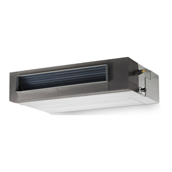
Indoor Units Part 2 Indoor Units Super Slim Cassette Type ........... 8 A5 Duct Type ..............23 A6 Duct Type ..............39 Ceiling & Floor Type ............57 Four-way Cassette Type (Compact) ......... 73 Console Type ..............83 Floor-standing Type ............96 Floor-standing Type ............ - Page 10 Super Slim Cassette Type Super Slim Cassette Type 1. Features ................9 2. Dimensions ..............12 3. Service Space ..............13 4. Wiring Diagrams ............14 5. Air Velocity Distributions (Reference Data) ....15 6. Electric Characteristics ..........18 7. Sound Levels ..............19 8.
-
Page 11: Features
Features 1. Features 1.1 Overview Compact design, super slim body size, less space requiring in installation Each louver can be separately controlled, more comfort air blowing is possible. Auto-lifting panel design, more convenient to clean and maintain the filter. (optional) Fresh air intake function ... - Page 12 Features Built-in draining pump Due to the improvement of structure, more convenient to repair or replace the draining pump. Draining Pump Built-in draining pump to make sure condensed water drain out reliably. 1.6 Terminals for alarm lamp and long-distance on-off controller connection are standard ...
- Page 13 Features Alarm lamp Long-distance on-off controller 1.7 Twins Combination(18k-30k) The units can be installed as Twin systems: one outdoor unit can connect with two indoor units. The indoor units can be combined in any of the different available ratings. Indoor Units...
-
Page 14: Dimensions
Dimensions 2. Dimensions 9 2 9 2 F re s h a ir in ta ke 1 3 6 4 -in s ta ll h a n g e r 1 2 6 6 8 0 B o d y G a s sid e L iq u id sid e W irin g c o n n e c tio n p o rt... -
Page 15: Service Space
Service Space 3. Service Space >1000m m >1000mm Chart 3 Indoor Units... -
Page 16: Wiring Diagrams
Wiring Diagrams 4. Wiring Diagrams Indoor Units... -
Page 17: Air Velocity Distributions (Reference Data)
Air Velocity Distributions (Reference Data) Air Velocity Distributions (Reference Data) 18-24K: Cooling: Heating: Indoor Units... - Page 18 Air Velocity Distributions (Reference Data) 30-42K: Cooling: Heating: Indoor Units...
- Page 19 Air Velocity Distributions (Reference Data) 48-55K: Cooling: Heating: Indoor Units...
-
Page 20: Electric Characteristics
Electric Characteristics Electric Characteristics Indoor Unit Power Supply Model Voltage V4MCI-24UR 220-240V 198V 254V V4MCI-36UR 220-240V 198V 254V V4MCI-42 220-240 198V 254V V4MCI-50UR 220-240V 198V 254V V4MCI-60UR 220-240V 198V 254V Notes: MFA: Max. Fuse Amps. (A) Indoor Units... -
Page 21: Sound Levels
Sound Levels Sound Levels 1. 4m M ic ro p h o n e Noise level dB(A) Model Noise Power dB(A) V4MCI-24UR V4MCI-36UR V4MCI-42 V4MCI-50UR V4MCI-60UR Indoor Units... -
Page 22: Accessories
Accessories Accessories Name Shape Quantity Installation Fittings Installation paper board Tubing & Fittings Soundproof / insulation sheath Out-let pipe sheath Out-let pipe clasp Drainpipe Fittings Drain joint Seal ring Remote controller & Its Frame Remote controller & Its Frame(The product you Remote controller holder have might not be provided the following... -
Page 23: The Specification Of Power
The Specification of Power 9. The Specification of Power Model(Btu/h) 18000~24000 30000 36000 36000 Phase 1-phase 1-phase 1-phase 3-phase Frequency 220-240V, 50Hz 220-240V, 50Hz 220-240V, 50Hz 380-415V, 50Hz POWER Voltage POWER WIRING 3×2.5 3×2.5 3×4.0 5×2.5 (mm2) CIRCUIT BREAKER/Fuse (A) 30/20 40/30 40/30... -
Page 24: Field Wiring
Field Wiring 10. Field Wiring Indoor Units... -
Page 25: A5 Duct Type
A5 Duct Type A5 Duct Type 1. Features ................. 24 2. Dimensions ..............27 3. Service Space ..............28 4. Wiring Diagrams ............29 5. Static Pressure ............... 31 6. Electric Characteristics ..........34 7. Sound Levels ..............35 8. Accessories ..............36 9. -
Page 26: Features
Features Features 1.1 Easy Installation: Two air inlet styles (Bottom side or Rear side) Air inlet from rear is standard for all capacity; air inlet from bottom is optional. The size of air inlet frame from rear and bottom is same, it’s very easy to move the cover from bottom to rear side, or from rear to the bottom, in order to matching the installation condition. - Page 27 Features Motor Blower Housing Ventilated Panel 1.4 Reserved remote on-off and central control ports Reserved remote on-off ports and central control ports, can connect the cable of an on-off controller or a central controller to realize remote on-off control function or group control function. Remote on-off ports Central control ports 1.5 Built-in drain pump (Optional):...
- Page 28 Features 1.6 Built-in display board The standard indoor unit can be controlled by wired controller. There is a display board with a receiver in the E-box. Move out the display, and fix it in other place, even in the distance of 2m. The unit will realized remoter control. ...
-
Page 29: Dimensions
Dimensions Dimensions a ir in le t fro m re a r sid e A ir filte r ( o p tio n a l ) 4 -in s ta ll h a n g e r L iq u id sid e 2 5 D ra in p ip e G a s sid e 2 5 D ra in p ip e... -
Page 30: Service Space
Service Space Service Space Ensure enough space required for installation and maintenance. All the indoor units reserve the hole to joint the fresh air pipe. The hole size as following: Indoor Units... -
Page 31: Wiring Diagrams
Wiring Diagrams Wiring Diagrams V4MDI-12 V4MDI-18UR Indoor Units... - Page 32 Wiring Diagrams V4MDI-24UR, V4MDI-36UR, V4MDI-42, V4MDI-50, V4MDI-60 Pre-setting Instructions Indoor Units...
-
Page 33: Static Pressure
Static Pressure Static Pressure V4MDI-12 V4MDI-18UR Indoor Units... - Page 34 Static Pressure V4MDI-24UR Indoor Units...
- Page 35 Static Pressure V4MDI-36UR V4MDI-42, V4MDI-50, V4MDI-60 Indoor Units...
-
Page 36: Electric Characteristics
Electric Characteristics Electric Characteristics Indoor Unit Power Supply Model Voltage Min. Max. V4MDI-12 220-240V 198V 254V V4MDI-18UR 220-240V 198V 254V V4MDI-24UR 220-240V 198V 254V V4MDI-36UR 198V 220-240V 254V V4MDI-42 220-240V 198V 254V V4MDI-50 220-240V 198V 254V V4MDI-60 220-240V 198V 254V Note: MFA: Max. -
Page 37: Sound Levels
Sound Levels Sound Levels C o n c e a le d D u c t T y p e D is c h a rg e S u c tio n D u c t D u c t 1 .4 m M ic ro p h o n e Noise level dB(A) -
Page 38: Accessories
Accessories 8. Accessories Name Shape Quantity Soundproof / insulation sheath Tubing & Fittings Binding tape Seal sponge Drain joint Drainpipe Fittings (for cooling & heating) Seal ring Wired controller & Its Frame Wired controller , Owner s manual Others Installation manual Magnetic ring (twist the electric wires L EMS &... -
Page 39: The Specification Of Power
The Specification of Power The Specification of Power Model(Btu/h) 12000 18000-24000 30000 36000 36000 Phase 1-phase 1-phase 1-phase 1-phase 3-phase Frequency and 220-240V, 220-240V, 220-240V, 220-240V, 380-415V, POWER Voltage 50Hz 50Hz 50Hz 50Hz 50Hz POWER 3×2.5 3×2.5 3×2.5 3×4.0 5×2.5 WIRING (mm CIRCUIT BREAKER/Fuse (A) 20/16... -
Page 40: Field Wiring
Field Wiring Field Wiring V4MDI-12 V4MDI-18UR, V4MDI-24UR, V4MDI-36UR, V4MDI-42, V4MDI-50, V4MDI-60 Indoor Units... -
Page 41: A6 Duct Type
A6 Duct Type A6 Duct Type 1. Features ................40 2. Dimensions ..............43 3. Service Space ..............44 4. Wiring Diagrams ............45 5. Static Pressure ............... 46 6. Electric Characteristics ..........52 7. Sound Levels ..............53 8. Accessories ..............54 9. -
Page 42: Features
Features Features 1.1 Higher Static Pressure As a ducted air conditioner with medium static pressure, it has the widest static pressure range. The maximum static pressure reaches 160 Pa 1.2 Slim Design The industry lowest height is designed to be fitted into tight roof spaces. *18K unit - 210mm,24K/36K unit - 249mm,48K unit -300mm Constant air volume control ... - Page 43 Features Air intake from bottom (Optional) Air intake from rear (Standard) 1.5 Communication wire connection A6 duct uses two wires without polarity connection way, which almost has no mistake during the Ø installation. 1.6 Easy Clean With a larger window design, once the motor and the blower wheels have been detached, heat Ø...
- Page 44 Features 1.8 Built-in drain pump (Optional) Built-in drain pump can lift the water to 750mm upmost, which widens the drainage piping range. Indoor Units...
-
Page 45: Dimensions
Dimensions Dimensions Model unit (KBtu/h) inch 27.6 19.9 17.7 21.1 23.6 29.2 14.2 inch 34.65 8.27 26.54 23.62 5.51 27.80 1.97 5.35 30.79 7.48 1.57 36.22 20.00 3.07 5.83 3.46 4.41 1100 1001 1140 inch 43.31 9.80 30.47 27.56 5.51 36.46 1.97 6.89... -
Page 46: Service Space
Service Space Service Space Ensure enough space required for installation and maintenance. Indoor Units... -
Page 47: Wiring Diagrams
Wiring Diagrams Wiring Diagrams 18k~55k Indoor Units... -
Page 48: Static Pressure
Static Pressure Static Pressure V4MDI-12 A ir flow rate(m 3/h ) ( no filter ) 1 2 0 0 1 1 0 0 PS : SP4 M = = SP3 H 1 0 0 0 9 0 0 8 0 0 7 0 0 6 0 0 5 0 0... - Page 49 Static Pressure V4MDI-18UR A ir flow rate ( m 3/h ) ( no filter ) 2 0 0 0 1 8 0 0 1 6 0 0 1 5 0 0 1 4 0 0 1 2 0 0 1 0 0 0 8 0 0 6 0 0 5 0 0...
- Page 50 Static Pressure V4MDI-24UR A ir flow rate(m 3/h ) ( no filter ) 2 4 0 0 2 2 0 0 2 0 0 0 1 8 0 0 1 6 0 0 1 4 0 0 1 2 0 0 1 0 0 0 8 0 0 6 0 0...
- Page 51 Static Pressure V4MDI-36UR A ir flow rate(m 3/h ) ( no filter ) 3 2 0 0 3 0 0 0 2 8 0 0 2 6 0 0 2 5 0 0 2 4 0 0 2 2 0 0 2 0 0 0 1 8 0 0 1 6 0 0...
- Page 52 Static Pressure V4MDI-42 A ir flow rate(m 3/h ) ( no filter ) 4 8 0 0 4 4 0 0 4 0 0 0 3 6 0 0 3 2 0 0 3 1 0 0 2 8 0 0 2 4 0 0 2 0 0 0 1 6 0 0...
- Page 53 Static Pressure V4MDI-50, V4MDI-60 A ir flow rate(m 3/h ) ( no filter ) 4 8 0 0 4 4 0 0 4 0 0 0 3 6 0 0 3 2 0 0 3 1 0 0 2 8 0 0 2 4 0 0 2 0 0 0 1 6 0 0...
-
Page 54: Electric Characteristics
Electric Characteristics 6. Electric Characteristics Indoor Unit Power Supply Model Voltage Min. Max. V4MDI-12 220-240V 198V 254V V4MDI-18UR 220-240V 198V 254V V4MDI-24UR 220-240V 198V 254V V4MDI-36UR 220-240V 198V 254V 220-240V 198V 254V V4MDI-42 220-240V 198V 254V V4MDI-50 220-240V 198V 254V V4MDI-60 Note: MFA: Max. -
Page 55: Sound Levels
Sound Levels Sound Levels C o n c e a le d D u c t T y p e D is c h a rg e S u c tio n D u c t D u c t 1 .4 m M ic ro p h o n e Noise level dB(A) -
Page 56: Accessories
Accessories 8. Accessories Name Shape Quantity Tubing & Fittings Soundproof / insulation sheath Drain joint Drainpipe Fittings (for cooling & heating) Seal ring Magnetic ring EMC & It’s Fitting (twist the electric wires L and N around (for some models) the magnetic ring to five circles) Wired controller Wired controller &... -
Page 57: The Specification Of Power
The Specification of Power The Specification of Power Model(Btu/h) 12000 18000-24000 30000 36000 36000 Phase 1-phase 1-phase 1-phase 1-phase 3-phase Frequency and 220-240V, 220-240V, 220-240V, 220-240V, 380-415V, POWER Voltage 50Hz 50Hz 50Hz 50Hz 50Hz POWER 3×2.5 3×2.5 3×2.5 3×4.0 5×2.5 WIRING (mm CIRCUIT BREAKER/Fuse (A) 20/16... -
Page 58: Field Wiring
Field Wiring Field Wiring 18K~55K Indoor Units... -
Page 59: Ceiling & Floor Type
Ceiling & Floor Type Ceiling & Floor Type 1. Features ....................58 2. Dimensions ..................59 3. Service Space ..................60 4. Wiring Diagrams ................61 5. Electric Characteristics ..............63 6. Sound Levels ..................64 7. Air Velocity and Temperature Distributions (Reference Data) ..65 8. -
Page 60: Features
Ceiling & Floor Type 1. Features 1.1. New design, more modern and elegant appearance. 1.2. Convenient installation --The ceiling type can be easily installed into a corner of the ceiling even if the ceiling is very narrow --It is especially useful when installation of an air conditioner in the center of the ceiling is impossible due to a structure such as one lighting. -
Page 61: Dimensions
Ceiling & Floor Type 2. Dimensions W irin g c o n n e c tio n p o rt D ra in d is c h a rg e p o rt 1 2 0 F re s h a ir in ta k e R e frig e ra n t p ip e h o le 1 2 0 H a n g in g a rm... -
Page 62: Service Space
Ceiling & Floor Type 3. Service Space Indoor Units... -
Page 63: Wiring Diagrams
Ceiling & Floor Type 4. Wiring Diagrams V4MKI-18 V4MKI-24UR V4MKI-36UR, V4MKI-50 Indoor Units... - Page 64 Ceiling & Floor Type V4MKI-36UR, V4MKI-50, V4MKI-60 Indoor Units...
-
Page 65: Electric Characteristics
Ceiling & Floor Type 5. Electric Characteristics Indoor Units Power Supply Model Voltage Min. Max. 220-240V 198V 254V V4MKI-18 220-240V 198V 254V V4MKI-24UR 220-240V 198V 254V V4MKI-36UR 220-240V 198V 254V V4MKI-48 220-240V 198V 254V V4MKI-50 V4MKI-60 220-240V 198V 254V Note MFA: Max. -
Page 66: Sound Levels
Ceiling & Floor Type 6. Sound Levels M ic ro p h o n e 1 . 5 m A ir o u tle t sid e M icro p h o n e Ceiling Floor Noise level dB(A) Sound Power Model dB (A) V4MKI-18... -
Page 67: Air Velocity And Temperature Distributions (Reference Data)
Ceiling & Floor Type 7. Air Velocity and Temperature Distributions (Reference Data) Model: 18k,24k Ceiling installation: Discharge angle 17° Discharge angle 50° Indoor Units... - Page 68 Ceiling & Floor Type Floor installation: Discharge angle 17° Discharge angle 50° Indoor Units...
- Page 69 Ceiling & Floor Type Model: 36k Ceiling installation: Discharge angle 17° Discharge angle 50° Indoor Units...
- Page 70 Ceiling & Floor Type Floor installation: Discharge angle 17° Discharge angle 50° Indoor Units...
- Page 71 Ceiling & Floor Type Model: 42k,48k,55k Ceiling installation: Discharge angle 17° Discharge angle 50° Indoor Units...
- Page 72 Ceiling & Floor Type Floor installation: Discharge angle 17° Discharge angle 50° Indoor Units...
-
Page 73: Accessories
Ceiling & Floor Type 8. Accessories Name Shape Quantity 1. Remote controller Remote controller & Its holder(The product you 2. Remote controller holder have might not be provided the following accessories) 3. Mounting screw (ST2.9×10-C-H) 4. Alkaline dry batteries (AM4) 5. -
Page 74: Field Wiring
Field Wiring 10. Field Wiring Indoor Units... -
Page 75: Four-Way Cassette Type (Compact)
Four-way Cassette Type (Compact) Four-way Cassette Type (Compact) 1. Features ....................74 2. Dimensions ..................76 3. Service Space ..................77 4. Wiring Diagrams .................. 78 5. Air Velocity and Temperature Distributions (Reference Data) ..79 6. Electric Characteristics ..............80 7. -
Page 76: Features
Features 1. Features 1.1 New panel 360°surrounding air outlet design, affords comfortable feeling Ø 1.2 Compact design The body size is 570×260×570mm, it’s just smaller than the ceiling board, so it’s very easy for Ø installation and will not damage the decoration. The panel size is 647×50×647mm. Ø... - Page 77 Features Indoor Units...
-
Page 78: Dimensions
Dimensions 2. Dimensions V4MCRI-12,V4MCRI-18 L iq u id sid e G a s sid e B o d y D ra in h o le W irin g co n n e c tio n p o rt ( fo r S e rvic e ) E -p a rts b o x 1 5 0 D istrib u tio n d u ct 1 7 0... -
Page 79: Service Space
Service Space 3. Service Space Indoor Units... -
Page 80: Wiring Diagrams
Wiring Diagrams 4. Wiring Diagrams V4MCRI-12 V4MCRI-18 Indoor Units... -
Page 81: Air Velocity And Temperature Distributions (Reference Data)
Air Velocity and Temperature Distributions (Reference Data) 5. Air Velocity and Temperature Distribution s (Reference Data) A irflow velocity T em perature Indoor Units... -
Page 82: Electric Characteristics
Electric Characteristics 6. Electric Characteristics Indoor Units Power Supply Model Voltage Min. Max. V4MCRI-12 220-240V 198V 254V V4MCRI-18 220-240V 198V 254V Note: MFA: Max. Fuse Amps. (A) 7. Sound Levels 1. 4m M ic ro p h o n e Noise level dB(A) Model Noise Power dB(A) -
Page 83: Accessories
Accessories 8. Accessories Name Shape Quantity Installation Fittings Installation paper board Tubing & Fittings Soundproof / insulation sheath Out-let pipe sheath Out-let pipe clasp Drainpipe Fittings Drain joint Seal ring Remote controller & Its Frame Remote controller & Its Frame(The product you Remote controller holder have might not be provided the following... -
Page 84: Field Wiring
Field Wiring 10. Field Wiring V4MCRI-12 V4MCRI-18 Indoor Units... -
Page 85: Console Type
Console Type Console Type 1. Features ....................85 2. Dimensions ..................88 3. Service Space ..................89 4. Wiring Diagrams .................. 90 5. Air Velocity and Temperature Distributions (Reference Data) ..91 6. Electric Characteristics ..............92 7. Sound Levels ..................93 8. -
Page 87: Features
Features 1. Features 1.1. Modern and elegant appearance The simple and stylish designs can nicely harmonies with your living space. Ø 1.2. Four panels optional 1.3. Two air-outlet ways Cooling mode Quick Cooling To maintain room temp Air outlet from top and bottom to make quick cooling ------When the A/C is just switched on, or room Ø... - Page 88 Features Anti-cold air ------When the AC is just turn on, temperature of evaporator is very low, in this case, in Ø order to prevent cold air direct blowing, only the upper louver is opened in a high position, the lower louver closed.
- Page 89 Features 1.7. Active carbon filter is standard. Console Type...
-
Page 90: Dimensions
Console Type 2. Dimensions 7 0 0 2 1 0 H a n g in g a rm 1 9 5 D r a i n p i p e U n it: m m Console Type... -
Page 91: Service Space
Console Type 3. Service Space Console Type... -
Page 92: Wiring Diagrams
Console Type 4. Wiring Diagrams V4MLI-12, V4MLI-18 Console Type... -
Page 93: Air Velocity And Temperature Distributions (Reference Data)
Console Type 5. Air Velocity and Temperature Distributions (Reference Data) Discharge angle 60 A irflow v elocity T em p erature Console Type... -
Page 94: Electric Characteristics
Console Type 6. Electric Characteristics Indoor Units Power Supply Model Voltage Min. Max. V4MLI-12 220-240V 198V 254V V4MLI-18 220-240V 198V 254V Console Type... -
Page 95: Sound Levels
Console Type 7. Sound Levels M icro p h o n e 1 .5 m Noise level dB(A) Noise Power Model dB(A) V4MLI-12 V4MLI-18 Console Type... -
Page 96: Accessories
Console Type 8. Accessories Name Shape Quantity Installation fittings Hook Remote controller Frame Remote controller & Its Frame Mounting screw(ST2.9×10-C-H) Alkaline dry batteries (AM4) Installation manual Others Owner's manual 9. The Specification of Power Model(Btu/h) 12000 16000 Phase 1-phase 1-phase POWER Frequency and Voltage 220-240V, 50Hz... -
Page 97: Field Wiring
Console Type 10. Field Wiring Console Type... -
Page 98: Floor-Standing Type
M Floor-standing Type Floor-standing Type 1.Features ................97 2. Dimensions ..............98 3. Service Space ..............99 4. Wiring Diagrams ............100 5. Electric Characteristics ..........102 6. Sound Levels ..............103 7. Accessories ..............104 8. The Specification of Power ......... 105 9. -
Page 99: Features
Features 1. Features 1.1 Fashionable design, concise and easy design better suits decoration style. 1.2. Dustproof Air Outlet When press OFF to turn off the unit, the air outlet louver can be closed automatically to prevent the dust falling in. 1.3. -
Page 100: Dimensions
Dimensions 2. Dimensions Dimension W(mm) D(mm) H(mm) Model V4MFI-24 1700 V4MFI-50 1934 V4MFI-66 1934 Floor-standing Type... -
Page 101: Service Space
Service Space 3. Service Space Floor-standing Type... -
Page 102: Wiring Diagrams
Wiring Diagrams 4. Wiring Diagrams V4MFI-24 V4MFI-50 Floor-standing Type... - Page 103 Wiring Diagrams V4MFI-66 Floor-standing Type...
-
Page 104: Electric Characteristics
Electric Characteristics 5. Electric Characteristics Indoor Units Power Supply Model Voltage Min. Max. V4MFI-24 220-240V 198V 254V V4MFO-50 220-240V 198V 254V V4MFI-66 380-415V 342V 440V Note: MFA: Max. Fuse Amps. (A) Floor-standing Type... -
Page 105: Sound Levels
Sound Levels 6. Sound Levels M ic ro p h o n e Noise level dB(A) Sound Power Model Level dB(A) V4MFI-24 V4MFI-50 V4MFI-66 Floor-standing Type... -
Page 106: Accessories
Accessories 7. Accessories Part Name Shape Quantity Safety Lock Self-tapping Screw 3.9×25 Flat Washers Bushing-Sleeve Cover Sound/Heat Insulation Sleeves Seal Drain joint Pipe - hole - protection Ring Remote Battery Remote Controller Remote controller manual User's manual Installation manual Remote controller holder(Optional parts) Ratproof board(on some models) Band(on some models) Drain Hose(on some models) -
Page 107: The Specification Of Power
The Specification of Power 8. The Specification of Power Model(Btu/h) 24000 Phase 1-phase POWER Frequency and Voltage 220-240V, 50Hz POWER WIRING (mm 3×2.5 CIRCUIT BREAKER/Fuse (A) 30/20 Indoor/Outdoor Connecting Wiring(Weak Electric Signal) (mm 2×0.2 Indoor/Outdoor Connecting Wiring(Strong Electric Signal)(mm 3×1.0 Model(KBtu/h) Phase 1-phase... -
Page 108: Field Wiring
Field Wiring 9. Field Wiring V4MFI-24 V4MFI-50 Floor-standing Type... - Page 109 Field Wiring V4MFI-66 Floor-standing Type...
-
Page 110: Floor-Standing Type
GA Floor-standing Type Floor-standing Type 1. Features ....................109 2. Dimensions ..................110 3. Service Space..................111 4. Wiring Diagrams ................112 5. Air Velocity and Temperature Distributions (Reference Data) ..113 6. Electric Characteristics ..............114 7. Sound Levels..................115 8. -
Page 111: Features
Features Features 1.1. Fashionable design, more modern and elegant appearance. 1.2. Air Outlet Dustproof When turned off, the air outlet louver of the unit can be closed manually to prevent the dust falling in. 1.3. Simple and bright panel Adopts simple and bright style panel, GA series are suitable for most different space, and show in good taste. -
Page 112: Dimensions
Dimensions Dimensions Dimension W(mm) D(mm) H(mm) Mode V4MFI-66B 1925 Floor-standing Type... -
Page 113: Service Space
Service Space Service Space Floor-standing Type... -
Page 114: Wiring Diagrams
Wiring Diagrams Wiring Diagrams V4MFI-66B Floor-standing Type... -
Page 115: Air Velocity And Temperature Distributions (Reference Data)
Air Velocity and Temperature Distributions (Reference Data) 5. Air Velocity and Temperature Distributions (Reference Data) Model 55K: A irflo w v elo city T em p eratu re Floor-standing Type... -
Page 116: Electric Characteristics
Electric Characteristics 6. Electric Characteristics Indoor Units Power Supply Model Voltage Min. Max. V4MFI-66B 380-415V 342V 440V Note: MFA: Max. Fuse Amps. (A) Floor-standing Type... -
Page 117: Sound Levels
Sound Levels Sound Levels M ic ro p h o n e Noise level dB(A) Sound Power Model Level dB(A) V4MFI-66B Floor-standing Type... -
Page 118: Accessories
Accessories Accessories Part Name Shape Quantity Safety Lock Self-tapping Screw 3.9×25 Flat Washers Bushing-Sleeve Cover Sound/Heat Insulation Sleeves Seal Drain joint Pipe - hole - protection Ring Remote Battery Remote Controller Connection Cables Remote controller manual User's manual Installation manual Floor-standing Type... -
Page 119: The Specification Of Power
The Specification of Power 9. The Specification of Power Model V4MFI-66B Phase 3-phase POWER Frequency and Voltage 380-415V, 50Hz POWER WIRING (mm 5×2.5 CIRCUIT BREAKER/Fuse (A) 32/25 Indoor/Outdoor Connecting Wiring(Weak Electric Signal) (mm 2×0.2 Indoor/Outdoor Connecting Wiring(Strong Electric Signal)(mm Floor-standing Type... -
Page 120: Field Wiring
Field Wiring Field Wiring Floor-standing Type... - Page 121 Outdoor Units Part 3 Outdoor Units 1. Dimensions ..............120 2. Service Space ............... 122 3. Wiring Diagrams ............123 4. Piping Diagrams ............128 5. Electric Characteristics ..........129 6. Operation Limits ............130 7. Sound Levels ..............131 Outdoor Units...
-
Page 122: Dimensions
Dimensions 1. Dimensions Unit:mm Model(KBtu/h) 12/16/18 30/36/42 1030 Outdoor Units... - Page 123 Dimensions Unit:mm Model(KBtu/h) 48/55 1333 1045 Outdoor Units...
-
Page 124: Service Space
Service Space 2. Service Space (Wall or obstacle) More than 30cm Air inlet More than 60cm More than 30cm Maintain channel Air inlet More than 60cm Air outlet More than 200cm Outdoor Units... -
Page 125: Wiring Diagrams
Wiring Diagrams 3. Wiring Diagrams V4MLO-12, U4MRS-12 Outdoor Units... - Page 126 Wiring Diagrams U4MRS-18 U4MRS-24 Outdoor Units...
- Page 127 Wiring Diagrams U4MRS-36 Outdoor Units...
- Page 128 Wiring Diagrams U4MRT-42 Outdoor Units...
- Page 129 Wiring Diagrams U4MRT-50 U4MRT-50, U4MRT-60 Outdoor Units...
-
Page 130: Piping Diagrams
Piping Diagrams 4. Piping Diagrams U4MRS-12, U4MRS-18, U4MRS-24 IN D O O R O U T D O O R E le ctro nic C A P IL IA R Y T U B E e xp an sion v alve... -
Page 131: Electric Characteristics
Electric Characteristics 5. Electric Characteristics Power Supply Outdoor Unit Model Voltage Min. Max. U4MRS-12 220-240V 198V 254V U4MRS-18 220-240V 198V 254V U4MRS-24 220-240V 198V 254V U4MRS-36 220-240V 198V 254V U4MRT-42 380-415V 342V 440V U4MRT-50 380-415V 342V 440V U4MRT-60 380-415V 342V... -
Page 132: Operation Limits
Operation Limits 6. Operation Limits Temperature Cooling operation Heating operation Drying operation Mode Room temperature 17℃~32℃ 0℃~30℃ 17℃~32℃ 0℃~50℃ (-15℃~50℃:For Outdoor temperature -15℃~24℃ 0℃~50℃ the models with low temperature cooling system) CAUTION: 1. If the air conditioner is used beyond the above conditions, certain safety protection features may come into operation and cause the unit to operate abnormally. -
Page 133: Sound Levels
Sound Levels 7. Sound Levels Outdoor Unit Microphone 1.0m Note: H= 0.5 × height of outdoor unit Model Noise Power dB(A) Noise level dB(A) U4MRS-12 U4MRS-18 U4MRS-24 U4MRS-36 U4MRT-42 U4MRT-50 U4MRT-60 Outdoor Units... -
Page 134: Part 4 Installation
Installation Part 4 Installation 1. Installation Procedure ..........133 2. Location selection ............134 3. Indoor unit installation ..........135 4. Outdoor unit installation (Side Discharge Unit) ..156 5. Refrigerant pipe installation ........157 6. Drainage pipe installation ..........161 7. -
Page 135: Installation Procedure
Installation Procedure 1. Installation Procedure Indoor unit installation Outdoor unit installation location selection location selection Indoor unit installation Outdoor unit installation Refrigerant pipe Refrigerant pipe installation and insulation installation and insulation Drainage pipe installation Drainage pipe installation and insulation and insulation Vacuum drying and leakage checking Additional refrigerant charge Insulation the joint part of refrigerant pipe... -
Page 136: Location Selection
Location selection 2. Location selection 2.1 Indoor unit location selection The place shall easily support the indoor unit’s weight. The place can ensure the indoor unit installation and inspection. The place can ensure the indoor unit horizontally installed. ... -
Page 137: Indoor Unit Installation
Indoor unit installation 3. Indoor unit installation 3.1 Super slim cassette indoor unit installation 3.1.1 Service space for indoor unit Model >235 24~42 >275 48/55 >317 3.1.2 Bolt pitch 3.1.3 Install the pendant bolt Select the position of installation hooks according to the hook holes positions showed in upper picture. Drill four holes of Ø12mm, 45~50mm deep at the selected positions on the ceiling. - Page 138 Indoor unit installation 3.1.4 Install the main body Make the 4 suspender through the 4 hanger of the main body to suspend it. Adjust the hexangular nuts on the four installation hooks evenly, to ensure the balance of the body. Use a leveling instrument to make sure the levelness of the main body is within ±1°.
- Page 139 Indoor unit installation Remove the 4 corner covers. Hang the panel to the hooks on the mainbody. If the panel is with auto-lift grille, please watch the ropes lifing the grille, DO NOT make the ropes enwinded or blocked. Tighten the screws under the panel hooks till the panel closely stick on the ceiling to avoid condensate water.
- Page 140 Indoor unit installation Hang the air-in grill to the panel, then connect the lead terminator of the swing motor and that of the control box with corresponding terminators on the body respectively. Install the 4 corner covers back. Note: The panel shall be installed after the wiring connected. Installation...
- Page 141 Indoor unit installation 3.2 A5 duct indoor unit installation 3.2.1 Service space for indoor unit 3.2.2 Bolt pitch Size of outline dimension mounted lug Capacity(KBtu) 18/24 1180 36~60 1240 3.2.3 Install the pendant bolt Select the position of installation hooks according to the hook holes positions showed in upper picture. Drill four holes of Ø12mm, 45~50mm deep at the selected positions on the ceiling.
- Page 142 Indoor unit installation 3.2.4 Install the main body Make the 4 suspender through the 4 hanger of the main body to suspend it. Adjust the hexangular nuts on the four installation hooks evenly, to ensure the balance of the body. Use a leveling instrument to make sure the levelness of the main body is within ±1°.
- Page 143 Indoor unit installation 3.2.7 Change the air inlet direction ① Take off ventilation panel and flange, cut off the staples at side rail. ② Stick the attached seal sponge as per the indicating place in the following fig, and then change the mounting positions of air return panel and air return flange .
- Page 144 Indoor unit installation 3.3 Ceiling & floor indoor unit installation 3.3.1 Service space for indoor unit 3.3.2 Bolt pitch ① Ceiling installation Capacity (KBtu/h) 18/24 1200 36~60 1565 ② Wall-mounted installation 3.3.3 Install the pendant bolt ① Ceiling installation Installation...
- Page 145 Indoor unit installation Select the position of installation hooks according to the hook holes positions showed in upper picture. Drill four holes of Ø12mm, 45~50mm deep at the selected positions on the ceiling. Then embed the expansible hooks (fittings). ② Wall-mounted installation Install the tapping screws onto the wall.(Refer to picture below) 3.3.4 Install the main body ①...
- Page 146 Indoor unit installation Put the side panels and grilles back. ② Wall-mounted installation Hang the indoor unit by insert the tapping screws into the hanging arms on the main unit. (The bottom of body can touch with floor or suspended, but the body must install vertically.) Installation...
- Page 147 Indoor unit installation 3.4 Compact cassette indoor unit installation 3.4.1 Service space for indoor unit 3.4.2 Bolt pitch 3.4.3 Install the pendant bolt Select the position of installation hooks according to the hook holes positions showed in upper picture. Drill four holes of Ø12mm, 45~50mm deep at the selected positions on the ceiling. Then embed the expansible hooks (fittings).
- Page 148 Indoor unit installation If the ceiling is extremely high, please determine the length of the installation hook depending on the real situation. 3.4.4 Install the main body Make the 4 suspender through the 4 hanger of the main body to suspend it. Adjust the hexangular nuts on the four installation hooks evenly, to ensure the balance of the body.
- Page 149 Indoor unit installation Hang the panel to the hooks on the mainbody. Tighten the screws under the panel hooks till the panel closely stick on the ceiling to avoid condensate water. Hang the air-in grill to the panel, then connect the lead terminator of the swing motor and that of the control box with corresponding terminators on the body respectively.
- Page 150 Indoor unit installation 3.5 Console indoor unit installation 3.7.7 Service space for indoor unit 3.7.8 Install the main body Fix the hook with tapping screw onto the wall Hang the indoor unit on the hook. (The bottom of body can touch with floor or suspended, but the body must install vertically.) Installation...
- Page 151 Indoor unit installation 3.6 GA floor standing indoor unit installation 3.6.1 Service space for indoor unit a. A place which provides the spaces around the indoor unit as required above in the diagram. b. A place where is no obstacle near the inlet and outlet area. c.
- Page 152 Indoor unit installation 3.6.2.2. Dismounting the lower front panel Please take off the air-inlet grid before connecting the pipes/wires. Pull down the two knobs on the grille, take off the two screws, then the air-inlet grille goes free. 3.6.2.3. Take the Pipe Clip off before connecting the pipes and wiring; fit it when these finished. Use accessories to connect the pipes/wires on both sides and back side.
- Page 153 Indoor unit installation 3.7 M floor standing indoor unit installation 3.7.1 Service space for indoor unit a. A place which provides the spaces around the indoor unit as required above in the diagram. b. A place where is no obstacle near the inlet and outlet area. c.
- Page 154 Indoor unit installation Please take off the air-inlet grid before connecting the pipes/wires. The grid is hitched by a loop inside. To dismount the air-inlet grid, hold both sides of the grid and pull it up, let it slant downwards until the loop become straight. Then removing the screws fastened the loop with the grid, and the grid goes free.
- Page 155 Indoor unit installation 3.8 A6 duct indoor unit installation 3.8.1. Service space for indoor unit 3.8.2. Bolt pitch Size of outline dimension mounted lug Capacity(KBtu) 1140 1400 3.8.3. Hang indoor unit 1. Please refer to the upper data to locate the four positioning screw bolt hole on the ceiling. Be sure to mark the areas where ceiling hook holes will be drilled.
- Page 156 Indoor unit installation 5. Drill 4 holes 10cm (4”) deep at the ceiling hook positions in the internal ceiling. Be sure to hold the drill at a 90° angle to the ceiling. 6. Secure the bolt using the washers and nuts provided. 7.
- Page 157 Indoor unit installation NOTE: 1.Do not put the connecting duct weight on the indoor unit. 2.When connecting duct, use inflammable canvas tie-in to prevent vibrating. 3. Insulation foam must be wrapped outside the duct to avoid condensate. An internal duct underlayer can be added to reduce noise, if the end-user requires.
-
Page 158: Outdoor Unit Installation (Side Discharge Unit)
Outdoor unit installation (Side Discharge Unit) 4. Outdoor unit installation (Side Discharge Unit) 4.1 Service space for outdoor unit (Wall or obstacle) More than 30cm Air inlet More than 60cm More than 30cm Maintain channel Air inlet More than 60cm Air outlet More than 200cm 4.2 Bolt pitch... -
Page 159: Refrigerant Pipe Installation
Refrigerant pipe installation 5. Refrigerant pipe installation 5.1 Maximum pipe length and height drop Considering the allowable pipe length and height drop to decide the installation position. Make sure the distance and height drop between indoor and outdoor unit not exceeded the date in the following table. Model Max. - Page 160 Refrigerant pipe installation Flare dimension A (mm) Pipe diameter Flare shape 9 0 ° 4 1/4" (6.35) 3/8" (9.52) 12.0 12.4 R 0 .4 ~ 0 .8 1/2" (12.7) 15.4 15.8 5/8" (15.9) 18.6 19.1 3/4" (19) 22.9 23.3 After flared the pipe, the opening part must be seal by end cover or adhesive tape to avoid duct or exogenous impurity come into the pipe.
- Page 161 Refrigerant pipe installation Note: All used branch pipe must be produced by Inventor, otherwise it causes malfunction. The indoor units should be installed equivalently at the both side of the U type branch pipe. Permitted Value Piping 18K+18K Total pipe length (Actual)
- Page 162 Refrigerant pipe installation Installation...
-
Page 163: Drainage Pipe Installation
Drainage pipe installation 6. Drainage pipe installation Install the drainage pipe as shown below and take measures against condensation. Improperly installation could lead to leakage and eventually wet furniture and belongings. 6.1 Installation principle Ensure at least 1/100 slope of the drainage pipe ... - Page 164 Drainage pipe installation 6.2.3 Individual design of drainage pipe system The drainage pipe of air conditioner shall be installed separately with other sewage pipe, rainwater pipe and drainage pipe in building. The drainage pipe of the indoor unit with water pump should be apart from the one without water pump. 6.2.4 Supporter gap of drainage pipe ...
- Page 165 Drainage pipe installation In d o o r u n it M o re th a n 5 0 m m P lu g M o re th a n 2 5 m m W a te r s to ra g e p ip e 6.2.7 Lifting pipe setting of indoor unit with water pump ...
- Page 166 Drainage pipe installation 6.3 Drainage test 6.3.1 Water leakage test After finishing the construction of drainage pipe system, fill the pipe with water and keep it for 24 hours to check whether there is leakage at joint section. 6.3.2 Water discharge test Natural drainage mode(the indoor unit with outdoor drainage pump) Infuse above 600ml water through water test hole slowly into the water collector, observe whether the water can discharge through the transparent hard pipe at drainage outlet.
-
Page 167: Vacuum Drying And Leakage Checking
Vacuum Drying and Leakage Checking 7. Vacuum Drying and Leakage Checking 4.1 Purpose of vacuum drying Eliminating moisture in system to prevent the phenomena of ice-blockage and copper oxidation. Ice-blockage shall cause abnormal operation of system, while copper oxide shall damage compressor. ... -
Page 168: Additional Refrigerant Charge
Additional refrigerant charge 8. Additional refrigerant charge After the vacuum drying process is carried out, the additional refrigerant charge process need to be performed. The outdoor unit is factory charged with refrigerant. The additional refrigerant charge volume is decided by the diameter and length of the liquid pipe between indoor and outdoor unit. -
Page 169: Engineering Of Insulation
Engineering of insulation 9. Engineering of insulation 9.1 Insulation of refrigerant pipe 9.1.1 Operational procedure of refrigerant pipe insulation Cut the suitable pipe → insulation (except joint section) → flare the pipe → piping layout and connection→ vacuum drying → insulate the joint parts 9.1.2 Purpose of refrigerant pipe insulation ... - Page 170 Engineering of insulation Installation...
-
Page 171: Engineering Of Electrical Wiring
Engineering of electrical wiring 9.2.3 Insulation material selection for drainage pipe The insulation material should be flame retardant material, the flame retardancy of the material should be selected according to the local law. Thickness of insulation layer is usually above 10mm. ... -
Page 172: Test Operation
Test operation 11. Test operation 11.1 The test operation must be carried out after the entire installation has been completed. 11.2 Please confirm the following points before the test operation. The indoor unit and outdoor unit are installed properly. ... -
Page 173: Part 5 Electrical Control System
Electrical Control System Part 5 Electrical Control System 1. Electrical Control Function ........172 2. Troubleshooting ............184 3. Controller ..............222 Electrical Control System... - Page 174 Electrical Control Function 1. Electrical Control Function 1.1 Abbreviation T1: Indoor room temperature T2: Middle indoor heat exchanger coil temperature T2B: Indoor heat exchanger exhaust coil temperature T3: Outdoor heat exchanger pipe temperature T4: Outdoor ambient temperature T5: Compressor discharge temperature 1.2 Main Protection 1.2.1 Compressor three-minute delay at restart Compressor functions are delayed for up to one minute upon the first startup of the unit, and are delayed for...
- Page 175 Electrical Control Function 0: No malfunction 1:P0 Overcurrent 2:Overpressure 3:Overload 4:Over speed 5:Startup malfunction 6:Lack of phase 7:DC voltage too low 8:Communication fault 9:Parameter fault 10:L3 Current limited 11:L5 Voltage limited 12: Target speed cannot be met during the static pressure calculation process. For other models: If the indoor fan speed is lower than 300 RPM for 50 seconds or more, it shuts off and restarts in 30 seconds.
- Page 176 Electrical Control Function 1.3 Operation Modes and Functions 1.3.1 Fan Mode (1) Outdoor fan and compressor cease operation. (2) Temperature setting function is disabled, and no preset temperature is displayed. (3) Louver operates the same as in cooling mode. (4) Auto fan: When it fan-only mode, operates the same as auto fan in cooling mode with the temperature set at 24℃.
- Page 177 Electrical Control Function 16~60K 1.3.2.3 Indoor Fan Running Guidelines In cooling mode, the indoor fan runs continuously and You can select the following speeds: high, medium, low, auto or silent. When the compressor is running, The indoor fan is regulated as illustrated as in the following figure: Setting fan T1-Td ℃(°...
- Page 178 Electrical Control Function T 1 -T d (H -L )*0 .7 5 + L (H -L )*0 .5 + L (H -L )*0 .2 5 + L 1.3.2.3 Evaporator Low Temperature T2 Protection. ---T2<0℃, the compressor stops and restarts only when T2≥5℃. ---0℃≤T2<4℃, the compressor frequency is limited and decreases to a lower level ---4℃≤T2<7℃, the compressor maintains its current frequency.
- Page 179 Electrical Control Function 16~60K: 1.3.3.2 Indoor Fan Running Guidelines In heating mode, indoor fan speed can be set at high, medium, low, or auto fan, and the anti-cold-wind function is preferential. When the compressor is running, The indoor fan is regulated as illustrated as in the following figure: Setting fan T1-Td℃...
- Page 180 Electrical Control Function T 1 -T d (H + -L )*0 .2 + L (H + -L )*0 .4 + L (H + -L )*0 .6 + L (H + -L )*0 .6 + L (H + -L )*0 .8 + L 1.3.3.3 Defrosting Control:...
- Page 181 Electrical Control Function The indoor fan runs at auto fan in each mode. The louver operates the same in each mode. If the machine switches mode between heating and cooling, the compressor stops for 15 minutes and then selects a mode again according to T1-Ts. If the temperature is modified, the machine selects a running function.
- Page 182 Electrical Control Function The system checks the water level every 5 seconds. ----When the A/C operates in cooling (including auto cooling) or forced cooling mode, the pump begins running immediately and continuously until cooling stops. ----If the water level increases up to the control point, the LED displays an alarm code and the drain pump opens and continually monitors the water level.
- Page 183 Electrical Control Function If the value is higher than 99, the digital display shows single and double digits. For example, if the digital display shows “2.0", the EXV open angle is 120×4=480p. Frequency limit Bit7 caused by IGBT radiator Frequency limit Bit6 caused by PFC The display value is a...
- Page 184 Electrical Control Function If the indoor unit is not connected, the digital display shows: “――” If the temperature is lower than 0 ℃, the digital display shows “0”. Average of indoor room temperature If the temperature is higher than 70 ℃, the digital display shows “70”.
- Page 185 Electrical Control Function Compressor overcurrent protection Compressor EE malfunction Compressor start-up malfunction 311 fan speed has been malfunction Low pressure protection High pressure protection PFC module malfunction Shutdown stop Electrical disconnect DR stop Electrical Control System...
- Page 186 Troubleshooting 2. Troubleshooting 2.1 Display board 2.1.1 Icon explanation on indoor display board (Super slim cassette). 2.1.2 Icon explanation on indoor display board (A5&A6 Duct) PRE-DEF indicator(cooling and heating type) or fan only indicator(cooling only type) Alarm indicator Timer indicator Infrared signal receiver Operation lamp Display digital tube...
- Page 187 Troubleshooting 2.1.5 Icon explanation on indoor display board (Compact cassette). 2.1.6 Icon explanation on indoor display board (Console) 2.1.7 Display board of floor-standing Electrical Control System...
- Page 188 Troubleshooting 2.1.8 Display board of floor-standing Electrical Control System...
- Page 189 Troubleshooting 2.2 Indoor Unit Malfunctions For the Console Operation Lamp Malfunction Timer Lamp (flashes) Indoor EEPROM malfunction Communication malfunction between indoor and outdoor units Indoor fan speed malfunction T1 temperature sensor open or short circuit T2 temperature sensor open or short circuit Refrigerant leakage Overcurrent protection (for some units) T4 temperature sensor open or short circuit...
- Page 190 Troubleshooting Floor Standing Malfunction Error Code Indoor EEPROM malfunction Communication malfunction between indoor and outdoor units Indoor fan speed malfunction T1 temperature sensor open or short circuit T2 temperature sensor open or short circuit Refrigerant leakage detection Outdoor unit is faulty (for old communication protocol) Overcurrent protection (for some units) T4 temperature sensor open or short circuit T3 temperature sensor open or short circuit...
- Page 191 Troubleshooting ☆ Inverter compressor drive protection ☆ Compressor low pressure protection ☆ Outdoor IGBT sensor is faulty X(off) ☆(flash at 2Hz) O (on) 2.3 Outdoor Unit Malfunctions For 16K: Contents LED1(Green) LED2(Red) Normal standby Normal operation DC voltage too high/too low protection or MCE malfunction Compressor driven chip EEPROM malfunction Flash Compressor speed malfunction...
- Page 192 Troubleshooting 2.4 Resolving Typical Malfunctions 2.4.1 For Indoor Units 2.4.1.1 Temperature Sensor Open or Short Circuit Malfunction conditions If the sampling voltage is lower than 0.06V or higher than 4.94V, the LED will display the failure. Possible causes ● Wiring mistakes ●...
- Page 193 Troubleshooting 2.4.1.3. Indoor EEPROM Malfunction Malfunction conditions Main PCB chip does not receive feedback from EEPROM chip Possible causes ● Installation mistakes ● Faulty PCB Power off, then restart the unit 2 minutes later. Does a problem remain? Replace the indoor main PCB EEPROM: An electrically erasable programmable read-only memory whose contents can be erased and reprogrammed using a pulsed voltage.
- Page 194 Troubleshooting 2.4.1.5. Indoor Fan Speed Malfunction Malfunction conditions When indoor fan speed continues to run at too low a speed (300RPM) for a certain period of time, the unit will stop and the LED will display a failure code. Possible causes ●...
- Page 195 Troubleshooting DC motor voltage input and output Color Signal Voltage Vs/Vm 200V~380V Black White 13.5-16.5V Yellow 0~6.5V Blue 13.5-16.5V Electrical Control System...
- Page 196 Troubleshooting 2.4.1.6. Refrigerant Leakage Detection Malfunction conditions Define the evaporator coil temperature T2 of the compressor starts running as Tcool. If the following occurs 3 times, the display shows "EC" and the unit switches off: In the first 8 minutes after the compressor starts up, if T2 <Tcool-2℃ is not maintained for 4 seconds and compressor running frequency is not higher than 50Hz for 3 minutes Potential causes...
- Page 197 Troubleshooting 2.4.1.7 Outdoor IGBT sensor is faulty Check the connection between temperature Ensure proper connection sensor and PCB. Is it properly wired? Measure the resistance value of the sensor. Is it Replace the sensor within acceptable parameters? Replace outdoor main PCB 2.4.1.8 Communication malfunction between indoor and outdoor units The same as E1 in outdoor.
- Page 198 Troubleshooting 2.4.2 Super-Slim Cassettes with an Up-Down Panel 2.4.2.1 Communication Errors between Indoor Unit and Up-Down Panel F0 Displayed F0 Displayed Communication failure between Communication failure between indoor unit and up-down panel indoor unit and up-down panel Check the wire connection Check the wire connection between up-down panel and between up-down panel and...
- Page 199 Troubleshooting 2.4.3 Units with TWINS Function (for the Super-Slim Cassette & A5 Duct) 2.4.3.1 Communication between Master Unit and Indoor Unit Malfunction F3 Displayed F3 Displayed Communication failure between Communication failure between master unit and slave unit master unit and slave unit Check the dial switch settings of Check the dial switch settings of Correct the...
- Page 200 Troubleshooting 2.4.4 Outdoor Units 2.4.4.1. Compressor Driven Chip EEPROM Malfunction Malfunction conditions Main PCB chip does not receive feedback from EEPROM chip Possible causes ● Installation mistakes ● Faulty PCB Compressor driven chip Compressor driven chip EEPROM malfunction EEPROM malfunction Power off, then restart the Power off, then restart the unit 2 minutes later.
- Page 201 Troubleshooting 2.4.4.2 Compressor Speed Malfunction/ Zero Speed Protection / Synchronous Fault Protection LED1(Green) off/LED2(Red) flash LED1(Green) off/LED2(Red) flash or LED1(Green) flash/LED2(Red) on or LED1(Green) flash/LED2(Red) on Is there at least one LED in Is there at least one LED in the compressor driven chip the compressor driven chip light?
- Page 202 Troubleshooting 2.4.4.3 MCE Malfunction MCE malfunction MCE malfunction Power off, then restart the Power off, then restart the unit 2 minutes later. Does a unit 2 minutes later. Does a problem still exist? problem still exist? Replace the outdoor main PCB Replace the outdoor main PCB Electrical Control System...
- Page 203 Troubleshooting 2.4.4.4. E1 malfunction Current loop communication: Indoor unit does not receive feedback from outdoor unit for 110 Malfunction seconds. This occurs 4 times in a row. conditions Possible causes ● Wiring mistakes ● Faulty indoor or outdoor PCB Power off, then restart the unit 2 minutes later. Power off, then restart the unit 2 minutes later.
- Page 204 Troubleshooting For 485 Communication Malfunction Indoor unit does not receive feedback from outdoor unit for 60 conditions seconds OR outdoor unit does not receive feedback from indoor unit for 120 seconds. Possible causes ● Wiring mistakes ● Faulty indoor or outdoor PCB E1 displayed E1 displayed Communication malfunction between indoor...
- Page 205 Troubleshooting 2.4.4.5. F0 Malfunction Malfunction conditions If the outdoor current exceeds the current limit value, the LED displays a failure code. ● Possible causes Wiring mistakes ● Faulty bridge rectifier ● System blockages ● Faulty outdoor PCB Electrical Control System...
- Page 206 Troubleshooting F0 displayed F0 displayed Current protection of compressor Current protection of compressor Was the protection activated Was the protection activated in standby? in standby? Is the power voltage is Restart the unit when the power Is the power voltage is Restart the unit when the power normal? supply returns to normal...
- Page 207 Troubleshooting 2.4.4.6. F1, F2, F3 Malfunction Error E4 displayed E4 displayed Judge 1: Outdoor condenser temp. sensor (T3) is malfunctioning Judge 1: Outdoor condenser temp. sensor (T3) is malfunctioning Is the wiring of the condenser temp. Reconnect the condenser Is the wiring of the condenser temp. Reconnect the condenser sensor (T3) not connected properly? temp.
- Page 208 Troubleshooting 2.4.4.7. F4 Malfunction Malfunction conditions Main PCB chip does not receive feedback from EEPROM chip Possible causes ● Installation mistakes ● Faulty PCB F4- Display F4- Display Outdoor EEPROM malfunction Outdoor EEPROM malfunction Power off, then restart the Power off, then restart the unit 2 minutes later.
- Page 209 Troubleshooting 2.4.4.9. P0 Malfunction Malfunction conditions When the voltage signal te IPM sends to compressor drive chip is not normal, the LED displays “P0” and the unit turns off. Possible causes Wiring mistakes ● Faulty IPM board ● Faulty outdoor fan assemby ●...
- Page 210 Troubleshooting P0 displayed P0 displayed IPM module protection IPM module protection Restart the unit when the power supply Restart the unit when the power supply Is the power voltage normal? Is the power voltage normal? returns to normal returns to normal Is the outdoor terminal voltage Are the power wires Reconnect the power...
- Page 211 Troubleshooting 2.4.4.10. P1 malfunction Malfunction decision An abnormal voltage rise or drop is detected by checking the conditions specified voltage detection circuit. Abnormal power supply Supposed causes Wiring mistake Faulty bridge rectifier board Faulty IPM P1 display P1 display Voltage protection Voltage protection...
- Page 212 Troubleshooting 2.4.4.11. P4 Malfunction The troubleshooting is same as the “ ” IPM module protection 2.4.4.12. J0 Malfunction When evaporator coil temperature is more than 60° C, the unit stops. It Malfunction conditions starts again only when the evaporator coil temperature is less than 54°...
- Page 213 Troubleshooting 2.4.4.13. J1 Malfunction Malfunction conditions When the outdoor pipe temperature is more than 65° C, the unit stops. It starts again only when the outdoor pipe temperature is less than 52° C. Possible causes Faulty condenser temperature sensor ● Dirty heat exchanger ●...
- Page 214 Troubleshooting 2.4.4.14. J2 Malfunction Malfunction conditions When the compressor discharge temperature (T5) is more than 115℃ for 10 seconds, the compressor will stop and not restart until T5 is less than 90℃. Possible causes Refrigerant leakage ● Wiring mistake ● Faulty discharge temperature sensor ●...
- Page 215 Troubleshooting 2.4.4.15. J3 Malfunction Malfunction decision When the voltage signal that IPM send to compressor drive chip is abnormal, the display LED will show “P6” and AC will conditions turn off. Supposed causes Wiring mistake ● Faulty IPM board ● Faulty outdoor fan ass’y ●...
- Page 216 Troubleshooting 2.4.4.16. J4 Malfunction J4 displayed J4 displayed Communication error between outdoor main Communication error between outdoor main chip and compressor driven chip chip and compressor driven chip Is there at least one LED in the Is there at least one LED in the compressor driven chip light? compressor driven chip light? Check the signal wire between the...
- Page 217 Troubleshooting 2.4.4.17. J5 Malfunction Malfunction conditions If the sampling voltage is not 5V, the LED displays a failure code. ● Possible causes Wiring mistakes ● Faulty overload protector ● System blockages ● Faulty outdoor PCB J5 displayed J5 displayed High pressure protection High pressure protection Are the high pressure Connect high pressure...
- Page 218 Troubleshooting 2.4.4.18. P6/J6 Malfunction Malfunction conditions If the sampling voltage is not 5V, the LED displays a failure code. ● Possible causes Wiring mistake ● Faulty over load protector ● System blockages ● Faulty outdoor PCB J6 displayed J6 displayed Low pressure protection Low pressure protection Reconnect the low pressure...
- Page 219 Troubleshooting 2.4.4.19. J8 malfunction Malfunction decision An abnormal voltage rise or drop is detected by checking the conditions specified voltage detection circuit. Abnormal power supply Supposed causes Wiring mistake Faulty bridge rectifier board Faulty IPM J8 display J8 display AC power input voltage AC power input voltage...
- Page 220 Troubleshooting 2.4.4.20. P2 malfunction If the sampling voltage is not 5V, the LED will display the failure. Malfunction decision conditions Supposed causes Faulty overload protector ● Wiring mistake ● System leakage or block ● Faulty PCB ● Check if the air flow system Clear up the air inlet and outlet or the heat of indoor and outdoor units exchanger of indoor and outdoor units.
- Page 221 Troubleshooting Appendix 1 Temperature Sensor Resistance Value Table (℃--K) ℃ ℃ ℃ ℃ K Ohm K Ohm K Ohm K Ohm 12.6431 2.35774 0.62973 115.266 108.146 12.0561 2.27249 0.61148 101.517 11.5000 2.19073 0.59386 96.3423 10.9731 2.11241 0.57683 89.5865 10.4736 2.03732 0.56038 84.2190 10.000...
- Page 222 Troubleshooting Appendix 2 Unit: ℃---K Discharge temperature sensor table 542.7 68.66 13.59 3.702 511.9 65.62 13.11 3.595 62.73 12.65 3.492 455.9 59.98 12.21 3.392 430.5 57.37 11.79 3.296 406.7 54.89 11.38 3.203 384.3 52.53 10.99 3.113 363.3 50.28 10.61 3.025 343.6 48.14 10.25...
- Page 223 Troubleshooting Appendix 3 Normal voltage of P and N 208-240V(1-phase,3-phase) 380-415V(3-phase) In standby 310VDC around 530VDC around In operation With passive PFC With partial active With fully active module PFC module PFC module >200VDC >310VDC >370VDC >450VDC Electrical Control System...
- Page 224 Controller 3. Controller 3.1Wireless Remote Controller 3.1.1RG51Q1/BGE General Function for wireless remote controller: Model RG51Q1/BGE Rated voltage 3.0V(2pieces of LR03 7# batteries) Min voltage for sending signal of CPU 2.4V Effective receiving distance 8m~11m Operation condition -5~60 Electrical Control System...
- Page 225 Controller Buttons and functions 1. Adjust : Decrease the set temperature Keeping pressing will decrease the temp with 1℃ 0.5s. 2. Adjust : Increase the set temperature Keeping pressing will increase the temp with 1℃ per 0.5s. 3. MODE: Once pressing, running mode will be selected in the following sequence: AUTO COOL HEAT...
- Page 226 Controller 3.1.2 RG51C/E Remote Controller Specifications Model RG51C/E Rated Voltage 3.0V(2pieces of LR03 7# batteries) Lowest Voltage of CPU Emitting Signal 2.0V Reaching Distance 8m (when using 3.0 voltage, it can get 11m) Environment Temperature Range -5℃~60℃ Introduction of Function Buttons on the Remote Controller SE T TEMP ERATURE( C ) FA N AUT O...
- Page 227 Controller controls into faceplate setting state and the LCD shows F2.Press the TEMPUP( ) to control the faceplate up and press the TEMP DOWN( ) to control the faceplate down. Press any button to exit the faceplate setting state, then the LCD back to the normal display. 7.
- Page 228 Controller 3.1.3 R51M/(C)E Remote Controller Specifications Model R51M/(C)E Rated Voltage 3.0V Reaching Distance Environment Temperature Range -5℃~60℃ Introduction of Function Buttons on the Remote Controller 1. Adjust : Decrease the set temperature Keeping pressing will decrease the temp with 1℃ 0.5s.
- Page 229 Controller AUTO HIGH 9. ON/OFF: For turning on or turning off the air conditioner 10. TIME ON: For time ON setting. Once pressing this button, the time will increase by 0.5 hour. When the set time exceeds 10 hours, pressing the button will increase the time by 1 hour. Adjusting the figure to 0.00 will cancel time ON setting.
- Page 230 Controller 3.2 Wired Remote Controller 3.2.1 KJR-12B Name and functions of buttons on the wire controller Mode button: When press this button, the operation mode change as the following sequence: AUTO COOL HEAT Remark: For the cooling only model, the heating mode is skipped. Timer on button: Press this button, timer on function is active.
- Page 231 Controller Adjust button: Set indoor temperature up. If press and hold on, it will increase at 1degree per 0.5 second. Adjust button: Set indoor temperature down. if press and hold on, it will decrease at 1degree per 0.5 Second. 10. Swing button: First press, start swing function; second press, stop swing. (Match to some model with swing function).
- Page 232 Controller The wired controller will reset to factory setting with auto mode, auto fan and 24℃ setting temperature when the air conditioner restarts after power failure. And this may cause inconsistent displays on the wired controller and on the air conditioner. You need to readjust the running status through the wired controller.
- Page 233 Controller 3.2.2 KJR-120C1/BTF-E Name and functions of buttons on the wire controller Electrical Control System...
- Page 234 Controller 1. Power button: When in off state, short press this button, the operation lamp lits brightly. When in on state, short press this button, the operation lamp does not lit. If timer on or timer off has been set, it will not cancel this setting.
- Page 235 Controller Name and function of LCD on the wire controller Installation 1. Connect the female joint of wires group from the mainboard with the male joint of connective wires group. 2. Please connect the other side of connective wires group with the male joint of wires group leads from wire controller Electrical Control System...
- Page 236 Controller 3. Insert a slot screwdriver into the slots in the lower part of the wire controller (2 places), and remove the upper part of the wire controller. 4.Fasten the back plate of the wire controller 4.4 For exposed mounting, fasten the back plate on the wall with the 3 screws (M4×20) and plugs.
- Page 237 Controller 5. Battery installation 4.6 Put the battery into the installationsite and make sure the positive side of the battery is in accordance with the positive side of installationsite. 4.7 Please set the time corrected on the first time operation. Batteries in the wire controller can timing under power failure which ensure the time keep right.
- Page 238 Controller 7. Reattach the upper part of the wire controller After adjusting the upper case and then buckle the upper case; avoid clamping the wiring during installation 3.2.3 Two-wired non-polarity wired controller(KJR-120G)(Optional) 1.Connection For Cassette: The wired controller connects to main control board directly. For Duct, Ceiling&...
- Page 239 Controller 2.Address setting One non-polarity controller can control up to 16 indoor units. When the non-polarity controller is connected to several units, every air-conditioner in network has only one network address to distinguish each other. Address code of air-conditioner in LAN is set by code switch ENC1(Duct and Ceiling& Floor) or ADSS(Cassette) of the indoor unit, and the set range is 0-15.
- Page 240 AIR CONDITIONING SYSTEMS LCAC Scan here to download the latest version of this manual.
Need help?
Do you have a question about the U4MRS-12 and is the answer not in the manual?
Questions and answers